Panasonic FV-08VSL1 Installation Instructions Manual
Ventilating fan
Hide thumbs
Also See for FV-08VSL1:
- Installation instructions manual (14 pages) ,
- Service manual (5 pages) ,
- Installation instructions manual (14 pages)
Table of Contents
Advertisement
Quick Links
Ventilating Fan
READ AND SAVE THESE INSTRUCTIONS.
R
Please read these instructions carefully before attempting to install,
operate or service the Panasonic Ventilating Fan. Failure to comply
with instructions could result in personal injury and/or property
damage. Please retain this booklet for future reference.
Table of Contents
General Safety Information
I I
III
I
Installation
( -Joist Mounting )
IV
Installation
( Between Joist Mounting )
V
( Wooden Header )
Installation
VI
Installation
( In Existing Construction )
Practical Guide to Installation
Product Service
II
FV-08VSL1
2
2
3
4
4
4-5
5
6-8
8-9
10
10-11
11-12
12
13-14
14
14
Advertisement
Table of Contents

Subscribe to Our Youtube Channel
Related Manuals for Panasonic FV-08VSL1


Summary of Contents for Panasonic FV-08VSL1
-
Page 1: Table Of Contents
READ AND SAVE THESE INSTRUCTIONS. Please read these instructions carefully before attempting to install, operate or service the Panasonic Ventilating Fan. Failure to comply with instructions could result in personal injury and/or property damage. Please retain this booklet for future reference. -
Page 2: Supplied Accessories
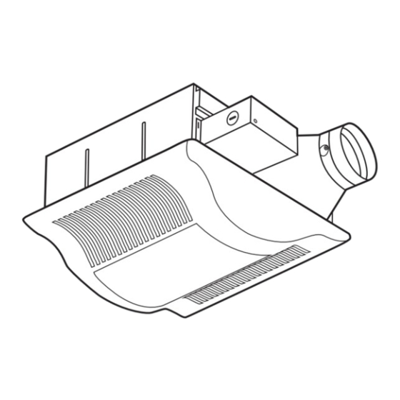
(ST4.2X12) DESCRIPTION The Panasonic ceiling mount ventilation fans uses a sirocco fan driven by a capacitor motor. The motor is designed to have an extended service life with reduced energy consumption. It also incorporates a thermal-cutoff for safety. The grille covering the main body is a spring-loaded, quick-release type. A damper for preventing counterflow is provided. -
Page 3: Dimensions
DIMENSIONS Unit: inches mm FV-08VSL1 1 25 6 5 / 1 6 ( 1 6 0 ) 2 7/8 73 2 3/8 60 1/2 13 1 1/2 38 3 1/8 78 3 6/8 95 13 330 10 1/4 261 3 3/4 (94) -
Page 4: Specifications
Lighting unit (sones) (inches) (rpm) (cfm) Fan body FV-08VSL1 18 X 2 12.8 (5 ) Specifications are based on HVI standard. UNPACKING Unpack and carefully remove unit from carton. Refer to the Supplied Accessories list to verify that all parts are present. -
Page 5: Wiring Diagram
GENE AL SAFETY INFO MATION CONTINUED GENE AL SAFETY INFO MATION CONTINUED (Cooking area) Do not install above or inside this area CAUTION: 1. For general ventilating use only. Do not use to exhaust hazardous or explosive materials and vapors. 2. -
Page 6: Installation I ( Joist Mounting- ) I
INSTALLATION INSTALLATION JOIST MOUNTING- JOIST MOUNTING- 1. Before installation, secure the fan body to adaptor by using thumb screw. (Fig.1) Thumb screw IMPORTANT : Remove the tape from damper and adaptor before installation. As shown below: Adaptor Fan body Damper Fig.1 Tape 2. - Page 7 INSTALLATION INSTALLATION JOIST MOUNTING- JOIST MOUNTING- ) CONTINUED ) CONTINUED 3. Install the suspension bracket and the flange of fan body to joists by using long screws (ST4.2X20) ( If spacing A between joists is 10 1/4~12 inches, install the flange of Joist fan body according to Fig.3-2, others according to Fig.3-1 install the product.)
- Page 8 INSTALLATION INSTALLATION JOIST MOUNTING- JOIST MOUNTING- ) CONTINUED ) CONTINUED 8. Finish ceiling work. Ceiling hole should be aligned with the edge of the flange. (Fig.6) Ceiling 9. Insert the plug connector and plug connector into the receptacle and receptacle respectively, and secure the light unit to the fan unit with 2 screw Plug connector II...
- Page 9 INSTALLATION INSTALLATION JOIST MOUNTING- JOIST MOUNTING- CONTINUED CONTINUED 4. Insert the suspension bracket in to fan body (refering Circular duct to step 2 of installation , page 6). Joist Conduit 5. Insert the fan body into joists. (Fig.9) IMPORTANT: Junction box cover Make sure that adaptor claws are properly inserted into body slots.
-
Page 10: Joist Mounting
INSTALLATION INSTALLATION III I ( - III I ( - JOIST MOUNTING JOIST MOUNTING 4 kind of joist inches (mm) 9/16 ( 14.3 11/16 (17.5) Fan body 31/32 (24.6) 1 17/32 38.9 Thumb screw Fig.13 Suspension bracket III Screw (ST4.2X12) Suspension bracket The suspension bracket... -
Page 11: Suspension Bracket
INSTALLATION INSTALLATION IV ( BETWEEN IV ( BETWEEN JOIST MOUNTING JOIST MOUNTING ) CONTINUED ) CONTINUED 3. Insert the fan body between joists. Joists Make sure the fan body is level and square (perpendicular) with the joists. (Fig.17) CAUTION: Backside of flange should mount directly to bottom of joist. Adaptor Fan body Junction box... -
Page 12: (St4.2X20)
INSTALLATION INSTALLATION WOODEN HEADE WOODEN HEADE R ) CONTINUED R ) CONTINUED 4. Follow step 5 to 11 of installation (page 7~page 8) to complete the installation work. Junction box Circular duct 6 Long screws (ST4.2X20) Conduit Junction box Wire nut Lead wires Green wires Fig.21... -
Page 13: Grille
MAINTENANCE MAINTENANCE CLEANING CLEANING Slot WARNING: Disconnect power source before working on unit. Routine maintenance must be done every year. Mounting spring CAUTION: 1. Never use petrol, benzene, thinner or any other such chemicals for cleaning the ventilating fan. Gloves 2. -
Page 14: Fluorescent
Receptacle II 4 W Night Lamp Fluorescent lamps Fig.26 3. Change the fluorescent lamps (Panasonic FDS 18E27/4,18 W or FDS18E35/4, 18 W or FDS18E42/4, 18 W ) or the 4 W night lamp, connect the connector or connector and replace the grille. (Fig.27) Fig.27... - Page 15 PANASONIC CONSUMER ELECTRONICS COMPANY Division of Panasonic Corporation of North America, One Panasonic Way, Secaucus, NJ 07094 PANASONIC CANADA INC. 5770 Ambler Driver, Mississauga, ON L4W 2T3 www.panasonic.com X0606-6048 08VSL1420F...
Need help?
Do you have a question about the FV-08VSL1 and is the answer not in the manual?
Questions and answers