Advertisement
Table of Contents
- 1 Table of Contents
- 2 Basic Specifications
- 3 Detailed Specifications
- 4 Controls
- 5 Connections
- 6 Operation
- 7 Exploded Views-Mechanical Parts List
- 8 Test Set-Up & Procedure
- 9 Block Diagram
- 10 Troubleshooting Flow Chart
- 11 Service Note - Power Transformer
- 12 Electrical Parts List
- 13 Pcb Drawings
- 14 IC - Transistor Pinouts
- 15 SCHEMATIC DIAGRAMS (120V)
- 16 Packaging
- Download this manual
See also:
Owner's Manual
Advertisement
Table of Contents

Summary of Contents for Infinity TSS-SUB4000
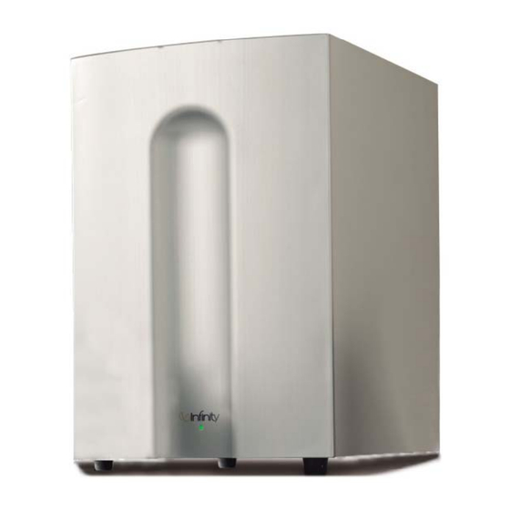
- Page 1 TSS-SUB4000 SERVICE MANUAL Infinity Systems Incorporated 250 Crossways Park Dr. Woodbury, New York 11797 Rev0 3/2005...
-
Page 2: Table Of Contents
(445mm x 438mm x 283mm) Weight 48 lb (21.8kg) Infinity continually strives to update and improve existing products, as well as create new ones. The specifications and construction details in this and related Infinity publications are therefore subject to change without notice. -
Page 3: Detailed Specifications
TSS-SUB4000 TSS-4000 subwoofer 300W Powered Sub/ Plate Amp LINE VOLTAGE Yes/No Hi/Lo Line Nom. Unit Notes US 120vac/60Hz 108-132 Vrms Normal Operation EU 230vac/50-60Hz 207-264 Vrms Normal operation, MOMS required Asia 100vac/50Hz 90-110 Vrms Normal Operation QA Test Parameter Specification... - Page 4 TSS-SUB4000 QA Test Parameter Specification Unit Conditions Notes Limits THD at Max. Output Power less than 10 % Maximum Output Power Maximum THD as a result of limiting. Output Volume Control Volume Control Pot mounted on amp panel Detent (center/#)
-
Page 5: Controls
TSS-SUB4000 ONTROLS AND ONNECTIONS Rear Panel ¡ ™ £ ¢ § ¶ ∞ • ª ¡ Subwoofer Level (Volume) Control Room Adaptive Bass Optimization System Controls (see page 5) § R.A.B.O.S. Selector ™ Line-Level Inputs ¶ R.A.B.O.S. Level Adjustment £ Normal/LFE Low-Pass Selector •... -
Page 6: Connections
TSS-SUB4000 ONNECTIONS If you have a Dolby* Digital or DTS ® receiver/processor If your receiver/processor has subwoofer with a low-frequency-effects (LFE) output: outputs for the left and right channels: • Set Low-Pass Switch to Off. • Set Low-Pass Switch to On. -
Page 7: Operation
TSS-SUB4000 PERATION Low-Pass Selector Power On Plug your subwoofer’s AC cord into a wall outlet. Do not use the If you have a Dolby Digital or DTS processor/receiver, the outlets on the back of the receiver. Crossover Frequency is set by the processor/receiver. Consult your owner’s manual to learn how to view or change this setting. -
Page 8: Exploded Views-Mechanical Parts List
TSS-SUB4000 TSS-SUB4000 EXPLODED VIEW Ref # Description Part Number Grille 329-120-05097-0VA Woofer/Trim Ring Screw 351-AM04030A893 Trim Ring 213-120-05033-0BA Woofer 12" (305mm) MMD 30PR14BW-DW01 Port Tube 249-HIPS-05021-0VA TSS-SUB4000 Amplifier Not for Sale Amplifier Screw 352-FM04020D605 TSS-SUB4000 Cabinet Not for Sale Rubber Foot... - Page 9 TSS-SUB4000 Ref # Description Part Number Screw 352-CM03530D926 Damping Main Mounting Bolt Tube Gasket Rubber 398-RUB-05093 Gasket Rubber Gasket 336-RUB-05013 Damping Power Transformer 150-R1107008 Damping...
-
Page 10: Test Set-Up & Procedure
TSS-SUB4000 TSS-SUB4000 Test Set Up and Procedure SYSTEM AURAL SWEEP TEST Equipment needed: • Function/signal generator/sweep generator • Multimeter • RCA cables General Unit Function (UUT = Unit Under Test) Switches/knobs on the amplifier faceplate: Phase switch – either position Low Pass switch –... -
Page 11: Block Diagram
TSS-SUB4000... -
Page 12: Troubleshooting Flow Chart
TSS-SUB4000 TSS-Sub4000 Testing Flow Chart Start Test protection Dc voltage check ±Vcc,±15V Check U ±15Vcc ect Check transformer 168, Test limiter circuit 124, Check U Power on check LED red &blue Check vol module Check THD output & connector power, noise cable&... -
Page 13: Service Note - Power Transformer
TSS-SUB4000 NOTICE The main power transformer (toroid) part# 150-r1107008 in the TSS-SUB4000 is not mounted in the amplifier inside the amp cover, but mounted in the cabinet in a separate location. Replacement: To replace the power transformer, it is necessary to remove the woofer from the cabinet. -
Page 14: Electrical Parts List
TSS-SUB4000 TSS-SUB4000 120V Electrical Parts List Part Number Description Reference Designator MAIN PCB Resistors 110-12621j15 Resistor 620Ω1/2W ± 5% 15mm R238 110-16102j26 Resistor 1K 1/6W ± 5% CF 26mm R210,R239,R264 110-16103j26 Resistor 10K 1/6W ± 5% CF 26mm R227,229,230,231,232,233,260,261,263 110-16153j26 Resistor 15K 1/6W ±... - Page 15 TSS-SUB4000 Part Number Description Reference Designator MAIN PCB Miscellaneous 109-1tsc103j0 thermister TSC05103J R237 162-10229004 wire assy 220mm AWG28 P107 171-udhss124d relay 5A 24V UDH-SS124D K101 175-1c02p01 coupling 2PIN PITCH=2.5mm P108 175-1c06v01 coupling 6PIN PITCH=2.5mm P105 175-1d02v01 coupling 2PIN PITCH=3.96mm P112...
- Page 16 TSS-SUB4000 Part Number Description Reference Designator INPUT/RABOS PCB Capacitors 129-a102j633 metalized Capacitor 0.001uF 63V ± 5% MSC C148 129-a103j633 metalized Capacitor 10NF 63V C183 129-a104j633 metalized Capacitor 0.1U 63V ± 5% MSC C116,137,138,139,143,118 129-a223j633 metalized Capacitor 0.022U 63V ± 5% MSC...
- Page 17 TSS-SUB4000 Part Number Description Reference Designator CLASS D AMP PCB 141-c7223k50 SMD Capacitor 0.022uF 50V 10% 1206 X7R 141-d7104ka0 SMD Capacitor 0.1uF 100V 10% 1210 X7R C12,C14,C18,C19 130-s1681kb03 disc Capacitor SL 680PF 200V 132-104kb50 mylar Capacitor 0.1U±10% 250V LS-10.mm MD 132-105kb50 mylar Capacitor 1uF 250V ±10%...
-
Page 18: Pcb Drawings
TSS-SUB4000... - Page 19 TSS-SUB4000...
- Page 20 TSS-SUB4000...
-
Page 21: Ic - Transistor Pinouts
TSS-SUB4000... -
Page 22: Schematic Diagrams (120V)
TSS-SUB4000... - Page 23 TSS-SUB4000...
- Page 24 TSS-SUB4000...
- Page 25 TSS-SUB4000...
- Page 26 TSS-SUB4000...
- Page 27 TSS-SUB4000...
- Page 28 TSS-SUB4000...
- Page 29 TSS-SUB4000...
- Page 30 TSS-SUB4000...
- Page 31 TSS-SUB4000...
-
Page 32: Packaging
TSS-SUB4000 PACKAGE Ref # Description Part Number Owner’s Manual 406-000-05133 Warranty Card 405-000-00328 Top/Bottom Packing 431-000-05293 Plastic Bag RABOS Kit 335852-003 Silica Gel Outer Carton 402-000-05237 15ft. RCA cable 166-015F011 TSS-SUB4000 TSS-SUB4000PLT...


Need help?
Do you have a question about the TSS-SUB4000 and is the answer not in the manual?
Questions and answers