Table of Contents
Advertisement
Advertisement
Table of Contents
Troubleshooting

Related Manuals for Furuno LS-6100


Summary of Contents for Furuno LS-6100
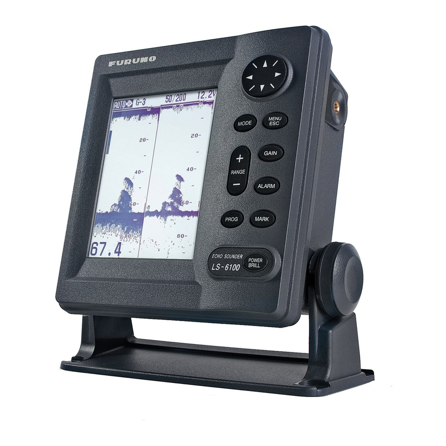
- Page 1 6" ECHO SOUNDER LS-6100...
- Page 2 All rights reserved. All rights reserved. Printed in Japan Printed in Japan PUB.No. PUB.No. OME-23690 OME-23690 ( ( DAMI DAMI ) ) LS-6100 LS-6100 Your Local Agent/Dealer Your Local Agent/Dealer FIRST EDITION : FIRST EDITION : FEB. FEB. 2002 2002 : JUN.
-
Page 3: Table Of Contents
TABLE OF CONTENTS FOREWORD ...iii SYSTEM OVERVIEW...iv 1. OPERATION ...1 1.1 Control Description ...1 1.2 Turning the Power On/Off ...1 1.3 Adjusting Display Contrast, Brilliance ...2 1.4 Choosing a Display, Frequency...2 1.5 Menu Operating Procedure ...5 1.6 Automatic Operation ...5 1.7 Manual Operation ...6 1.8 Choosing Picture Advance Speed...7... -
Page 4: Safety Instructions For The Operator
Immediately turn off the power at the switchboard if the equipment is emitting smoke or fire. Continued use of the equipment can cause fire or electrical shock. Contact a FURUNO agent for service. Do not maneuver the vessel based on the depth indication alone. -
Page 5: Safety Instructions For The Installer
The installer of the equipment is solely responsible for the proper installation of the equipment. FURUNO will assume no responsibility for any damage associated with improper installation. Use the specified power cable. -
Page 6: Foreword
Thank you for considering and purchasing FURUNO equipment. Features The FURUNO LS-6100 is a dual frequency (50 kHz, 200 kHz) monochrome LCD echo sounder. Comprised of a display unit and a transducer, the LS-6100 displays underwater conditions on a bright 6-inch monochrome LCD. -
Page 7: System Configuration
SYSTEM OVERVIEW System configuration Equipment lists Standard supply Name Display Unit LS-6100 520-5PSD Transducer 520-5MSD 520-5PWD 525ST-MSD Triducer (transducer plus spd/temp sensor) 525ST-PWD Tapping screw (4 pcs., 5 x 20 SUS304, 000-802-081) Installation Materials Washer head screw B (4 pcs., M4 x 20 SUS304, 000-804-742) (CP02-07000) Cable assy. -
Page 8: Operation
1. OPERATION 1.1 Control Description How to remove the hard cover Place your thumbs at the center of the cover, and then lift the cover while pressing it with your thumbs. Display unit 1.2 Turning the Power On/Off Press the [POWER/BRILL] key more than one second to turn on the power. -
Page 9: Adjusting Display Contrast, Brilliance
6" ECHO SOUNDER FURUNO ELECTRIC CO., LTD. ROM : OK RAM : OK Program No: 0252308-01.** ** Program version no. Start-up screen To turn off the power, press and hold down the [POWER/BRILL] key until the screen goes blank. -
Page 10: Dual Frequency Display
Single frequency display 50 kHz The sounder uses ultrasonic signals to detect bottom conditions. The lower the frequency of the signal, the wider the detection area. Therefore, the 50 kHz frequency is useful for general detection and judging bottom condition. 200 kHz The higher the frequency of the ultrasonic signal the better the resolution. -
Page 11: Nav Data Displays
Bottom-zoom display This mode expands bottom and bottom fish in the range width set with ZOOM RANGE on page 3 of the SYSTEM menu. This mode is useful for determining bottom contour. Single frequency display Bottom 29.8 Bottom-zoom display Bottom-zoom display Bottom-lock display The bottom-lock display provides a normal picture on the right half of the screen and a... -
Page 12: Menu Operating Procedure
1.5 Menu Operating Procedure The LS-6100 has three menus: Main menu (referred to in text as “menu”), System and Installation. Below is the basic menu operating procedure. 1. Press the [MENU/ESC] key to open the menu. Page 1 or Page 2 of the menu appears depending on the page last used. -
Page 13: Manual Operation
5. Press the [MENU/ESC] key to close the menu. The auto mode in use is shown as (Auto-Fishing) or (Auto-Cruising) at the top left corner on the screen. Range offset To display the bottom tail in detail in the automatic mode, offset the range as below. 1. -
Page 14: Adjusting The Gain
Table 1-1 Default ranges Basic Range Unit meters 10 20 feet 15 30 60 120 200 400 600 1000 fathoms 1. Press the [+] or [-] key of the [RANGE] key and the display should now look something like the one below. 2. -
Page 15: Measuring Depth
Fast Picture and picture advancement speed 1. Press the [MENU/ESC] key to open the menu. 2. Choose PIC. ADVANCE from page 1 of the menu. 3. Press ► to show the options window. Stop 1/16 Slow Fast Picture advance options window 4. -
Page 16: Suppressing Interference
1. Press the [MENU/ESC] key to open the menu. 2. Press ▲ or ▼ to choose A-SCOPE from page 1 of the menu. 3. Press ► to show the options window. 4. Press ▲ or ▼ to choose the A-scope presentation type desired. -
Page 17: Erasing Weak Echoes
1.13 Erasing Weak Echoes Sediment in the water or reflections from plankton may be painted on the display in low intensity tones. Appearance of weak echoes These weak echoes may be erased as follows: 1. Press the [MENU/ESC] key to open the menu. -
Page 18: Setting Destination Waypoint
2. Use ▲ or ▼ to set the cursor where desired. Picture advancement is stopped until step 3 is completed. 3. Press the [MARK] key again. The latitude and longitude position at the cursor is output to the navigator and a vertical line marks location. -
Page 19: Prog Key
2. Use ▲ or ▼ to choose GOTO WPT from page 2 of the menu. 3. Press ► to open the waypoints list. -------- -------- -------- -------- -------- -------- -------- -------- Waypoint list 4. Use ▲ or ▼ to choose a waypoint. 5. -
Page 20: Picture Color (Hue)
5. Press the [MENU/ESC] key to close the menu. 1.19 Alarms Alarm description The LS-6100 has six conditions which generate both audio and visual alarms: bottom alarm, normal fish alarm, bottom lock fish alarm, water temperature alarm, arrival alarm and speed alarm. (The water temperature, arrival and speed alarms require appropriate sensors.) - Page 21 ALARM BOTTOM FROM : RANGE : 10ft FISH(Normal) : On FROM : RANGE : 10ft FISH(B/L) : On FROM : RANGE : 1.0ft FISH LEVEL : Medium [MENU]: Exit ALARM TEMPERATURE Inside FROM : 72.4 F RANGE : 1.0 F SPEED : Off FROM :...
-
Page 22: Resetting Trip Distance
Alarm range Alarm range marker Bottom alarm, Fish alarm (normal): Right Fish alarm (bottom/lock): Left * Alarm icon : Bottom alarm : Fish alarm (normal) : Fish alarm (B/L) : Temperature alarm ( C or F shown) : Speed alarm : Arrival alarm How the alarm works Note: To disable an alarm, choose Off at... -
Page 23: Setting Up Nav Data Displays
1.23 Setting Up Nav Data Displays The user may arrange the nav data displays as desired. 1. Use the [MODE] key to select the nav data display you want to set up. 2. Press the Cursor Pad to display the NAV DATA SETUP window. - Page 24 GRAPHIC DISPLAYS 0.25 XTE GRAPHIC Speed 17.2 SPEED GRAPHIC Wind APP* 10.3 Speed WIND GRAPHIC Wpt 03 Destination Rng 0.19nm Brg 321 XTE 0.00nm Cse 333 waypoint data: Name, Range, DESTINATION WAYPOINT GRAPHIC Bearing to destination waypoint COMPASS GRAPHIC Depth 32.8 DEPTH XTE scale...
-
Page 25: System & Installation Menus
2. SYSTEM & INSTALLATION MENUS The System menu mainly consists of items which once set do not require frequent adjustment. You may display this menu by choosing SYSTEM MENU at page 2 of the menu and pressing ►. SYSTEM MENU PAGE 1 LANGUAGE English... - Page 26 TLL (Target Latitude, Longitude) position when the [MARK] key is operated. “TLL” outputs latitude and longitude position. “FURUNO-TLL,” available with connection of navigator that can output FURUNO TLL, outputs latitude and longitude, water temperature, depth, etc. BEARING: Ship’s course and bearing to a waypoint may be displayed in true or magnetic bearing.
-
Page 27: Installation Menu
Page 3 BASIC RANGE 1 - BASIC RANGE 8: Set range of each of the eight basic ranges. Note 1: All default basic ranges are restored whenever the depth unit is changed. Therefore, change the depth unit before changing the basic ranges. Note 2: A range may not be lower than the range preceding it. - Page 28 TEST: Conducts diagnostic tests. For further details, see paragraph 3.7. LCD PATTERN: Tests the LCD. For further details, see paragraph 3.8 MEMORY CLEAR: The memory can be cleared to start afresh with default menu settings. 1. At the installation menu, press ▼ to choose MEMORY CLEAR.
-
Page 29: Maintenance, Troubleshooting
3. MAINTENANCE, TROUBLESHOOTING WARNING ELECTRICAL SHOCK HAZARD Do not open the equipment. Only qualified personnel should work inside the equipment. 3.1 Maintenance Regular maintenance is essential for good performance. Checking the items listed in the table below monthly will help keep your equipment in good shape for years to come. -
Page 30: Troubleshooting
3.6 Troubleshooting The table below provides basic troubleshooting procedures which the user may follow to restore normal operation. Troubleshooting table If… Then check … neither echo nor battery voltage. fixed range scale fuse. appears power supply. power cable. no echo appears if display advance but the fixed speed is set to “Stop.”... -
Page 31: Test Pattern
4. The ROM, RAM and NMEA port are checked, with the results shown as OK or NG (No Good). For any NG, request service. (A special connector is required to test the NMEA port. Nothing appears if no connector is connected.) 5. -
Page 32: Installation
4. INSTALLATION 4.1 Display Unit Mounting considerations The display unit can be installed on a desktop, on the overhead or flush mounted in a panel. When choosing a mounting location keep the following in mind: Keep the display unit out of direct sunlight. - Page 33 A practical choice would be somewhere between 1/3 and 1/2 of the boat’s length from the stern. For planing hulls, a practical location is generally rather far astern, so that the transducer is always in water regardless of the planing attitude. 520-5PSD 520-5MSD Thru-hull mount transducer mounting...
-
Page 34: Transom Mount Transducer
Hole for stuffing tube Upper Half Lower Half Saw along slope of hull. Construction of fairing block 3. Drill a hole just large enough to pass the threaded stuffing tube of the transducer through the hull, making sure it is drilled vertically. -
Page 35: Transducer Preparation
5 x 20 No.1 ° Tape Transom mount transducer, mounting flush with hull Installing the transom mount transducer on a deep-V hull This method is employed on deep-V hulls and provides good performance because the effects of air bubbles are minimal. Install the transducer parallel with water surface;... -
Page 36: Inside-Hull Transducer
4.4 Inside-hull Transducer The thru-hull mount transducer (520-5PSD, 520-5MSD) may also be installed inside the hull, following the procedure below. Necessary tools You will need the following tools: Sandpaper (#100) Silicone sealant Silicone grease Remarks on installation Turn off the engine and anchor the boat while installing the equipment. -
Page 37: Final Preparation
10. If the bottom is displayed in dark gray and the depth indication appears, the mounting location is suitable. Go to “Final preparation.” 11. If the bottom is not displayed in dark gray tone, the mounting location may be unsuitable. Do the following: a) Press the [POWER/BRILL] key to turn off the power. - Page 38 Height without speed sensor 191mm (7-1/2") Height with speed sensor 213mm (8-1/2") Height required at mounting location Note 1: Do not mount the sensor in an area of turbulence or bubbles: near water intake or discharge openings; behind strakes, struts, fittings, or hull irregularities; behind eroding paint (an indication of turbulence).
- Page 39 If you do not know the transom angle, temporarily attach the bracket and sensor to the transom to determine if the plastic shim is needed. 5. Using the two #10 x 1-1/4” self-tapping screws, temporarily screw the bracket to the hull. DO NOT tighten the screws completely at this time.
- Page 40 Attaching the sensor to the bracket 1. If the retaining cover near the top of the bracket is closed, open it by depressing the latch and rotating the cover downward. Step 1 Step 2 Latch Pivot arm (2) Retaining cover Step 3 Step 4 Attaching the sensor to the bracket...
-
Page 41: Optional Water Temperature/Speed Sensor
4.6 Optional Water Temperature/Speed Sensor Water temperature/speed sensor ST-02MSB and ST-02PSB, which are designed for thru-hull mounting, are optionally available. Install them as shown below. Mounting considerations Choose a suitable mounting location considering the following: Choose a place free from vibration. Choose a mid-boat flat position. -
Page 42: Optional Equipment
IEC-61162-1/NMEA0183 RD-B +Vout Power output max. 100 mA* * = The LS-6100 can feed 12 V power to GP-310B, GP-320B. The power voltage must be at least 12 V to feed power to those units. NMEA port setup The NMEA port can function as an input port or input/output port. -
Page 43: Iec 61162-1 Data Sentences
Wind sensor DISPLAY UNIT ¬ Wind Sensor 12 VDC NMEA port setting: IN/OUT Connection of wind sensor Feeding data to RD-30 via the LS-6100 GP-310B DISPLAY UNIT* ® RD-30 12/24 VDC Wind Sensor 12 VDC NMEA port setting: IN/OUT NMEA mix setting: ON *: Navigator-related data not displayed. -
Page 44: Specifications
SPECIFICATIONS OF THE ECHO SOUNDER LS-6100 1. GENERAL 1.1 TX Frequency 50 kHz or 200 kHz, 50/200 kHz dual transmitting selectable 1.2 Transmit Method Single or dual transmitting 1.3 Output Power 300 Wrms 1.4 TX Rate Max. 550 pulse/min 1.5 Pulse-length 0.1 to 1.0 ms...
Need help?
Do you have a question about the LS-6100 and is the answer not in the manual?
Questions and answers