Table of Contents
Advertisement
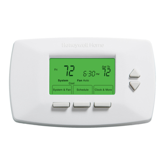
Programmable Thermostat
The RTH7400D Thermostat provides electronic control of 24 Vac
heating and cooling systems or 750 mV heating systems.
For assistance with your Honeywell product, please visit
www.honeywell.com/yourhome or call Honeywell Customer Care
toll free at 1-800-468-1502.
Read and Save these Instructions
Patents Pending
® U.S. Registered Trademark
© 2004 Honeywell International Inc.
All Rights Reserved
RTH7400D
OWNER'S GUIDE
69-1726-1
Advertisement
Table of Contents

Related Manuals for Honeywell RTH7400D


Summary of Contents for Honeywell RTH7400D
-
Page 1: Programmable Thermostat
RTH7400D Programmable Thermostat OWNER’S GUIDE The RTH7400D Thermostat provides electronic control of 24 Vac heating and cooling systems or 750 mV heating systems. For assistance with your Honeywell product, please visit www.honeywell.com/yourhome or call Honeywell Customer Care toll free at 1-800-468-1502. -
Page 2: Table Of Contents
Contents Prepare for Installation ............3 Follow Important Instructions ..........5 Remove Old Thermostat ............6 Follow Special Instructions............7 Label Old Thermostat Wires ........... 10 Mount New Wallplate to Wall ..........11 Connect Wires to New Wallplate..........15 Install Batteries................ 23 Attach New Thermostat to Wallplate ........ -
Page 3: Prepare For Installation
ÓN fusibles-interruptor té V/VR V/VR Read and save these instructions ell.com/yourhome M22278 If any of the items shown above are missing, call Honeywell Customer Care at 1-800-468-1502 before returning the thermostat to the store. 69-1726—1... - Page 4 Step 1. Prepare for Installation (Cont) 2. Check that you have everything required for the installation: • Two AA alkaline batteries • No. 2 Phillips screwdriver and standard pocket screwdriver • Drill • Drill bit—use 3/16 in. for drywall; use 7/32 in. for plaster •...
-
Page 5: Follow Important Instructions
Step 2. Follow Important Instructions 1. Do not connect the wires to the new thermostat based on wire color because damage can occur to the heating and/or cooling system. These Installation Instructions explain later how to use the enclosed wire labels to correctly mark the wires connected to your old thermostat. -
Page 6: Remove Old Thermostat
Step 3. Remove Old Thermostat 1. Turn off power at the heating and/or cooling system or fuse/circuit breaker panel. 2. Remove the cover from the old thermostat. 3. Remove the old thermostat from the wall or wall- plate. Do not remove the wires. OLD THERMOSTAT WALLPLATE THERMOSTAT... -
Page 7: Follow Special Instructions
Step 4. Follow Special Instructions 1. If you have two C and/or C1 wires connected to your old thermostat, do not connect them to your new thermostat. 2. Disconnect the C and/or C1 wires. Make sure they do not touch each other or any other wires. 3. - Page 8 Step 4. Follow Special Instructions (Cont) 4. If you have only one C and/or C1 wire connected to your old thermostat, connect this wire to C on the new thermostat. OLD THERMOSTAT LETTER DESIGNATION SCREW TERMINAL WIRE WIRE HOLE CONNECT TO THE "C" ON THE NEW THERMOSTAT M22223 69-1726—1...
- Page 9 Step 4. Follow Special Instructions (Cont) 5. If you find any wires not connected to your old thermostat, do not connect them to your new thermostat. 6. Wrap the end of the wires that are not connected with electrical tape. OLD THERMOSTAT LETTER DESIGNATION SCREW TERMINAL...
-
Page 10: Label Old Thermostat Wires
Step 5. Label Old Thermostat Wires 1. As you disconnect each wire, use the enclosed wire labels to wrap a wire label around each wire that matches the letter designation. Do not allow the wires to fall into the wall opening after the wires are disconnected. -
Page 11: Mount New Wallplate To Wall
Step 6. Mount New Wallplate to Wall 1. Separate the wallplate from the thermostat as shown. WALLPLATE WIRE HOLE THERMOSTAT M22267 69-1726—1... - Page 12 Step 6. Mount New Wallplate to Wall (Cont) 2. Pass the labeled wires through the wire hole on the wallplate. WALL OPENING WIRE HOLE LABELED WIRES M22279 69-1726—1...
- Page 13 Step 6. Mount New Wallplate to Wall (Cont) 3. Position the wallplate on the wall with the arrow pointing up. Level the wallplate (for appearance only) and mark the two mounting holes with a pencil. PLACE LEVEL ON SUPPORT TABS LEVEL MARK MOUNTING...
- Page 14 Step 6. Mount New Wallplate to Wall (Cont) 4. Move the wallplate aside and drill holes at the locations marked on the wall. Drill 3/16 in. holes for drywall or 7/32 in. holes for plaster. 5. Tap the wall anchors into the drilled holes until even with the wall surface.
-
Page 15: Connect Wires To New Wallplate
Step 7. Connect Wires to New Wallplate 1. Match the labeled wires to the letter designations on the wallplate. 2. Select the correct letter designations to follow for your system. If you have a standard heating and/or cooling system, use the CONVENTIONAL letter designations. - Page 16 Step 7. Connect Wires to New Wallplate (Cont) 3. If wires are to be connected to both Rc and R, loosen the Rc and R screw terminals and remove the metal jumper wire. 4. If only one of the terminals, Rc or R, is to be connected, leave the metal jumper wire in place.
- Page 17 Step 7. Connect Wires to New Wallplate (Cont) 5. Loosen the screw terminals. Insert the labeled wires into the holes on the side of the terminal block that match the letter designations. Tighten the screw terminals. 6. If any of the labeled wires do not match the letter designations, see next page for wire connections.
- Page 18 Step 7. Connect Wires to New Wallplate (Cont) 7. Compare letter designations on your old and new thermostats. Use the information below if you are wiring a CONVENTIONAL System. Use the information on page 20 if you are wiring a Heat Pump system.
- Page 19 Step 7. Connect Wires to New Wallplate (Cont) NOTES FOR CONVENTIONAL HEATING AND COOLING SYSTEMS If wires will be connected to both R and R on the new thermostat, remove metal jumper wire between R and R. Leave metal jumper wire in place if only one of the terminals, R or R, will be connected on the new thermostat.
- Page 20 Step 7. Connect Wires to New Wallplate (Cont) 8. Compare letter designations on your old and new thermostats. Use the information below if you are wiring a HEAT PUMP system. Possible letter HEAT PUMP letter designations on designations on the the labeled wires new thermostat VR or V or...
- Page 21 B wire to the C letter designation on the new thermostat. If another wire is already matched to the C, contact Honeywell. If the old thermostat had wires on W1, Y1 and W2, some system modification is required. Call your local heating and cooling contractor for assistance.
- Page 22 Step 7. Connect Wires to New Wallplate (Cont) 9. Push excess wire back into the wall opening. Keep wires in the shaded area. WIRE WALLPLATE WALL OPENING SHADED AREA M22297 69-1726—1...
-
Page 23: Install Batteries
Step 8. Install Batteries 1. Install two fresh AA alkaline batteries on the back of the thermostat as marked on the thermostat. BATTERIES (2) BATTERY HOLDER M22259 BACK OF THERMOSTAT 2. Remove tab labeled “Remove during installation” in the lower right corner of the thermostat back. REMOVE M22298 69-1726—1... -
Page 24: Attach New Thermostat To Wallplate
Step 9. Attach New Thermostat to Wallplate 1. Align the screw blocks with the pins on the back of the thermostat. WALLPLATE TERMINAL SCREW BLOCK PINS ON BACK OF THERMOSTAT M22299 2. Push the thermostat straight onto the wallplate until it snaps into place. -
Page 25: Set Calendar
Step 10. Set the Calendar This thermostat is designed to automatically keep current time and day in memory for up to ten years, under normal use, once the calendar is set. When the thermostat is first powered, the display is ready to set the calendar. 1. - Page 26 Step 10. Set the Calendar (Cont) 6. Press the Done button to advance to the Time. 7. Use the Up or Down arrow button to set the Time. UP AND DOWN BUTTONS CHANGES TIME Clock More Done DONE BUTTON ADVANCES TO HOME SCREEN M22303 8.
-
Page 27: Configure Installer Setup
Step 11. Configure Installer Setup 1. Use the Installer Setup Menu to match your new thermostat to your heating and/or cooling system. Follow the steps in this section to set up your thermostat. 2. Press and release the System button. Set To System Auto... - Page 28 Step 11. Configure Installer Setup (Cont) 3. Press and hold the center button for approximately five seconds, until the screen changes. System Auto Fan Auto Heat Off Cool FanUseEdit System & Fan CancelDone M22305 4. Release the center button when the display on your thermostat matches the display below.
- Page 29 11. Configure Installer Setup (Cont) 5. Press the Up or Down arrows to select your setting for Installer Setup Number 0120 below. 6. After you select your setting, press the Next button to go to the next Installer Setup Number. 7.
- Page 30 Step 11. Configure Installer Setup (Cont) 8. Press the Up or Down arrows to select your setting for Installer Setup Number 0170. 9. After you select your setting, press the Next button to go to the next Installer Setup Number. SETTING INSTALLER Set To...
- Page 31 Step 11. Configure Installer Setup (Cont) 10. If you do not have a number 0180 on the left side of your display, go to the next page. 11. If you have a number 0180 on the left side of your display, press the Up or Down arrow to select your setting for Installer Setup Number 0180.
- Page 32 Step 11. Configure Installer Setup (Cont) 13. If you do not have a number 0190 on the left side of your display, go to the next page. 14. If you have a number 0190 on the left side of your display, press the Up or Down arrow to select your setting for Installer Setup Number 0190.
- Page 33 Step 11. Configure Installer Setup (Cont) 16. If you do not have a number 0240 on the left side of your display, go to the next page. 17. If you have a number 0240 on the left side of your display, press the Up or Down arrow to select your setting for Installer Setup Number 0240.
- Page 34 Step 11. Configure Installer Setup (Cont) 19. Press the Up or Down arrow to select your setting for Installer Setup Number 0320. 20. After you select your setting, press the Next button to go to the next Installer Setup Number. SETTING Period Wake Leave...
- Page 35 Step 11. Configure Installer Setup (Cont) 21. Press the Up or Down arrow to select your setting for Installer Setup Number 0330. 22. After you select your setting, press the Next button to go to the next Installer Setup Number. SETTING Period Wake Leave...
- Page 36 Step 11. Configure Installer Setup (Cont) 23. Press the Up or Down arrow to select your setting for Installer Setup Number 0500. 24. After you select your setting, press the Next button to go to the next Installer Setup Number. SETTING Period Wake Leave...
- Page 37 Step 11. Configure Installer Setup (Cont) 25. Press the Up or Down arrow to select your setting for Installer Setup Number 0530. 26. After you select your setting, press the Next button to go to the next Installer Setup Number. SETTING Period Wake Leave...
- Page 38 Step 11. Configure Installer Setup (Cont) 27. Press the Up or Down arrow to select your setting for Installer Setup Number 0640. 28. After you select your setting, press the Done key to exit the Installer Setup and save your settings. 29.
-
Page 39: Controls & Features
Get to Know Your Thermostat Buttons Thermostat DOWN BUTTON LOWERS TEMPERATURE SETTING OR MAKES SELECTIONS IN OTHER SCREENS UP ARROW BUTTON RAISES TEMPERATURE SETTING OR MAKES SELECTIONS IN OTHER SCREENS System System & Fan Schedule Clock & More SCHEDULE BUTTON SELECTS PROGRAMMING MODE CLOCK &... - Page 40 Get to Know Your Thermostat Display Display TEMPERATURE SHOWS CURRENT SETTING DAY OF WEEK CURRENT TIME System Schedule Clock & More CURRENT INDICATES THERMOSTAT IS SYSTEM SETTING "CALLING FOR COOL OR HEAT" CURRENT FAN SETTING M22317 69-1726—1...
- Page 41 Set System Setting Set System Setting Press the System button to select Heat, Off or Cool: Heat—Thermostat controls the heating system. Off—Heating and cooling systems are both off. Cool—Thermostat controls the cooling system. Em. Heat (Heat Pump Systems with Auxiliary Heat)—Thermostat controls emergency heat and auxiliary heat, if needed.
- Page 42 Set System Setting (Cont) Set Fan Setting 1. Press System & Fan button. 2. Press the Fan button to select Auto or On: Auto—Normal setting for most homes.The fan runs only when the heating or cooling system is on. On—The fan runs continuously. Use this setting for improved air circulation or for more efficient air cleaning.
- Page 43 Program Your Heating and Cooling Schedule Your thermostat can control up to four different schedule periods Monday through Friday and Saturday and/or Sunday : Wake—Period when you awaken and want your home at a comfortable temperature. Leave—Period when you are away from home and want an energy-saving temperature.
- Page 44 Program Your Heating and Cooling Schedule (Cont) 2. Press the Edit button. Edit View Go Back M22331 69-1726—1...
- Page 45 Program Your Heating and Cooling Schedule (Cont) 3. Monday through Friday flashes. Press the Select Day button to select Monday through Friday. The days selected are scheduled with the same times and temperatures. Checkmarks appear next to the days selected. Select Day Next Step...
- Page 46 Program Your Heating and Cooling Schedule (Cont) 4. Press the Next Step button. Once pressed, Wake flashes to show it is selected. DAYS SCHEDULE HEAT OR COOL SELECTED PERIOD TEMPERATURES UP ARROW CHANGES TIME Period Wake Leave TEMPERATURES Go Back Next Step Done DOWN ARROW...
- Page 47 Program Your Heating and Cooling Schedule (Cont) 12. When complete, press the Done button. “Saved” appears on the display to indicate changes are being saved to the day(s) selected. Saved M22334 13. To set a program schedule for Saturday and Sunday, repeat steps 1 through 12.
- Page 48 Set Time Set Time 1. Press Clock & More button. 2. Use the Up and Down arrow buttons to set the current time. Go Back Done M22335 3. Press the Done button. The current day of the week should already be set correctly.
- Page 49 Set Temperature Overrides Hold Temperature Until (Temporary Hold) Hold temperature temporarily until the next scheduled period time. 1. Press the Up or Down arrow buttons next to the temperature you want to adjust. “Temporary” appears on the display above the set temperature. MOVES TEMPERATURE SETTING UP OR DOWN M22336...
- Page 50 Set Temperature Overrides (Cont) Permanent Hold Permanent Hold changes the temperature setting until Permanent Hold is cancelled. 1. Use the Up or Down arrow buttons to set the temperature you want during the hold. 2. Press the Hold button. “Permanent Hold” shows on the display.
- Page 51 Use Your Filter Timer The Filter Timer notifies you when to change your furnace filter. Reset Filter Timer 1. “Change Filter” appears on the display when the filter timer expires. 2. Press the Reset button to restart the filter timer. System Heat Schedule...
- Page 52 Use Your Filter Timer (Cont) View or Reset The Remaining Change Filter Time 1. Press the Clock & More button. 2. Press the Next button. Change Filter Days Reset Next Done M22339 3. Press the Reset button to Restart the filter timer, if desired.
- Page 53 Understand Temperature Recovery Feature Your thermostat comes with a feature called Adaptive Intelligent Recovery™, which eliminates all guesswork when setting your schedule. How long does it take the furnace to warm your house in the morning before you get out of bed or how long does it take the air conditioner to cool your house in the afternoon before you return from work? No problem.
- Page 54 Replace Batteries 1. When the LO Battery indicator is flashing, replace the batteries promptly with two fresh AA alkaline batteries. M22322 2. Remove thermostat from the wallplate by pulling straight out. M22323 69-1726—1...
- Page 55 Replace Batteries (Cont) 3. Remove the old batteries and insert two fresh AA alkaline batteries, as marked on the thermostat. BATTERIES (2) BATTERY HOLDER M22259 BACK OF THERMOSTAT 69-1726—1...
- Page 56 Replace Batteries (Cont) 4. Align the screw blocks with the pins on the back of the thermostat. WALLPLATE TERMINAL SCREW BLOCK PINS ON BACK OF THERMOSTAT M22299 5. Push the thermostat straight onto the wallplate until it snaps into place. 69-1726—1...
- Page 57 Review Battery Tips 1. Replace the batteries as soon as LO Batt flashes in the display. The LO Battery indicator flashes in the display one month before the batteries run down completely. 2. Always use fresh AA alkaline batteries. Non-alka- line batteries do not last as long and can leak, causing thermostat damage.
- Page 58 Built-in Compressor Protection The RTH7400D Thermostat has built-in compressor protection (minimum-off timer) that prevents the compressor from restarting too early after a shutdown. The minimum-off timer is activated after the compressor turns off. If there is a call during the minimum-off timer, the thermostat shows “Wait”...
- Page 59 Troubleshooting Tips If . . . Then . . . Display is Check that fresh AA alkaline batteries are blank. installed as marked on the thermostat. Temperature Check that the temperature settings are: settings do not • Heating 40°F to 90°F(4.5°C to 32°C). change.
- Page 60 Troubleshooting Tips (Continued) If . . . Then . . . Cannot set Check Installer Setup Number 0170, System setting Heating and/or Cooling System Type; make to Cool. sure the setting matches the installed heating and/or cooling system. “Heat On” is Set the System setting to Heat and set the not shown in temperature setting above the room...
- Page 61 Troubleshooting Tips (Continued) If . . . Then . . . Both the Check Installer Setup Number 0170, heating and Heating and/or Cooling System Type, and cooling make sure the setting matches the installed systems are heating and/or cooling system. running at the Check and make sure the bare portions of same time.
-
Page 62: Customer Assistance
Customer Assistance For assistance with your Honeywell product, please visit www.honeywell.com/yourhome or call Honeywell Customer Care toll free at 1-800-468-1502. 69-1726—1... -
Page 63: Limited One-Year Warranty
Golden Valley, MN 55422 This warranty does not cover removal or reinstallation costs. This warranty shall not apply if it is shown by Honeywell that the defect or malfunction was caused by damage which occurred while the product was in the possession of a consumer. - Page 64 If you have any questions concerning this warranty, please write Honeywell Customer Relations, 1985 Douglas Dr, Golden Valley, MN 55422 or call 1-800-468-1502. In Canada, write Retail Products ON15-02H, Honeywell Limited/Honeywell Limitée, 35 Dynamic Drive, Scarborough, Ontario M1V4Z9.
Need help?
Do you have a question about the RTH7400D and is the answer not in the manual?
Questions and answers