Toshiba Qosmio X300 Series User Manual
Hide thumbs
Also See for Qosmio X300 Series:
- Maintenance manual (255 pages) ,
- User manual (232 pages) ,
- Resource manual (56 pages)
Table of Contents
Advertisement
Quick Links
Advertisement
Chapters
Table of Contents

Related Manuals for Toshiba Qosmio X300 Series


Summary of Contents for Toshiba Qosmio X300 Series
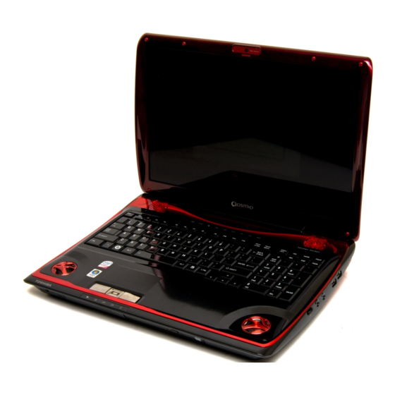
- Page 1 User’s Manual Qosmio X300 Series...
-
Page 2: Table Of Contents
Special features ......... 1-11 TOSHIBA Value Added Package ......1-13... - Page 3 Writng CD/DVD on DVD Super Multi drives ....4-18 TOSHIBA DVD PLAYER ........4-28 Remote Controller .
- Page 4 TOSHIBA support ........
- Page 5 Regulatory statements ........D-2 Using Bluetooth™ Card from TOSHIBA equipment in Japan ..D-4...
-
Page 6: Copyright
This manual has been validated and reviewed for accuracy. The instructions and descriptions it contains are accurate for the TOSHIBA Qosmio X300 Portable Personal Computer at the time of this manual’s production. However, succeeding computers and manuals are subject to change without notice. -
Page 7: Trademarks
PalmCheck and TouchPad are trademarks of Synaptics Incorporated. ExpressCard is a trademark of PCMCIA. ConfigFree is a trademark of Toshiba Corporation. Wi-Fi is a registered trademark of the Wi-Fi Alliance. Secure Digital and SD are trademarks of SD Card Association. -
Page 8: Fcc Information
Only peripherals complying with the FCC class B limits may be attached to this equipment. Operation with non-compliant peripherals or peripherals not recommended by TOSHIBA is likely to result in interference to radio and TV reception. Shielded cables must be used between the external devices and the computer’s external monitor port, Universal Serial Bus... -
Page 9: Eu Declaration Of Conformity
"CE" and comply therefore with the applicable harmonized European standards listed under the Low Voltage Directive 2006/95/EC, the EMC Directive 2004/108/EC and/or R&TTE Directive 1999/5/EC. Responsible for CE- TOSHIBA EUROPE GMBH, Hammfelddamm 8, marking: 41460 Neuss, Germany. manufacturer: Toshiba Corporation, 1-1 Shibaura 1-chome,... -
Page 10: Modem Warning Notice
Qosmio X300 Modem warning notice This information is applicable to the models equipped with a built-in modem. Conformity Statement The equipment has been approved to [Commission Decision “CTR21”] for pan-European single terminal connection to the Public Switched Telephone Network (PSTN). - Page 11 Qosmio X300 Redial Up to two redial attempts can be made. If more than two redial attempts are made, the modem will return Black Listed. If you are experiencing problems with the Black Listed code, set the interval between redials at one minute or longer.
-
Page 12: Type Of Service
FCC. In the event repairs are ever needed on your modem, they should be performed by TOSHIBA Corporation or an authorized representative of TOSHIBA Corporation. -
Page 13: Instructions For Ic Cs-03 Certified Equipment
Qosmio X300 Fax branding The Telephone Consumer Protection Act of 1991 makes it unlawful for any person to use a computer or other electronic device to send any message via a telephone fax machine unless such a message clearly contains in a... -
Page 14: Notes For Users In Australia And New Zealand
Qosmio X300 The Ringer Equivalence Number (REN) assigned to each terminal device provides an indication of the maximum number of terminals allowed to be connected to a telephone interface. The termination on an interface may consist of any combination of devices subject only to the requirement that the sum of the Ringer Equivalence Numbers of all the devices does not exceed 5. - Page 15 Qosmio X300 Notes for use of this device in New Zealand ■ The grant of a Telepermit for a device in no way indicates Telecom acceptance of responsibility for the correct operation of that device under all operating conditions. In particular the higher speeds at which...
-
Page 16: General Conditions
Qosmio X300 ■ When used in Auto Answer mode, the S0 register must be set with to a value of either 3 or 4. This ensures: ■ a person calling your modem will hear a short burst of ringing before the modem answers. -
Page 17: Optical Disc Drive Safety Instructions
Qosmio X300 The Telepermit label may also be shown on the packaging of the product and in the sales literature, as required in PTC 100. The charge for a Telepermit assessment is $337.50. An additional charge of $337.50 is payable where an assessment is based on reports against non-Telecom New Zealand Specifications. - Page 18 Qosmio X300 Panasonic DVD Super Multi drive UJ870 ■ The DVD Super Multi drive employs a laser system. To ensure proper use of this product, please read this instruction manual carefully and retain for future reference. Should the unit ever require maintenance, contact an authorized service location.
- Page 19 Qosmio X300 Pioneer DVD Super Multi drive DVR-TD08TBA/ DVR-TD08TBC ■ The DVD Super Multi drive employs a laser system. To ensure proper use of this product, please read this instruction manual carefully and retain for future reference. Should the unit ever require maintenance, contact an authorized service location.
- Page 20 Qosmio X300 Hitach-LG Data Storage DVD Super Multi drive GSA-T50N/ GSA-T50F ■ The DVD Super Multi drive employs a laser system. To ensure proper use of this product, please read this instruction manual carefully and retain for future reference. Should the unit ever require maintenance, contact an authorized service location.
-
Page 21: International Precautions
Qosmio X300 International precautions CAUTION: This appliance contains a laser system and is classified as a “CLASS 1 LASER PRODUCT.” To use this model properly, read the instruction manual carefully and keep this manual for your future reference. In case of any trouble with this model, please contact your nearest “AUTHORIZED service... - Page 22 Qosmio X300 VAROITUS. Suojakoteloa si saa avata. Laite sisältää laserdiodin, joka lähetää näkymätöntä silmilie vaarallista lasersäteilyä. CAUTION: USE OF CONTROLS OR ADJUSTMENTS OR PERFORMANCE OF PROCEDURES OTHER THAN THOSE SPECIFIED IN THE OWNER’S MANUAL MAY RESULT IN HAZARDOUS RADIATION EXPOSURE.
-
Page 23: Preface
Windows is running, you can display or record a TV program using the My TV feature of Media Center. This manual tells how to set up and begin using your Qosmio X300 computer. It also provides detailed information on configuring your computer, basic operations and care, using optional devices and troubleshooting. - Page 24 Qosmio X300 Abbreviations On first appearance, and whenever necessary for clarity, abbreviations are enclosed in parentheses following their definition. For example: Read Only Memory (ROM). Acronyms are also defined in the Glossary. Icons Icons identify ports, dials, and other parts of your computer. The indicator...
- Page 25 Qosmio X300 Indicates a potentially hazardous situation, which could result in death or serious injury, if you do not follow instructions. Terminology This term is defined in this document as follows: Start The word "Start" refers to the " " button in ®...
-
Page 26: General Precautions
General Precautions TOSHIBA computers are designed to optimize safety, minimize strain and withstand the rigors of portability. However, certain precautions should be observed to further reduce the risk of personal injury or damage to the computer. Be certain to read the general precautions below and to note the cautions included in the text of the manual. -
Page 27: Creating A Computer-Friendly Environment
Qosmio X300 Creating a computer-friendly environment Place the computer on a flat surface that is large enough for the computer and any other items you are using, such as a printer. Leave enough space around the computer and other equipment to provide adequate ventilation. -
Page 28: Pressure Or Impact Damage
Instruction Manual for Safety and Comfort. Be sure to read it before using the computer. The cautions on use of a Qosmio X300 series computer 1. Clean any dust accumulated on the computer's cooling vents. The cooling vents are located on the back and underside of the computer. - Page 29 Qosmio X300 2. Cooling vents on the underside and back of the computer. Cooling vents Cooling vent Cooling vents To prevent possible overheating of the CPU, make sure the cooling fan's air intake is not blocked. The fan draws in air by creating a vacuum. If the fan is blocked, it could cause the CPU to run at a lower performance level or cause the computer to shut down.
-
Page 30: Introduction
Some of the features described in this manual may not function properly if you use an operating system that was not pre-installed by TOSHIBA. Equipment checklist Carefully unpack your computer, taking care to save the box and packaging materials for future use. - Page 31 Introduction Documentation ■ Qosmio X300 Portable Personal Computer User’s Manual (User’s Manual) ■ Instruction Manual for Safety and Comfort ■ End User License Agreement If any of the items are missing or damaged, contact your dealer immediately. Software ® The following Windows operating system and utility software are pre-installed.
-
Page 32: Hardware
Introduction Hardware This section describes the hardware of your computer. The actual specifications may vary depending on the model you purchased. Processor Built-in The computer is equipped with one of the following Intel processor. ® ■ Intel ® Core 2 Duo Processor, which incorporates a 3MB level2 cache memory and also supports Enhanced Intel ®... - Page 33 Introduction Video RAM The amount of Video RAM available is dependent on the computer's system memory. Start -> Control Panel -> Appearance and Personalization -> Personalization -> Display Settings. The amount of Video RAM can be verified by clicking the Advanced Settings... button in the Display Settings window.
- Page 34 Introduction Disks Hard disk drive or This computer is equipped with the following types of hard disk drive(HDD). The capacity of Solid state drive each hard disk drive model is different. Some models are equipped with a "Solid State Drive (SSD)" instead of a hard disk drive. ■...
-
Page 35: Optical Disc Drive
Introduction Optical disc drive DVD Super Multi The drive reads DVD-ROM's at a maximum 8x drive speed and CD-ROM's at a maximum 24x speed, and writes CD-R's and CD-RW's at up to 24x speed, DVD-R's, DVD+R's and DVD+RW's at up to 8x speed, DVD-RW's, DVD-R (Dual Layer) and DVD+R (Double Layer) at up to 6x speed, DVD-RAM at up to 5x speed, and supports the... - Page 36 Introduction Display The computer's internal display panel supports high-resolution video graphics and can be set to a wide range of viewing angles for maximum comfort and readability. Built-in Models are equipped with one of the following 17" TFT LCD screens with 32 million colors: ■...
- Page 37 Introduction Universal Serial Bus The computer supports multiple Universal Serial (USB 2.0) Bus ports that comply with the USB 2.0 standard. The ports with the ( ) has a USB Sleep and Charge function.One of the USB ports has an eSATA (External Serial ATA) function.
- Page 38 Introduction HDMI out port HDMI out port can connect with Type A connector HDMI cable. HDMI cable can send video and audio signals. In addition to this, it can send and receive control signals. By connecting a TV which supports HDMI Control to this port, the remote control for the connected TV can be used to operate some of the computer functions.
- Page 39 Introduction Communications Modem Some models are equipped with the integrated modem. The integrated modem provides capability for data and fax communications that support the V.90 (V.92) standards and includes a modem jack for connection to the telephone line. Please note that both the V.90 and V.92 standards are only supported in the USA and Canada Australia - only the V.90 standard is supported in other regions.
-
Page 40: Special Features
Connects a security lock to anchor the computer to a desk or other large object. Special features The following features are either unique to TOSHIBA computers or are advanced features which make the computer more convenient to use. Access each function using the following procedures. - Page 41 Introduction System automatic This feature automatically shuts down the system Sleep/Hibernation into either Sleep Mode or Hibernation Mode when there is no input or hardware access for a Mode specified time. This can be specified in the Power Options. Power on password Two levels of password security, supervisor and user, are available to prevent unauthorized access to your computer.
-
Page 42: Toshiba Value Added Package
TOSHIBA Value Added Package This section describes the TOSHIBA Component features pre-installed on the computer. TOSHIBA Power TOSHIBA Power Saver provides you with the... -
Page 43: Utilities And Applications
Introduction TOSHIBA Flash The TOSHIBA Flash Cards provide a quick way to modify selected system functions and to Cards launch applications. ■ Hot key function ■ TOSHIBA utility launcher function HW Setup This utility allows you to customize your hardware settings according to the way you work with the computer and the peripherals you use. - Page 44 TOSHIBA ConfigFree TOSHIBA ConfigFree is a suite of utilities that improve the ease and control of communication devices and network connections, help in the...
- Page 45 Physical Format and Write-Protect to DVD-RAM. This utility is contained the setup module of TOSHIBA Disc Creator. To access this utility, click Start -> All Programs -> TOSHIBA -> CD&DVD Applications -> DVD-RAM Utility. Ulead DVD Ulead DVD MovieFactory for TOSHIBA allows...
- Page 46 In order to determine if the optical disc drive installed in your computer supports Labelflash follow the steps as detailed below: 1. Click Start -> All Programs -> DVD MovieFactory for TOSHIBA -> Ulead DVD MovieFactory for TOSHIBA Launcher to launch DVD MovieFactory.
-
Page 47: Optional Accessories
CD playback and which can lessen the operational noise. This utility does not have any function when using DVD's. TOSHIBA Face Some models are equipped with a TOSHIBA Recognition Face Recognition. TOSHIBA Face Recognition uses a face verification library to verify the face data of users when they log in to Windows. -
Page 48: Chapter 2 The Grand Tour
Chapter 2 The Grand Tour This chapter identifies the various components of your computer. Become familiar with each component before you operate the computer. Legal Footnote (Non-applicable Icons) For more information regarding Non-applicable Icons, please refer to the Legal Footnotes section in Chapter 11 or click the *9 above. -
Page 49: Left Side
The Grand Tour Wireless Slide this switch to the right to turn on Wireless communication LAN and Bluetooth functions. Slide it to the left to switch turn off the functions. All models are provided with a Wireless communication switch although only some models are equipped with both Wireless LAN and Bluetooth functions. - Page 50 The Grand Tour ExpressCard slot This slot allows you to install a single ExpressCard device. Slim size remote controller is contained in the ExpressCard slot. Some models are equipped with a Slim size remote controller. Keep foreign metal objects, such as screws, staples and paper clips, out of the ExpressCard slot and PC Card slot.
-
Page 51: Right Side
The Grand Tour Right side The following figure shows the computer’s right side. Headphones/ Universal Serial S/PDIF Line Out Bus (USB 2.0) port Volume Microphone Modem Jack Bridge control Line in or FM Media Card antenna port Reader or no port Figure 2-3 The right side of the computer Volume control Use this dial to adjust the volume of the stereo... -
Page 52: Back
The Grand Tour ■ Connection to any communication line other than an analog phone line could cause a computer system failure. ■ Connect the built-in modem only to ordinary analog phone lines. ■ Never connect the built-in modem to a digital line (ISDN). ■... - Page 53 The Grand Tour Security lock slot A security cable can be attached to this slot and then connected to a desk or other large object in order to deter theft of the computer. i.LINK (IEEE1394) This port allows you to connect an external port device, such as a digital video camera, to the computer for high-speed data transfer.
-
Page 54: Underside
The Grand Tour Link indicator This indicator glows green when the computer is connected to a LAN and the LAN is functioning (green) properly. LAN active This indicator glows yellow when data is being exchanged between the computer and the LAN. indicator (orange) Underside The following figure shows the underside of the computer. - Page 55 The Grand Tour Battery pack The battery pack provides power to the computer when the AC adaptor is not connected. For more detailed information on the use and operation of the battery pack please refer to Chapter 6, Power. Memory module The memory module slots are located here.
-
Page 56: Front With The Display Open
The Grand Tour Front with the display open This section shows the computer with the display panel open. Lift the display panel up to open the display and position it at a comfortable viewing angle. UWB Antenna (Non shown) Web camera LED Web camera Wireless LAN antenna (Non... - Page 57 The Grand Tour Display hinge The display hinges allow the display panel to be position at a variety of easy-to-view angles. Stereo speakers The speakers will reproduce all of the sounds generated through the installed software, together with any alarms, such as that accompanying a low battery condition, that are generated by the system.
- Page 58 The Grand Tour Fingerprint Sensor This sensor enables you to enroll and recognize a fingerprint. For detailed information on Fingerprint Sensor, refer to Chapter 4, Using the Fingerprint Sensor. Some models are equipped with an Fingerprint Sensor. Web Camera Web Camera is a device that allows you to record video or take photographs with your computer.
-
Page 59: System Indicators
The Grand Tour Wireless LAN Some computers in this series are equipped with antennas a Wireless LAN antenna. Microphone A built-in microphone allows you to import and record sounds for your applications - please refer to the Sound system section in Chapter 4, Operating Basics for more information. -
Page 60: Keyboard Indicators
The Grand Tour Keyboard indicators The following figures show the positions of the CAPS LOCK indicator and the NUMLOCK indicators which show the following conditions: ■ When the CAPS LOCK indicator glows, the keyboard will produce capitals when any letter is typed. ■... -
Page 61: Optical Disc Drives
The Grand Tour Optical disc drives A DVD Super-Multi drive is provided in the computer: This optical drive uses a serial ATA interface controller for CD and DVD operation and has an indicator at its front which will glows to indicate that it is in use. For further information on loading and unloading discs, please refer to the Using DVD Super-Multi drive section in Chapter 4,... - Page 62 The Grand Tour DVDs ■ DVD-R, DVD+R, DVD-R (Dual Layer) and DVD+R (Double Layer) media discs can only be written to once - the recorded data cannot subsequently be erased or changed. ■ DVD-RW, DVD+RW and DVD-RAM media can be recorded to more than once.
-
Page 63: Ac Adaptor
TOSHIBA Battery Charger (that may have been provided with your computer), or use AC adaptors and battery chargers specified by TOSHIBA to avoid any risk of fire or other damage to the computer. Use of an incompatible AC adaptor or Battery Charger could cause fire or damage to the computer possibly resulting in serious injury. -
Page 64: Chapter 3 Getting Started
Chapter 3 Getting Started This chapter provides basic information to start using your computer. It covers the following topics: ■ If the battery pack is not pre-installed in the computer that you purchased, please install the battery pack before you start using the computer. - Page 65 Getting Started ■ Connecting the AC adaptor ■ Opening the display ■ Turning on the power ■ Starting up for the first time ■ Turning off the power ■ Restarting the computer ■ Creating Optical Recovery Discs ■ Restoring the pre-installed software from the Recovery hard disk drive ■...
-
Page 66: Connecting The Ac Adaptor
TOSHIBA Battery Charger (that may have been provided with your computer), or use AC adaptors and battery chargers specified by TOSHIBA to avoid any risk of fire or other damage to the computer. Use of an incompatible AC adaptor or Battery Charger could cause fire or damage to the computer possibly resulting in serious injury. - Page 67 Getting Started 1. Connect the power cord to the AC adaptor. Figure 3-1 Connecting the power cord to the AC adaptor (3-pin plug) Either a 2-pin or 3-pin adaptor/cord will be included with the computer depending on the model. 2. Connect the AC adaptor's DC output plug to the DC IN 19V jack on the back of the computer.
-
Page 68: Opening The Display
Getting Started Opening the display The computer's display panel can be opened to a wide range of angles for optimal viewing. Lift up the display panel of the computer and adjust the panel to create a comfortable veiwing angle. While holding down the palm rest with one hand so that the main body of the computer is not raised, slowly lift the display panel - this will allow the angle of the display panel to be adjusted to provide optimum clarity. -
Page 69: Turning On The Power
Getting Started ■ As the display panel cannot be opened until 180 degrees, please be careful of the angle when flipping open the display panel. ■ Be careful not to open the display panel too far as this could put stress on the display panel’s hinges and cause damage. -
Page 70: Starting Up For The First Time
Getting Started 1. Open the computer's display panel. 2. Press the computer's power button. Power button Figure 3-4 Turning on the power Starting up for the first time The Microsoft Windows Vista Startup Screen will be the first screen displayed when you turn on the power. Follow the on-screen instructions on each screen in order to properly install the operating system. -
Page 71: Sleep Mode
Getting Started ■ Make sure the Hard Disk Drive indicator is off. If you turn off the power while a disk (disc) is being accessed, you may lose data or damage the disk. ■ Never turn off the power while an application is running. Doing so could cause loss of data. -
Page 72: Executing Sleep Mode
Getting Started ■ When the AC adaptor is connected, the computer will go into Sleep Mode according to the settings in the Power Options (to access it, Start -> Control Panel -> System and Maintenance -> Power Options). ■ To restore the operation of the computer from Sleep Mode, press and hold the power button or any key on the keyboard for a short amount of time. -
Page 73: Hibernation Mode
Getting Started When you turn the power back on, you can continue where you left when you shut down the computer. ■ When the computer is in Sleep Mode, the Power indicator will blink amber. ■ If you are operating the computer on battery power, you can lengthen the overall operating time by turning it off into Hibernation Mode - Sleep Mode will consume more power while the computer is off. -
Page 74: Restarting The Computer
Getting Started To enter Hibernation Mode, follow the steps below. 1. Click Start. 2. Click the arrow button ( ) in the power management buttons ) and select Hibernate from the menu. Automatic Hibernation Mode The computer can be configured to enter Hibernation Mode automatically when you press the power button or close the lid. -
Page 75: System Recovery Options
Getting Started System Recovery Options About 1.5GB hidden partition is allocated on the hard disk drive for the System Recovery Options. This partition stores files which can be used to repair the system in the event of a problem. The System Recovery Options feature will be unusable if this partition is deleted. - Page 76 Getting Started Creating Optical Recovery Discs This section describes how to create Recovery Discs. ■ Be sure to connect the AC adaptor when you create Recovery Discs. ■ Be sure to close all other software programs except the Recovery Disc Creator.
- Page 77 Getting Started Restoring the pre-installed software from the Recovery hard disk drive A portion of the total hard disk drive space is configured as a hidden recovery partition. This partition stores files which can be used to restore pre-installed software in the event of a problem. If you subsequently set up your hard disk drive again, do not change, delete or add partitions in a manner other than specified in the manual, otherwise you may find that space for the required software is not available.
- Page 78 Press the F9 key to set to default settings, and select the Yes. ■ When the "In Touch with Tomorrow TOSHIBA" prompt appears, press the F12 key to display the Boot menu. Continue with step 3. 3. Use the up and down cursors key to select the CD-ROM icon from the menu.
-
Page 79: Chapter 4 Operating Basics
Chapter 4 Operating Basics This chapter describes the basic operations of your computer, highlights the precautions that should be taken when using it, and details the considerations that should be made when handling CD/DVD media. Using the Touch Pad To use the Touch Pad, simply touch and move your fingertip across it in the direction you want the on-screen pointer to go. -
Page 80: Av Controller
Operating Basics You can also tap the Touch Pad to perform functions similar to those of the left button on a standard mouse. Click: Tap once Double-click: Tap twice Drag and drop: Tap to select the item(s) you want to move, leave your finger on the Touch Pad after the second tap and then move the item(s) to their new destination. -
Page 81: Points To Note About The Fingerprint Sensor
Operating Basics How to Swipe your Finger Using the following steps when swiping fingers for fingerprint registration or authentication will help to minimize authentication failures: Align the first joint of the finger to the center of the sensor. Lightly touch the sensor and swipe finger levelly towards you until the sensor surface becomes visible. - Page 82 Operating Basics ■ Do not touch the sensor with a finger or any other object which may have a build-up of static electricity on it. Observe the following before you place your finger on the sensor whether for fingerprint enrollment/registration or recognition. ■...
-
Page 83: Fingerprint Registration
Operating Basics Setup Procedure Please use the following procedure when first using fingerprint authentication. Fingerprint Registration You should initially enroll the required authentication data using the Fingerprint Enrollment Wizard. ■ In use, the fingerprint authentication system will use the same username and password as defined within the Windows operating system. -
Page 84: How To Delete The Fingerprint Data
Toshiba does not guarantee that the fingerprint sensor will recognize the enrolled user or accurately screen out unauthorized users at all times. Toshiba is not liable for any failure or damage that might arise out of the use of this fingerprint recognition software or utility. -
Page 85: Windows Logon Via Fingerprint Authentication
Operating Basics Points to note about the Fingerprint Utility software You are able to backup saved fingerprint data and information within the PasswordBank by using the Import or Export User Data facility under the fingerprint management software. However, please be aware that any encrypted files cannot be backup within FileSafe using this function - in these instances it is recommended that you backup these files to external media using standard file copy processes. -
Page 86: How To Enable Fingerprint Pre-Os Authentication Settings
Operating Basics ■ You must ensure that you use the TOSHIBA Password Utility to register a User Password before using the Fingerprint Pre-OS Authentication and its extended function to allow fingerprints to be used to access the computer when it is turned on. -
Page 87: Web Camera
TOSHIBA does not guarantee that the fingerprint utility technology will be completely secure or error-free, or that it will accurately screen out unauthorized users at all times. TOSHIBA is not liable for any failure or damage that might arise out of the use of the fingerprint software. - Page 88 Operating Basics Microphone Web camera Web camera Figure 4-3 Web Camera ■ Do not point the web camera directly at the sun. ■ Do not touch or press strongly on the web camera lens. Doing so may reduce image quality. Use an eyeglass cleaner (cleaner cloth) or other soft cloth to clean the lens if it becomes dirty.
-
Page 89: Using Toshiba Face Recognition
Toshiba does not guarantee that the face recognition utility will accurately screen out unauthorized users at all times. Toshiba is not liable for any failure or damage that might arise out of the use of the face recognition software or utility. - Page 90 Take a picture for facial verification purposes, and register the data needed when you log in. To register the data needed when you log in, follow the steps as described below: 1. To launch this utility, click Start -> All Programs -> TOSHIBA -> Utilities -> TOSHIBA Face Recognition. ■...
-
Page 91: Auto Mode Login Screen
How to launch the help file For further information on this utility, please refer to the help file. 1. To launch the help file, click Start -> All Programs -> TOSHIBA -> Utilities -> TOSHIBA Face Recognition Help. Windows Logon via TOSHIBA Face Recognition This section explains how to login to Windows with TOSHIBA Face Recognition. -
Page 92: Using Dvd Super-Multi Drive
Operating Basics 5. Verification will be performed. If the authentication is successful, the image data taken in step 4 will be faded in and placed over one another. ■ If an error occurs during authentication, you will be returned to the Select Tiles screen. -
Page 93: Loading Discs
Operating Basics Loading discs To load CD/DVD's, follow the steps as listed below and refer to figures 4-4 to 4-6. 1. When the computer's power is on, press the eject button to open the disc tray slightly. Eject button Figure 4-4 Pressing the eject button 2. - Page 94 Operating Basics 3. Lay the CD/DVD, label side up, in the disc tray. Laser lens Figure 4-6 Inserting a CD/DVD When the disc tray is fully opened, the edge of the computer will extend slightly over the area where you insert the media. Therefore, when loading a CD, DVD, you will need to turn it slightly at an angle when you place it in the disc tray.
-
Page 95: Removing Discs
Operating Basics Removing discs To remove CD/DVD’s, follow the steps as listed below. Do not press the eject button while the computer is accessing the media in the drive, instead wait for the indicator to go out before you open the disc tray. -
Page 96: Writng Cd/Dvd On Dvd Super Multi Drives
DVD-R (Dual Layer), DVD-RW, DVD+R, DVD+R (Double Layer), DVD+RW, DVD-RAM, or DVD-R (Dual Layer) discs. TOSHIBA Disc Creator and Ulead DVD MovieFactory are provided as writing software with this computer. Ulead DVD MovieFactory can be used to write files in video format. -
Page 97: Important Message
CD-R/RW media cannot be accessed using the Create CD/DVD option in Media Center. ■ To write data to CD-R/-RW media, use the TOSHIBA Disc Creator feature that is installed on your computer. When writing information to media using an optical drive, you should always ensure that you connect the AC adaptor to a live power socket. -
Page 98: Before Writing Or Rewriting
RAM media, however, it must be noted that disc quality can affect write or rewrite success rates. Please also be aware that in no event does TOSHIBA guarantee the operation, quality or performance of any disc. CD-R: TAIYO YUDEN CO., Ltd. - Page 99 Operating Basics DVD-RW: DVD Specifications for Recordable Disc for Version 1.1 or version 1.2 Victor Company of Japan, Ltd. (JVC) (for 2x, 4x and 6x speed media) MITSUBISHI KAGAKU MEDIA CO., LTD. (for 2x, 4x and 6x speed media) DVD+RW: Ricoh Co., Ltd.
- Page 100 CD/DVD - do not try to write from shared devices such as a server or any other network device. ■ Writing with software other than TOSHIBA Disc Creator has not been confirmed, therefore operation with other software applications cannot be guaranteed.
-
Page 101: When Writing Or Rewriting
CD Player' function to record music to DVD-R, DVD-R (Dual Layer), DVD-RW, DVD+R, DVD+R (Double Layer) or DVD+RW media. ■ Do not use the 'Disc Backup' function of TOSHIBA Disc Creator in order to copy DVD Video or DVD-ROM material that has copyright protection. User’s Manual... - Page 102 TOSHIBA Disc Creator cannot record in packet format. ■ You might not be able to use the 'Disc Backup' function of TOSHIBA Disc Creator to back up a DVD-R, DVD-R (Dual Layer), DVD-RW, DVD+R, DVD+R (Double Layer) or DVD+RW disc that was made with other software on a different optical media recorder.
-
Page 103: Data Verification
Simplified steps for making a Labelflash DVD: 1. Insert a Labelflash disc in optical disc drive. Set PRINTING SIDE for underside. 2. Click Start -> All Programs -> DVD MovieFactory for TOSHIBA -> Ulead DVD MovieFactory for TOSHIBA Lancher to launch DVD MovieFactory. -
Page 104: How To Learn More About Ulead Dvd Moviefactory
How to make a DVD-Video Method 1: Simplified steps for making a DVD-Video from video data captured from a DV-Camcorder: 1. Click Start -> All Programs -> DVD MovieFactory for TOSHIBA -> Ulead DVD MovieFactory for TOSHIBA Launcher to launch DVD MovieFactory. - Page 105 Operating Basics ■ Operate the computer at Full Power. Do not use power-saving features. ■ While you are editing DVD, you can display preview. However, if another application is running. The preview might not display properly. ■ DVD MovieFactory cannot edit or play copy protected content. ■...
-
Page 106: Toshiba Dvd Player
DVD Video during times when there is no recording pre-scheduled. 5. The resume function cannot be used with some discs on the "TOSHIBA DVD PLAYER". 6. Use DVD-Video discs with a region code which is either "the same as the factory default setting"... - Page 107 Operating Basics Display Devices & Audio 1. "TOSHIBA DVD PLAYER" will only run when "Colors" is set to "Highest (32 bit)". The "Colors" setting can be adjusted on the "Monitor" tab in the "Display Settings". To open the Display Settings, click Start ->...
-
Page 108: Starting Toshiba Dvd Player
Vista? is running. When an DVD-Video disc is set in the DVD drive, the following application selection screen may appear. If this occurs, select Play DVD movie, then click OK to launch the TOSHIBA DVD PLAYER. 2. Touch the CD/DVD panel on the Front operation panel. Or select Start ->... -
Page 109: Remote Controller
Operating Basics Open TOSHIBA DVD PLAYER HELP TOSHIBA DVD PLAYER features and instructions are also explained in detail in "TOSHIBA DVD PLAYER Help".Use the following procedure to open "TOSHIBA DVD PLAYER Help". 1. Click the "Help" button ( ) in the Display Area. -
Page 110: Slim Size Remote Controller
Operating Basics Slim size remote controller Brightness up Brightness down CD/DVD Power DVD Menu Volume + Illumination On/Off Arrows Volume - Back More info Mute Rewind Play/Pause Fast Forward Start Stop Skip Replay Figure 4-9 Slim size remote controller CD/DVD Pressing this button will launch an application program that allows you to watch a DVD or listen to a CD. - Page 111 Operating Basics Power Starts or terminates the operating system. This button functions like the Power button of your computer. By default, the Sleep Mode is equivalent to the Power Off state of your computer. To change the setting, click Start, select Control panel ->...
-
Page 112: Using The Remote Controller
Operating Basics Stop Stops the media currently playing. Skip Moves media forward (30 seconds for videos, one music track or one DVD chapter). Using the Remote Controller This computer includes a remote control unit, which allows you to control some of your computer’s functions from a distant location. ■... -
Page 113: Installing/Removing Batteries
Operating Basics Even if within the effective scope as described above, the remote control may malfunction or not work correctly in the following cases. ■ When an obstacle stands between the infrared receiver window of your computer and the Remote Controller. ■... -
Page 114: Installing The Battery
Operating Basics Observe the following precautions when using the battery of the Remote Controller. ■ Do not use batteries other than those specified. ■ Ensure that you insert the batteries with their polarities correctly aligned (+ or -). ■ Do not recharge, heat, disassemble or short the battery, or put it into a fire or flame. -
Page 115: Replacing The Battery
Operating Basics 2. Be sure to place the battery with correct polarities. Press the battery down to the stopper then push it forward to fit into the battery case. Battery Stopper Figure 4-12 Inserting the battery 3. Close the battery cover. Close the cover securely until it clicks. Battery cover Figure 4-13 Closing the battery cover Replacing the battery... -
Page 116: Placing Slim Size Remote Controller
Operating Basics Placing Slim size remote controller Inserting a Slim size remote controller To insert a Slim size remote controller, follow the steps as detailed below: 1. Make sure the ExpressCard slot is empty. 2. Set the front side upward and insert a Slim size remote controller. ExpressCard slot Slim size remote controller... -
Page 117: Media Care
Operating Basics Media care This section provides tips on protecting data stored on your CD's, DVD's and floppy diskettes. Handle your media with care. Following the simple precautions listed below will increase the lifetime of your media and protect the data stored on it. CD/DVDs 1. -
Page 118: Sound System
Operating Basics 8. Data may be lost if the floppy diskette is twisted, bent, or exposed to direct sunlight, extreme heat or cold. 9. Do not place heavy objects on your floppy diskettes. 10. Do not eat, smoke, or use items such as erasers near your floppy diskettes as foreign particles inside the jacket of the floppy diskette can damage the magnetic surface. -
Page 119: Speaker Configuration
Operating Basics When you first launch the Realtek Audio Manager, you will see following device tabs. Speakers is the default output device. Microphone is the default input device. To change the default device, click the Set Default Device button under the chosen device tab. ■... - Page 120 Operating Basics ■ MaxxTreble - For enhanced high frequencies. There are two paramets. One is the On/Off button and the other is the Intensity slider which can adjust the amount of high frequency which MaxxTreble enhances. ■ MaxxVolume - For dynamics compensation. Smaller sound going to bigger, too big sound not going to be distorted.
- Page 121 Operating Basics Dolby Home Theater ® Dolby Home Theater places listeners in the middle of the onscreen action for a cinema-style experience at home or on the go. Featuring powerful and advanced audio technologies, Dolby Home Theater allows listeners to enjoy music, movies, and games in vivid surround sound using two to eight speakers or any set of headphones.
-
Page 122: Modem
Check the specified areas carefully before using it. To select a region, follow the steps as detailed below: 1. Click Start -> All Programs -> TOSHIBA -> Networking -> Modem Region Select. If it is available, do not use the Country/Region Select function included as... -
Page 123: Properties Menu
Operating Basics 4. Select either a region from the region menu or a telephony location from the sub-menu. ■ When you click a region it becomes the modem's default selection for any new dialling locations that are created within the Windows Control Panel (Phone and Modem Options). - Page 124 Operating Basics Connecting the modular cable To connect the modem's modular cable, follow the steps as detailed below: ■ Connection to any communication line other than an analog phone line could cause a computer system failure. ■ Connect the built-in modem only to ordinary analog phone lines. ■...
-
Page 125: Fm Tuner
Operating Basics FM tuner This section describes how to connect the FM tuner antenna to the computer's FM tuner jack. Some models are equipped with a modem jack or FM antenna port. Using the FM tuner To connect the FM tuner antenna, follow the steps as detailed below: 1. -
Page 126: Wireless Communications
Operating Basics 3. The FM radio screen is displayed. To find a radio station, click - button or + button below the Seek or Tune. If you know the frequency of the station, enter the numbers. 4. To save the station which you found, click a Save as Preset button. 5. -
Page 127: Worldwide Operation
■ TOSHIBA is not liable for the loss of data due to eavesdropping or illegal access through the wireless LAN and the damage thereof. Bluetooth wireless technology Bluetooth™... -
Page 128: Product Support
This Bluetooth Stack is based on the Bluetooth Version 1.1/1.2/2.0+EDR/2.1+EDR pecification. However, TOSHIBA cannot confirm the compatibility between any computing products and/or other electronic devices that use Bluetooth, other than TOSHIBA notebook computers. Release Notes related to the Bluetooth Stack for ®... -
Page 129: Lan
Operating Basics ■ Do not use the Wireless LAN (Wi-Fi), WiMax or Bluetooth functionalities near a microwave oven or in areas subject to radio interference or magnetic fields. Interference from a microwave oven or other source can disrupt Wi-Fi, WiMax or Bluetooth operation. ■... -
Page 130: Lan Cable Types
Operating Basics ■ The Wake-up on LAN function consumes power even when the system is off. Leave the AC adaptor connected while using this feature. ■ The Link speed (10/100/1000 megabits per second) changes automatically depending on the network conditions (connected device, cable or noise and so on). -
Page 131: Computer Handling
Operating Basics 2. Plug one end of the cable into the LAN jack. Press gently until you hear the latch click into place. LAN Indicator (green) LAN active indicator (yellow) LAN Jack LAN Cable Figure 4-18 Connecting the LAN cable 3. -
Page 132: Moving The Computer
Operating Basics ■ Clean the plastics of the computer using a slightly water dampened cloth. ■ You can clean the display screen by spraying a small amount of glass cleaner onto a soft, clean cloth and then wiping the screen gently with the cloth. - Page 133 Operating Basics ■ Be careful not to subject the computer to impact or shock - a failure to follow this instruction could result in damage to computer, computer failure or loss of data. ■ Never transport your computer with any cards installed - this may cause damage to either the computer and/or the card resulting in product failure.
-
Page 134: Chapter 5 The Keyboard
Chapter 5 The Keyboard The computer's keyboard layouts are compatible with a 104/105-key enhanced keyboard - by pressing some keys in combination, all of the 104/105-key enhanced keyboard functions can be performed on the computer. The number of keys available on your keyboard will depend on which country/region your computer is configured for, with keyboards being available for numerous languages. -
Page 135: Function Keys: F1
Soft keys: FN key combinations The FN (function) is unique to TOSHIBA computers and is used in combination with other keys to form soft keys. Soft keys are key combinations that enable, disable or configure specific features. - Page 136 The Keyboard Sleep: Pressing FN + F3 switches the system to Sleep Mode. Hibernate: Pressing FN + F4 switches the system to Hibernation Mode. Output: Pressing FN + F5 changes the active display device. To use a simultaneous mode, you must set the resolution of the internal display panel to match the resolution of the external display device.
-
Page 137: Windows Special Keys
FN Sticky key You can use the TOSHIBA Accessibility Utility to make the FN key sticky, that is, you can press it once, release it, and then press an "F Number" key. To start the TOSHIBA Accessibility utility, click Start -> All Programs ->... -
Page 138: Desktop-Style Keyboard
The Keyboard Desktop-style Keyboard The Qosmio X300 Series comes with a "desktop-style" keyboard built into it. This means it is full-sized and features a full set of numeric function keys (also known as calculator keys) on the right-hand side. Unlike other notebooks computers with smaller keyboards, there is no 'Numeric Mode' or any numeric keyboard overlay. -
Page 139: Power Conditions
Chapter 6 Power The computer's power resources include the AC adaptor, battery pack and any internal batteries. This chapter provides details on making the most effective use of these resources, and includes information on charging and changing batteries, tips for saving battery power, and information on the different power-up modes. -
Page 140: Power Indicators
Power Table 6-1 Power conditions continued Power on Power off (no operation) Battery charge • Operates adaptor is above low • LED: Battery off battery trigger DC IN off connected point Battery charge • Operates is below low • LED: Battery battery trigger flashes amber point... -
Page 141: Battery Types
Power DC IN indicator Check the DC IN indicator to determine the power status with the AC adaptor connected - the following indicator conditions should be noted: Indicates the AC adaptor is connected and is correctly supplying power to the computer. Indicates a problem with the power supply. -
Page 142: Battery Pack
The battery pack is a lithium ion battery, which can explode if not properly replaced, used, handled or disposed of. Dispose of the battery as required by local ordinances or regulations. Use only batteries recommended by TOSHIBA as replacements. ■ Always use the battery pack supplied as an accessory or an equivalent battery pack specified in the User's Manual. -
Page 143: Care And Use Of The Battery Pack
Press <F1> to resume, <F2> to Setup. The computer's RTC battery is a lithium battery and should be replaced only by your dealer or by a TOSHIBA service representative. The battery can explode if not properly replaced, used, handled or disposed of. -
Page 144: Charging The Batteries
- the Battery indicator will glow amber while the battery is being charged. Use only the computer connected to an AC power source or the optional TOSHIBA Battery charger to charge the battery pack. Never attempt to charge the battery pack with any other charger. Time The following table shows the approximate time required to fully charge a discharged battery. -
Page 145: Battery Charging Notice
Power Please be aware that the charging time when the computer is on is affected by ambient temperature, the temperature of the computer and how you are using the computer - if you make heavy use of external devices for example, the battery might scarcely charge at all during operation. -
Page 146: Maximizing Battery Operating Time
Power ■ You should wait at least 16 seconds after turning on the computer before trying to monitor the remaining operating time. This is because the computer needs this time to check the battery's remaining capacity and then calculate the remaining operating time, based on this together with the current power consumption. -
Page 147: Replacing The Battery Pack
Power Retaining data with power off When you turn off your computer with fully charged batteries, the batteries retain data for the following approximate time periods. Retention Time Battery type State and Retention Time Battery Pack About 1.5 days (Sleep Mode) About 20 days (Shut down Mode) RTC battery 30 days... - Page 148 Power The operating life of the battery pack will gradually reduce through repeated charging and discharging, and will need to be replaced when it reaches the end of its operating life. In addition to this, you might also replace a discharged battery pack with a charged spare when you are operating your computer away from an AC power source for an extended period of time.
- Page 149 Power Battery Safety Lock Battery Pack Figure 6-2 Releasing the battery pack (2) To install a battery, follow the steps as detailed below: 1. Insert the battery pack as far as it will go into the computer (1). 2. Ensure that the battery pack is securely in place and the battery safety lock (2) is in its ( ) position.
-
Page 150: Toshiba Password Utility
Power 3. Turn your computer over. TOSHIBA Password Utility The TOSHIBA Password Utility provides two levels of password security: User and Supervisor. Passwords set by the TOSHIBA Password Utility function are different from the Windows password. User Password To start the utility, point to or click the following items: Start ->... -
Page 151: Supervisor Password
Power ■ If you forget your HDD User Password, TOSHIBA will NOT be able to assist you, and your HDD will be rendered COMPLETELY and PERMANENTLY INOPERABLE. TOSHIBA will NOT be held responsible for any loss of any data, any loss of use or access to your HDD, or for any other losses to you or any other person or organization that result from the loss of access to your HDD. -
Page 152: Power-Up Modes
Power If you enter the password incorrectly three consecutive times, the computer shuts down. You must turn on the computer again and re-enter the password. Power-up modes The computer has three different power-up modes as follows: ■ Shut down mode: The computer will shut down without saving data - in view of this you must always save your work before you turn the computer off. -
Page 153: Chapter 7 Hw Setup
Accessing HW Setup Start, point to All Programs, point to TOSHIBA, point to Utilities and click HWSetup. HW Setup Window The HW Setup window contains the following tabs: General, Password,Display, Boot Priority, Keyboard, LAN, and USB. -
Page 154: Boot Priority
HW Setup Setup This field displays BIOS Version and date. When finish BIOS update, please restart your computer and press F2 into BIOS setup manual and load BIOS default one time. Password This tab allows you to set or reset the user password for power on. Display This tab lets you customize your computer's display settings for either the internal LCD screen or for an external monitor. - Page 155 HW Setup Keyboard Wake-up on Keyboard When this feature is enabled and the computer is in Sleep mode, you can turn on the computer by pressing any key. It is effective only for the internal keyboard and only when the computer is in Sleep mode. Enabled Enables the Wake-up on Keyboard feature.
- Page 156 HW Setup However, the "USB Sleep and Charge function" may not work with certain external devices even if they are compliant with the USB specification. In those cases, turn the power of the computer ON to charge the device. ■ When "USB Sleep and Charge function"...
- Page 157 HW Setup Enables USB Sleep and Charge function. Enabled (Mode-1) Enables USB Sleep and Charge function. Enabled (Mode-2) Disables USB Sleep and Charge function Disabled (Default). Wake-up on LAN This feature lets the computer's power be turned on when it receives a wakeup signal from the LAN.
-
Page 158: Chapter 8 Optional Devices
Optional devices can expand the computer's capabilities and its versatility. This chapter describes the connection or installation of the following devices which should be available from your reseller or TOSHIBA dealer: To connect optional devices (such as USB device or External monitor) to the computer, be sure to check the shape and orientation of the connector before connecting. -
Page 159: Expresscard
The computer is equipped with a single ExpressCard slot into which any ExpressCard device that meets industry standards, either manufactured by TOSHIBA or another vendor, can be installed. The slot supports hot plug connection and utilizes the PCI Express interface that supports the reading and writing of data at a theoretical maximum rate of 2.5Gbps. -
Page 160: Removing An Expresscard
Optional Devices Removing an ExpressCard To remove an ExpressCard, follow the steps as detailed below. 1. Open the Safely Remove Hardware icon on the Windows Task Bar. 2. Point to ExpressCard and click the left Touch Pad control button. 3. Press the ExpressCard to partially extend it out of the computer. If the ExpressCard is not inserted all the way into the computer, the eject button may not cause it to pop out sufficiently to allows it to be grasped. -
Page 161: Bridge Media Slot
Optional Devices Bridge media slot The computer is equipped with a Bridge media slot that can accommodate some kinds of memory media with various memory capacities so that you can easily transfer data from devices, such as digital cameras and Personal Digital Assistants. -
Page 162: Memory Media
Optional Devices Memory media This section provides the important safety precautions in order to handle your memory media. Points to note about the SD/SDHC memory card SD/SDHC memory cards comply with SDMI (Secure Digital Music Initiative), which is a technology adopted to prevent unlawful copy or playback of digital music. -
Page 163: Memory Card Care
Optional Devices Media care Observe the following precautions when handling the card. Card care ■ Do not twist or bend cards. ■ Do not expose cards to liquids or store in humid areas or lay media close to containers of liquid. ■... -
Page 164: Inserting A Memory Media
Optional Devices Inserting a memory media In order to use the computer's Bridge media slot, open the right side cover first. The following instructions apply to all types of supported media devices. To insert a memory media, follow the steps as detailed below: 1. -
Page 165: Additional Memory Module
Optional Devices 4. Grasp the media and remove it. Memory media Bridge media slot Figure 8-5 Removing memory media ■ Make sure the Bridge Media slot indicator is out before you remove the memory media or turn off the computer’s power. If you remove the memory media or turn off the power while the computer is accessing the memory media, you may lose data or damage the media. -
Page 166: Installing A Memory Module
Optional Devices ■ Use only memory modules approved by TOSHIBA. ■ Do not try to install or remove a memory module under the following conditions. a. The computer is turned on. b. The computer was shut down in either Sleep or Hibernation Mode. - Page 167 Optional Devices 3. Turn the computer upside down and remove the battery pack (refer to Replacing the battery pack section in Chapter 6, Power, if required). 4. Loosen securing the memory module cover in place - please note that this screw is attached to the cover in order to prevent it from being lost. 5.
-
Page 168: Removing A Memory Module
Optional Devices ■ Never allow metal objects, such as screws, staples and paper clips, to enter the computer or keyboard. Foreign metal objects can create a short circuit, which can cause computer damage and fire, possibly resulting in serious injury. ■... -
Page 169: Battery Packs
Optional Devices 8. Seat the memory module cover in place and secure it with a screw. Take care to ensure that the memory module cover is firmly closed. 9. Install the battery pack - refer to Replacing the battery pack section in Chapter 6, Power, if required. - Page 170 Optional Devices Floppy diskette slot Insert a floppy diskette into this slot. Eject button When a floppy diskette is fully seated in the drive, the eject button will pop out. In order to remove the diskette, push the eject button in order to cause it to partially pop out of the drive and then remove it.
-
Page 171: Esata (External Serial Ata)
Optional Devices If you connect the USB floppy diskette drive after the computer has already been turned on, it will take about ten seconds for it to be recognized by the computer. Do not attempt to disconnect and reconnect the drive before this period has elapsed. -
Page 172: External Monitor
Optional Devices ■ A connected eSATA device may not be recognized if it is connected to the computer's eSATA/USB combo port while the computer is in Sleep Mode or Hibernation Mode. If this occurs, disconnect the eSATA device and then reconnect the device while the computer is turned on. ■... -
Page 173: Hdmi
Optional Devices External monitor port Monitor cable Figure 8-10 Connecting the monitor cable to the external monitor port 3. Turn the external monitor’s power on. 4. Turn the computer's power on. When you turn on the power, the computer will automatically recognize the monitor and determine whether it is a color or monochrome device. - Page 174 Optional Devices Connecting the HDMI out port 1. Plug one end of the HDMI cable into the HDMI out port of the HDMI device. HDMI out port HDMI cable Figure 8-11 Connecting the HDMI out port 2. Plug the other end of the HDMI cable into the HDMI out port on your computer.
- Page 175 Some models are supported with the REGZA Link. Using REGZA Link (PC Control) Toshiba notebooks with REGZA Link include a Toshiba utility dedicated to take advantage of its capabilities which can allow you to: ■ Use the TV remote control to output the computer screen onto the TV screen.
-
Page 176: I.link (Ieee1394)
With regard to this, there is a particular risk that some frames will be deleted in the case of digital video transfer - TOSHIBA assumes no liability for such loss of data. - Page 177 Optional Devices Connecting 1. Make sure the connectors are properly aligned before you plug the i.LINK (IEEE1394) cable into the computer. i.LINK (IEEE1394) port i.LINK (IEEE1394) connector Figure 8-12 Connecting the i.LINK (IEEE1394) port 2. Plug the other end of the cable into the i.LINK device. Please take note of the following when you use i.LINK devices: ■...
-
Page 178: Security Lock
Optional Devices Security lock A security locks enable you to anchor your computer to a desk or other heavy object in order to help prevent unauthorized removal or theft. The computer has a security lock slot on its left side into which you can attach one end of the security cable, while the other end attaches to a desk or similar object. -
Page 179: Troubleshooting
Chapter 9 Troubleshooting TOSHIBA have designed this computer for durability, however, should problems occur you are able to use the procedures detailed in this chapter to help determine the cause. All users should become familiar with this chapter as knowing what might go wrong can help prevent problems from occurring in the first place. -
Page 180: Preliminary Checklist
Troubleshooting Preliminary checklist You should always consider the simplest solution first - the items detailed in this checklist are easy to fix and yet can cause what appears to be a serious problem: ■ Make sure you turn on all peripheral devices before you turn on the computer - this includes your printer and any other external device you are using. -
Page 181: Hardware And System Checklist
Before using a peripheral device or application software that is not an authorized Toshiba part or product, make sure the device or software can be used with your computer. Use of incompatible devices may cause injury or may damage your computer. -
Page 182: Self Test
This message remains on the screen for a few seconds. If the self test is successful, the computer tries to load the operating system according to how the Boot Priority option is set within the TOSHIBA HW Setup program. If any of the following conditions are present, the self test has failed: ■... -
Page 183: Overheating Power Down
Troubleshooting Overheating power down In the event that the computer's internal operating temperature becomes too high, the system will automatically enter either Hibernation Mode or Sleep Mode and shut itself down. Problem Procedure Computer shuts down Leave the computer off until the DC IN indicator and DC IN indicator stops blinking. - Page 184 Troubleshooting Battery If you suspect a problem with the battery, you should check the status of the DC IN indicator as well as the Battery indicator. Please refer to Chapter Power for more information on these indicators, together with general battery operation.
-
Page 185: Real Time Clock
3. Press [F2] to set the time in [System Time]. [F2] key to set Date/Time. Password Problem Procedure Cannot enter Please refer to the TOSHIBA Password Utility password section in Chapter 6, Power for further information. Keyboard Keyboard problems can be caused by the setup and configuration of the... -
Page 186: Hard Disk Drive
Alternatively you may wish to run the TOSHIBA PC Diagnostic Tool to check the general operation of the computer. If you are still unable to resolve the problem, contact your reseller, dealer or service provider. - Page 187 Troubleshooting Problem Procedure Slow performance The files on the hard disk drive may be fragmented - in this instance you should run the disk Defragmentation utility to check the condition of your files and the hard disk drive. Please refer to the operating system's documentation or online Help File for further information on operating and using the Defragmentation utility.
- Page 188 Troubleshooting Problem Procedure Some CD/DVDs run The computer's software or hardware correctly, but others do configuration may be causing a problem - ensure that these configurations match the requirements of the CD/DVD media (refer to the CD's, or DVD's documentation if available). Check the type of CD,or DVD media that you are using - the drive supports the following: DVD:...
- Page 189 Troubleshooting ExpressCard For further information, please refer to Chapter 8, Optional Devices. Problem Procedure ExpressCard error Remove the ExpressCard from the computer and occurs then reinsert it in order to ensure it is firmly connected. In the event that the ExpressCard is attached to an external peripheral device, ensure that this connection is properly made.
-
Page 190: Xd Picture Card
Troubleshooting Memory Stick/Memory Stick PRO/Memory Stick PRO Duo For further information, please refer to Chapter 8, Optional Devices. Problem Procedure Memory Stick/Memory Remove the Memory Stick/Memory Stick Stick Duo/Memory Duo/Memory Stick PRO/Memory Stick PRO Duo Stick PRO/Memory from the computer and then reinsert it in order to Stick PRO Duo error ensure it is firmly connected. -
Page 191: Infrared Receiver Window
Troubleshooting MultiMediaCard For further information, please refer to Chapter 8, Optional Devices. Problem Procedure MultiMediaCard error Remove the MultiMediaCard from the computer occurs and then reinsert it in order to ensure it is firmly connected. If the problem persists, then you should refer to the documentation supplied with your MultiMediaCard for further information. - Page 192 Troubleshooting Problem Procedure Double-tapping does In this instance, you should initially try changing not work the double-click speed setting within the Mouse Control utility. 1. To access this utility, click Start -> Control Panel -> Hardware and Sound -> Mouse icon.
-
Page 193: Usb Mouse
Troubleshooting USB mouse Problem Procedure On-screen pointer In this instance the system might be busy - Try moving the mouse again after waiting a short does not respond to while. mouse operation Remove the mouse from the computer and then reconnect it to a free USB port it in order to ensure it is firmly attached. -
Page 194: Fingerprint Sensor
USB, you are still able to use a USB mouse and/or USB keyboard by setting the USB KB/Mouse Emulation option within the TOSHIBA HW Setup utility to Enabled. If you are still unable to resolve the problem, contact your reseller, dealer or service provider. -
Page 195: Usb Sleep And Charge Function
Troubleshooting USB Sleep and Charge function For more information and settings, please refer to the USB Sleep and Charge function section in Chapter 7, HW Setup. Problem Procedure I cannot use the "USB The setting of "USB Sleep and Charge function" may be [Disabled]. -
Page 196: Esata Device
Troubleshooting Problem Procedure External devices Some external devices may not work when connected to a compatible port when the "USB connected to the Sleep and Charge function" is [Enabled]. compatible ports do not work when Reconnect the external device after turning ON connected to a the computer. -
Page 197: Memory Expansion
Troubleshooting Memory expansion Please also refer to Chapter 8, Optional Devices, for further information on installing and removing memory modules. Problem Procedure If there is a memory In the event of Power indicator flashes when the malfunction, the Power computer is turned on you should initially ensure indicator will repeatedly that the installed memory module(s) are flash (on for 0.5... - Page 198 Troubleshooting Problem Procedure Check to make sure the headphone connection is secure. Check within the Windows Device Manager application to ensure the sound function is enabled. If you are still unable to resolve the problem, contact your reseller, dealer or service provider. External monitor Please also refer to Chapter 8, Optional...
- Page 199 Troubleshooting Problem Procedure Display error occurs Check that the cable connecting the external monitor to the computer is firmly attached. If you are still unable to resolve the problem, contact your reseller, dealer or service provider. Modem This information is applicable to the models equipped with a built-in modem.
- Page 200 Troubleshooting Problem Procedure You cannot receive an Ensure that the communication application's incoming call rings before auto answer feature is set correctly. If you are still unable to resolve the problem, contact your reseller, dealer or service provider. Problem Procedure Cannot access LAN Check for a firm cable connection between the LAN jack and the LAN HUB.
-
Page 201: I.link (Ieee1394) Device
Troubleshooting Bluetooth For further information on Bluetooth wireless communication, please refer to Chapter 4, Operating Basics. Problem Procedure Cannot access Check to ensure the computer's wireless Bluetooth device communication switch is set to on. Check to ensure the Bluetooth Manager application is running on the computer and that power to the external Bluetooth device is turned Check to ensure that no optional Bluetooth... -
Page 202: Toshiba Support
TOSHIBA support If you require any additional help using your computer or if you are having problems operating the computer, you may need to contact TOSHIBA for additional technical assistance. Before you call... - Page 203 - they are your best resource for current information and support. Where to write If you are still unable to solve the problem and suspect that it is hardware related, write to TOSHIBA at the nearest location listed below: Outside of Europe In Europe Australia Germany &...
- Page 204 TOSHIBA Court Weybridge California 92618 USA Business Park Addlestone Road Weybridge, Surrey KT15 2UL India The Rest of Europe Toshiba India Pvt Ltd. TOSHIBA Europe (I.E.) GmbH PC Division Geschäftsbereich, Deutschland- 6th Floor, DR Gopal Das Bhawan Österreich Hammfelddamm 8,...
-
Page 205: Chapter 10 Legal Footnotes
Chapter 10 Legal Footnotes This chapter states the Legal Footnotes information applicable to TOSHIBA computers. In the text in this manual, *XX is used to show which Legal Footnotes description is related to TOSHIBA computers. Description(s) related to this computer are marked with a blue *XX in this manual. -
Page 206: Memory (Main System)*2
For optimum performance, use your computer product only under recommended conditions. Read additional restrictions under "Environmental Conditions" in your computer documentation. Contact Toshiba Technical Service and Support for more information. 64-Bit Computing ® The following section applies only to Intel... -
Page 207: Battery Life*3
Published battery life numbers are achieved on select models and configurations tested by Toshiba at the time of publication. Recharge time varies depending on usage. Battery may not charge while computer is consuming full power. -
Page 208: Wireless Lan*7
Legal Footnotes Wireless LAN The transmission speed over the wireless LAN and the distance over which wireless LAN can reach may vary depending on surrounding electromagnetic environment, obstacles, access point design and configuration, and client design and software/hardware configurations. The actual transmission speed will be lower than the theoretical maximum speed. -
Page 209: Safety Use For Tv Tuner*13
Legal Footnotes Safety Use for TV Tuner If you have to operate your computer during a thunderstorm and are connecting the TV tuner to an outside antenna, you should operate your computer using AC power mode. The AC adaptor offers some protection against (but does not entirely prevent) possible electric shock caused by lightning. -
Page 210: Specifications
Appendix A Specifications This appendix summarizes the computer’s technical specifications. Physical Dimensions Refer to User’s Manual about Weight and Size. Environmental Requirements Conditions Ambient temperature Relative humidity Operating 5°C (41°F) to 35°C (95°F) 20% to 80% Non-operating -20°C (-4°F) to 65°C (149°F) Conditions Altitude (from sea level) Operating... - Page 211 Specifications Power Requirements AC adaptor 100-240 volts AC 50 or 60 hertz (cycles per second) Computer 19 VDC 9.47 amperes Built-in Modem This information is applicable to the models equipped with a built-in modem. Network control unit (NCU) Type of NCU Type of line Telephone line (analog only) Type of dialing...
- Page 212 Specifications Communication Data transmission and reception speed 300/1200/2400/4800/7200/9600/12000/14400/16 800/19200/21600/24000/26400/28800/31200/33 600 bps Data reception only with V.90 28000/29333/30666/32000/33333/34666/36000/ 37333/38666/40000/41333/42666/44000/45333/ 46666/48000/49333/50666/52000/53333/54666/ 56000 bps 2400/4800/7200/9600/12000/14400 bps Transmitting level -10 dBm Receiving level -10 to -40 dBm Input/output 600 ohms ±30% impedance Error correcting MNP class 4 and ITU-T V.42 Data compression MNP class 5 and ITU-T V.42bis...
-
Page 213: Display Controller And Video Modes
Appendix B Display Controller and Video modes Display controller The display controller interprets software commands into hardware commands that turn particular parts on the screen on or off. Due to the display panel's increased resolution, lines may appear broken in when displaying images in full-screen text mode. -
Page 214: Wireless Lan
Appendix C Wireless LAN This appendix is intended to help you get your Wireless LAN network up and running, with a minimum of parameters. Card Specifications Form Factor PCI Express Mini Card ■ IEEE 802.11 Standard for Wireless LAN Compatibility ■... -
Page 215: Radio Characteristics
Subject to the radio regulations that apply in the countries/regions, your Wireless LAN card may support a different set of 5 GHz/2.4 GHz channels. Consult your Authorized Wireless LAN or TOSHIBA Sales office for information about the radio regulations that apply in the countries/regions. - Page 216 Wireless LAN Wireless IEEE 802.11 Channels Sets (Revision B, G and N Draft Ver. 2.0) Frequency Range 2400-2483.5 MHz Channel ID 2412 2417 2422 2427 2432 2437 2442 2447 2452 2457* 2462 2467* 2472* *1 Factory-set default channels *2 Refer to the sheet Approved Countries/Regions for use for the countries/regions that in which these channels can be used.
- Page 217 Wireless LAN Wireless IEEE 802.11 Channels Sets (Revision A and N Draft Ver. 2.0) Frequency Range 5150-5850 MHz Channel ID 5180 5200 5220 5240 5260 5280 5300 5320 5500 5520 5540 5560 5580 5600 5620 5640 5660 5680 5700 5745 5765 5785 User’s Manual...
- Page 218 Wireless LAN 5805 5825 * The approved channels on using are different at each country or region. When using these channels in any country or region, refer to the addendum sheet which is Approved Countries/Regions for use. The channel configuration is managed as follows: ■...
-
Page 219: Appendix D Bluetooth Wireless Technology Interoperability
Logo certification with Bluetooth wireless technology as defined by The Bluetooth Special interest Group. ■ When you use Bluetooth Adaptor from TOSHIBA close to 2.4 GHz Wireless LAN devices, Bluetooth transmissions might slow down or cause errors. If you detect certain interference while you use Bluetooth Adaptor from TOSHIBA, always change the frequency, move your computer to the area outside of the interference range of 2.4 GHz... -
Page 220: Bluetooth Wireless Technology And Your Health
Because products with Bluetooth wireless technology operate within the guidelines found in radio frequency safety standards and recommendations, TOSHIBA believes Bluetooth wireless technology is safe for use by consumers. These standards and recommendations reflect the consensus of the scientific community and result from deliberations of panels and committees of scientists who continually review and interpret the extensive research literature. - Page 221 ■ Consult the dealer or an experienced radio/TV technician for help. TOSHIBA is not responsible for any radio or television interference caused by unauthorized modification of the devices included with this Bluetooth™ Card from TOSHIBA, or the substitution or attachment of connecting cables and equipment other than specified by TOSHIBA.
-
Page 222: Using Bluetooth™ Card From Toshiba Equipment In Japan
The radiated output power of the Bluetooth™ Card from TOSHIBA is far below the FCC radio frequency exposure limits. Nevertheless, the Bluetooth™ Card from TOSHIBA shall be used in such a manner that the potential for human contact during normal operation is minimized. The... - Page 223 3. Contact TOSHIBA Direct PC if you have problems with interference caused by this product to Other Radio Stations. 2. Indication The indication shown below appears on this equipment.
-
Page 224: Device Authorization
Bluetooth wireless technology Interoperability Device Authorization This device obtains the Technical Conditions Compliance Approval, and it belongs to the device class of radio equipment of low-power data communication system radio station stipulated in the Telecommunications Business Law. The Name of the radio equipment: EYXF3CS JAPAN APPROVALS INSTITUTE FOR TELECOMMUNICATIONS EQUIPMENT Approval Number: D05-0074001... -
Page 225: Ac Power Cord And Connectors
Appendix E AC Power Cord and Connectors The power cord’s AC input plug must be compatible with the various international AC power outlets and the cord must meet the standards for the country/region in which it is used. All cords must meet the following specifications: Length: Minimum 1.7 meters... - Page 226 AC Power Cord and Connectors Finland: FIMKO Sweden: SEMKO France: LCIE Switzerland: Germany: United Kingdom: In Europe, two conductors power cord must be VDE type, H05VVH2-F or H03VVH2-F and for three conductors power cord must be VDE type, H05VV-F. For the United States and Canada, two pin plug configuration must be a 2-15P (250V) or 1-15P (125V) and three pin plug configuration must be 6-15P (250V) or 5-15P (125V) as designated in the U.S.
-
Page 227: Appendix F Usage Restrictions
This configuration is designed to work with a signal from a conventional (standard or analog) TV antenna. ■ TOSHIBA does not guarantee that signals received by satellite or cable TV receivers will work properly and does not provide technical support for them. - Page 228 Glossary The terms in this glossary cover topics related to this manual. Alternate naming is included for reference. Abbreviations AC: alternating current AGP: accelerated graphics port ANSI: American National Standards Institute APM: advanced power manager ASCII: American Standard Code for Information Interchange BIOS: basic input output system CD-ROM: Compact Disc Read Only Memory CD-RW: Compact Disc ReWritable...
- Page 229 Glossary IRQ: interrupt request KB: kilobyte LCD: liquid crystal display LED: light emitting diode LSI: large scale integration MB: megabyte OCR: optical character recognition (reader) PCB: printed circuit board PCI: peripheral component interconnect RAM: random access memory RGB: red, green, and blue ROM: read only memory RTC: real time clock SCSI: small computer system interface...
- Page 230 Glossary ANSI: American National Standards Institute. An organization established to adopt and define standards for a variety of technical disciplines. For example, ANSI defined the ASCII standard and other information processing requirements. antistatic: A material used to prevent the buildup of static electricity. application: A group of programs that together are used for a specific task such as accounting, financial planning, spreadsheets, word processing and games.
- Page 231 Glossary byte: The representation of a single character. A sequence of eight bits treated as a single unit; also the smallest addressable unit within the system. cache memory: High speed memory which stores data that increases processor speed and data transfer rate. When the CPU reads data from main memory, it stores a copy of this data in cache memory.
- Page 232 Glossary compatibility: 1) The ability of one computer to accept and process data in the same manner as another computer without modifying the data or the media upon which it is being transferred. 2) the ability of one device to connect to or communicate with another system or component.
- Page 233 Glossary default: The parameter value automatically selected by the system when you or the program do not provide instructions. Also called a preset value. delete: To remove data from a disk or other data storage device. Synonymous with erase. device driver: A program that controls communication between a specific peripheral device and the computer.
- Page 234 (FDD): An electromechanical device that reads and writes to floppy diskettes. Fn-esse: A TOSHIBA utility that lets you assign functions to hot keys. folder: An icon in Windows used to store documents or other folders. format: The process of readying a blank disk for its first use. Formatting establishes the structure of the disk that the operating system expects before it writes files or programs onto the disk.
- Page 235 FN, can be used to set system parameters, such as speaker volume. HW Setup: A TOSHIBA utility that lets you set the parameters for various hardware components. icon: A small graphic image displayed on the screen or in the indicator panel.
- Page 236 Glossary interrupt request: A signal that gives a component access to the processor. I/O: Input/output. Refers to acceptance and transfer of data to and from a computer. I/O devices: Equipment used to communicate with the computer and transfer data to and from it. IrDA 1.1: An industry standard that enables cableless infrared serial data transfer at speeds of up to 4 Mbps.
- Page 237 Glossary megabyte (MB): A unit of data storage equal to 1024 kilobytes. See also kilobyte. megahertz: A unit of wave frequency that equals 1 million cycles per second. See also hertz. menu: A software interface that displays a list of options on the screen. Also called a screen.
- Page 238 The electrical connection through which the computer sends and receives data to and from devices or other computers. Power Saver Utility: A TOSHIBA utility that lets you set the parameters for various power-saving functions. printed circuit board (PCB): A hardware component of a processor to which integrated circuits and other components are attached.
- Page 239 A Class A device is sufficient for office use. Class B provides a more stringent classification for home equipment use. TOSHIBA portable computers comply with Class B computing device regulations. Random Access Memory (RAM): High speed memory within the computer circuitry that can be read or written to.
- Page 240 TFT display: A liquid crystal display (LCD) made from an array of liquid crystal cells using active-matrix technology with thin film transistor (TFT) to drive each cell. Touch Pad: A pointing device integrated into the TOSHIBA computer palm rest. TTL: Transistor-transistor logic. A logic circuit design that uses switching transistors for gates and storage.
- Page 241 Glossary warm start: Restarting or resetting a computer without turning it off. window: A portion of the screen that can display its own application, document or dialog box. Often used to mean a Microsoft Windows window. Wireless LAN: Local Area Network (LAN) through wireless communication.
- Page 242 8-12 removing, 8-3 replacing, 6-10 External monitor, 1-7, 2-6, 8-15 Bluetooth, 1-10, 4-49 problems, 9-20 Bluetooth Stack for Windows by Toshiba, 1-15 Fingerprint Sensor problems, 9-23 problems, 9-16 Bridge media slot, 1-8, 2-5, 8-4 Function keys, 5-2 indicator, 2-12...
- Page 243 Qosmio X300 Heat dispersal, 1-12 removing, 8-11 Hibernation Mode, 1-13 Memory Stick/Memory Stick PRO/ Hot keys, 1-11 Memory Stick PRO Duo HW Setup problems, 9-12 accessing, 7-1 Modem, 1-10, 4-44 general, 7-1 connecting, 4-46 disconnecting, 4-46 problems, 9-21 i.LINK, 1-8, 2-6...
- Page 244 MultiMediaCard, 9-13 Overheating power down, 9-5 TOSHIBA Assist, 1-15 Password, 9-7 TOSHIBA ConfigFree, 1-15 Pointing device, 9-13 TOSHIBA Disc Creator, 1-15, 4-23 Power, 9-4 TOSHIBA PC Diagnostic Tool, 1-13 SD/SDHC memory card, miniSD/ TOSHIBA support, 9-24 microSD Card, 9-11 TOSHIBA Zooming Utility, 1-13...
- Page 245 Qosmio X300 Video modes, B-1 Video RAM, 1-4 Web Camera, 1-8 Wireless communication, 4-48 indicator, 4-51 Wireless communication switch, 1-11, 2-2, 4-50 Wireless LAN, 1-10, 4-48 problems, 9-22 xD picture card problems, 9-12 User’s Manual Index-4...