Table of Contents
Advertisement
Available languages
Available languages
Quick Links
owNerS MaNUaL
NoTICe d'UTILISaTIoN
MaNUaL deL USUarIo
Model No.
Modèle No.
Modelo No.
45-04631
CAUTION:
Read Rules for
Safe Operation
and Instructions
ATTENTION:
Lire et suivre attentivement
les instructions et
consignes de sécurité de
PRECAUCION:
Lea cuidadosamente
los Procedimientos e
Instrucciones para la
Operación Segura de la
PRINTED IN USA
™
eSparCIdor de reMoLQUe de 130 LBS. (59 KG)
Carefully
• Safety
• Assembly
• Operating
• Maintenance
cette notice.
• Repair Parts
Máquina.
the fastest way to purchase parts www.speedepart.com
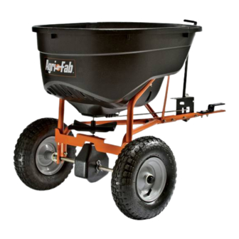
130 LB. Tow Spreader
ÉpaNdeUr reMorQUÉ de 130 LB. (59 KG)
• Sécurité
• Assemblage
• Utilisation
• Entretien
• Pièces
Want more information or assembly tips?
Scan with free ShowUHow Mobile App
available at iTunes Store or Android Market.
Call 1-800-448-9282 for missing parts or assembly help.
• Seguridad
• Montaje
• Operación
• Mantenimiento
• Piezas de repuesto
FORM NO. 42313 rev. (1/3/12)
Advertisement
Table of Contents

Related Manuals for Agri-Fab 45-04631


Summary of Contents for Agri-Fab 45-04631
- Page 1 ™ owNerS MaNUaL NoTICe d’UTILISaTIoN MaNUaL deL USUarIo Model No. Modèle No. Modelo No. 45-04631 130 LB. Tow Spreader ÉpaNdeUr reMorQUÉ de 130 LB. (59 KG) CAUTION: eSparCIdor de reMoLQUe de 130 LBS. (59 KG) Read Rules for Safe Operation...
-
Page 2: Safety Rules
SaFeTY rULeS Remember, any power equipment can cause injury if operated improperly or if the user does not understand how to operate the equipment. Exercise caution at all times when using power equipment. Look for this symbol to point out CaUTIoN: vehicle braking and stability important safety precautions. - Page 3 SHowN FULL SIZe NoT SHowN FULL SIZe Hardware paCKaGe reF QTY parT No deSCrIpTIoN reF QTY parT No deSCrIpTIoN R19212016 Washer, 5/8" 47623 Hitch Pin 49870 Hex Bolt, 1/4" x 2-1/2" 44101 Cotter Pin, 3/32" x 3/4" 43093 Cotter Pin, 1/8" x 1-1/2" 46699 Hex Bolt, 1/4"...
-
Page 4: Tools Required For Assembly
aSSeMBLY INSTrUCTIoNS STep 3: (See FIGUre 3) • Insert plugs (AA) into the ends of the hopper support tubes (5) and (6). TooLS reQUIred For aSSeMBLY • Attach hopper support tube (5) and hopper support tube (6) to the hitch support tubes as shown, using (1) Hammer two 1/4"... - Page 5 STep 5: STep 7: (See FIGUre 5) (See FIGUre 7) • Install the gearbox by inserting the end of the verticle • Place the hopper on the hopper support tubes, shaft into the cross brace bushing and inserting the inserting the spreader shaft up through the square axle into the ends of the hopper support tubes.
- Page 6 STep 9: STep 11: (See FIGUre 11) (See FIGUre 9) • Install the grip (BB) onto the flow control arm. • Install the end of the flow control rod (10) with no hole into the elongated hole in the flow plate on the bottom • Assemble the adjustable stop (V) to the flow control bracket using the 1/4" x 3/4" carriage bolt (H), nylon of the hopper. Lock the rod in the flow plate by rotating washer (N) and wing nut (U). the rod. FIGUre 9 FIGUre 11 STep 10: STep 12: (See FIGUre 10)
- Page 7 STep 13: STep 16: (See FIGUre 13) (See FIGUre 15) • Fasten the hopper braces (11) to the hopper support • Slide a 5/8" washer (O), a spacer (L), a 5/8" washer tubes using the nylock nuts (J) that were assembled (O) and a wheel onto the end of the axle with a hole.
-
Page 8: Operation
operaTIoN 10. Heavy moisture conditions may require use of a vinyl hopper cover to keep contents dry. The cover acts as a wind and moisture shield, but should not be used as a rain cover. The #41316 cover can be ordered as an How To USe YoUr Spreader option. -
Page 9: Maintenance
MaINTeNaNCe SerVICe aNd adJUSTMeNTS 1. If the axle and gear assembly is disassembled, mark CHeCK For LooSe FaSTeNerS down the positions of the parts as they are removed. 1. Before each use, make a thorough visual check of the The drive wheel and large gear positions, in relation spreader for any bolts and nuts which may have to the small gear, determine which direction the loosened. -
Page 10: Consignes De Sécurité
FraNÇaIS CoNSIGNeS de SÉCUrITÉ N’oubliez pas qu’un matériel motorisé peut causer des blessures s’il est mal utilisé ou si son utilisateur ne comprend pas comment s’en servir. Agissez avec précaution en permanence quand vous utilisez un matériel motorisé. aTTeNTIoN : Le freinage et la stabilité du Ce symbole indique les précautions de sécurité... - Page 11 ÉTape 3 : (VoIr La FIGUre 3) ÉTape 10 : (VoIr La FIGUre 10) • Insérez les obturateurs (AA) dans les extrémités des tubes- • Fixez le support de contrôle du débit au tube d'attelage supports de la trémie (5) et (6). à...
- Page 12 UTILISaTIoN 10. Par forte humidité, il pourra être nécessaire d’utiliser un couvercle en vinyle sur la trémie pour garder son chargement au sec. Le couvercle protège contre le vent et CoMMeNT UTILISer VoTre ÉpaNdeUr aÉraTeUr l’humidité, mais n'est pas prévu pour protéger de la pluie. On rÉGLaGe dU dÉBIT peut commander le couvercle N°...
-
Page 13: Entretien
eNTreTIeN SerVICe eT rÉGLaGeS En cas de démontage de l’essieu et du réducteur, marquez VÉrIFIeZ Le BoN SerraGe de La VISSerIe les positions des pièces au fur et à mesure de leur Avant chaque utilisation, effectuez une vérification visuelle démontage. Les positions de la roue dentée d’entraînement approfondie de l’épandeur, pour vérifiez qu’aucun boulon et du grand pignon par rapport au petit pignon déterminent ou écrou n’est desserré. -
Page 14: Reglas De Seguridad
eSpaÑoL reGLaS de SeGUrIdad Recuerde que los equipos eléctricos pueden causar lesiones si no se operan correctamente o si el usuario no sabe cómo operar el equipo. preCaUCIÓN: El sistema de freno y la Preste atención a este símbolo ya que indica estabilidad del vehículo pueden verse afectados precauciones de seguridad importantes. Significa con la adición de un accesorio. - Page 15 paSo 2: (Vea La FIGUra 2) paSo 10: (Vea La FIGUra 10) • Acople los tubos de soporte (4) e (3) del enganche al tubo • Acople el soporte de control de flujo al tubo de la tolva de soporte usando un perno hexagonal de 1/4 pulg. x 2 usando dos pernos hexagonales de 1/4 pulg. x 1-3/4 pulg. pulg.
-
Page 16: Operación
operaCIÓN 10. En condiciones de bastante humedad puede requerirse el uso de una cubierta de vinilo para tolva a fin de que el contenido se mantenga seco. La cubierta funciona como un ForMa de USar eL eSparCIdor protector contra el viento y la humedad, pero no debe usarse GradUaCIoN deL CoNTroL de FLUJo como cubierta para proteger contra la lluvia. -
Page 17: Mantenimiento
MaNTeNIMIeNTo SerVICIo Y aJUSTeS VerIFIQUe QUe No HaYaN SUJeTadoreS FLoJoS Si desensambla el eje y los engranajes, marque las ubicaciones de las piezas a medida que las retira. Las Antes de cada uso, haga una inspección visual completa ubicaciones de la rueda de dirección y el engranaje del esparcidor para verificar que no hayan pernos y tuercas grande, en relación al engranaje pequeño, determinan en flojos. Vuelva a ajustar los pernos y tuercas flojos. - Page 18 For 45-04631 130 LB. Tow Spreader...
- Page 19 For 45-04631 130 LB. Tow Spreader reF QTY parT No deSCrIpTIoN reF QTY parT No deSCrIpTIoN 41084 Hopper 26711 Shaft, Spreader 40880 Wheel 47212 Housing, Large Gear 42009 Tube, Hitch Support 44125 Washer, .625 x 1.0 x .03...
-
Page 20: Repair Parts
Agri-Fab, Inc. Unauthorized uses and/or reproductions of this manual will subject such unauthorized user to civil and criminal penalties as provided by the United States Copyright Laws.
Need help?
Do you have a question about the 45-04631 and is the answer not in the manual?
Questions and answers