Dell DR4100 Owner's Manual
Disk backup system
Hide thumbs
Also See for DR4100:
- Best practices manual (41 pages) ,
- Manual (27 pages) ,
- Qiuck setup (1 page)

Related Manuals for Dell DR4100


Summary of Contents for Dell DR4100
- Page 1 Dell DR4100 Systems Owner's Manual Regulatory Model: E14S Series Regulatory Type: E14S001...
- Page 2 CAUTION: A CAUTION indicates either potential damage to hardware or loss of data and tells you how to avoid the problem. WARNING: A WARNING indicates a potential for property damage, personal injury, or death. © 2013 Dell Inc. Trademarks used in this text: Dell , the Dell logo, Dell Boomi , Dell Precision , OptiPlex...
-
Page 3: Table Of Contents
Contents 1 About Your System........................7 ........................7 Front-Panel Features And Indicators ..............................8 Diagnostic Indicators ..........................10 Hard-Drive Indicator Patterns ........................11 Back-Panel Features And Indicators ..............................12 NIC Indicator Codes ............................13 Power Indicator Codes ...........................14 Other Information You May Need 2 Using The System Setup And Boot Manager...............15 ............................15 Entering System Setup... - Page 4 ..............................29 Inside The System ............................. 30 Front Bezel (Optional) ..........................30 Removing The Front Bezel ..........................31 Installing The Front Bezel ...........................31 Opening And Closing The System ............................31 Opening The System ............................32 Closing The System ............................... 32 Cooling Shroud ......................... 32 Removing The Cooling Shroud ..........................
- Page 5 ............... 53 Installing An Expansion Card Into The Expansion-Card Riser 2 Or 3 ..............54 Removing An Expansion Card From The Expansion-Card Riser 1 ...............55 Installing An Expansion Card Into The Expansion-Card Riser 1 ........................56 Removing Expansion-Card Risers ........................59 Installing Expansion-Card Risers ............................
- Page 6 Troubleshooting A Storage Controller .......................... 90 Troubleshooting Expansion Cards ...........................91 Troubleshooting Processors 5 Using System Diagnostics....................... 93 ........................93 Dell Embedded System Diagnostics ..................93 When To Use The Embedded System Diagnostics ....................93 Running The Embedded System Diagnostics ..........................93 System Diagnostic Controls 6 Jumpers And Connectors......................
-
Page 7: About Your System
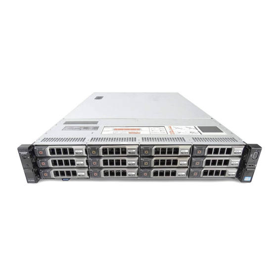
About Your System Front-Panel Features And Indicators The following topic describes the front-panel features and indicators of the Dell DR4100 system. Figure 1. Front-Panel Features and Indicators Item Indicator, Button, or Icon Description Connector Diagnostic indicators The diagnostic indicators light up to display error status. -
Page 8: Diagnostic Indicators
Item Indicator, Button, or Icon Description Connector Use this button only if directed to do so by qualified support personnel or by the operating system's documentation. Up to twelve 3.5 inch hot-swappable hard drives. Hard drives Video connector Allows you to connect a VGA display to the system. USB connector Allows you to connect USB devices to the system. - Page 9 Hard-drive indicator Condition Corrective Action 4. If the hard drives are configured in a RAID array, restart the system and enter the host adapter configuration utility program. Electrical indicator Condition Corrective Action The indicator blinks See the System Event Log or System Messages for the specific amber if the system...
-
Page 10: Hard-Drive Indicator Patterns
Help. experiences an error. Hard-Drive Indicator Patterns The following topic describes the hard-drive indicator patterns of the Dell DR4100 system. Figure 2. Hard-Drive Indicators 1. hard-drive activity indicator (green) 2. hard-drive status indicator (green and amber) NOTE: If the hard drive is in Advanced Host Controller Interface (AHCI) mode, the status indicator (on the right side) does not function and remains off. -
Page 11: Back-Panel Features And Indicators
Rebuild aborted seconds, amber three seconds, and off six seconds Back-Panel Features And Indicators The following topic describes the back-panel features and indicators of the Dell DR4100 system. Figure 3. Back-Panel Features And Indicators Item Indicator, Button, or Icon Description... -
Page 12: Nic Indicator Codes
NOTE: The vFlash media card slot is not active on the DR4100. Do not use this slot. NIC Indicator Codes The following topic describes the NIC indicator codes of the Dell DR4100 system. Figure 4. NIC Indicator 1. link indicator 2. -
Page 13: Power Indicator Codes
Indicator Indicator Code Link indicator is The NIC is connected to a valid network at less than its maximum port speed. amber Activity indicator is Network data is being sent or received. blinking green Power Indicator Codes Each AC power supply has an illuminated translucent handle that serves as an indicator to show whether power is present or whether a power fault has occurred. -
Page 14: Other Information You May Need
• For the full name of an abbreviation or acronym used in this document, see the Glossary at dell.com/support/ manuals. NOTE: Always check for updates on www.dell.com/support/manuals and read the updates first because they often... -
Page 15: Using The System Setup And Boot Manager
Enters the System Setup. <F10> Opens the Dell Lifecycle Controller 2 (LC2). The Dell LC2 supports systems management features such as firmware updates, hardware configuration, OS deployment, platform restore, and hardware diagnostics using a graphical user interface. The exact LC2 feature set is determined by the iDRAC license purchased. -
Page 16: Responding To Error Messages
Responding To Error Messages If an error message is displayed while the system is booting, make a note of the message. For more information, see System Error Messages. NOTE: After installing a memory upgrade, it is normal for your system to display a message the first time you start your system. -
Page 17: System Information Screen
NOTE: System Setup defaults are listed under their respective options in the following sections, where applicable. Menu Item Description System Information Displays information about the system such as the system model name, BIOS version, Service Tag, and so on. Memory Settings Displays information and options related to installed memory. -
Page 18: Processor Settings Screen
Menu Item Description Video Memory Displays the amount of video memory. System Memory Specifies whether system memory tests are run during system boot. Options are Enabled and Testing Disabled. By default, the System Memory Testing option is set to Disabled. Memory Operating Specifies the memory operating mode. -
Page 19: Boot Settings Screen
Menu Item Description Execute Disable Allows you enable or disable execute disable memory protection technology. By default, the Execute Disable option is set to Enabled. Logical Processor Allows you to enable or disable the OS capability to put logical processors in the idling state in Idling order to reduce power consumption. -
Page 20: Integrated Devices Screen
Integrated Devices Screen Menu Item Description Integrated RAID Allows you to enable or disable the integrated RAID controller. By default, the Integrated RAID Controller Controller option is set to Enabled. User Accessible USB Allows you enable or disable the user accessible USB ports. Selecting Only Back Ports On Ports disables the front USB ports and selecting All Ports Off disables both front and back USB ports. -
Page 21: System Profile Settings Screen
Custom. By default, the System Profile option is set to Performance Per Watt Optimized (DAPC). DAPC is Dell Active Power Controller. NOTE: The following parameters are available only when the System Profile is set to Custom. -
Page 22: System Security Screen
Menu Item Description NOTE: This option can be disabled only if the C States option in Custom mode is disabled. NOTE: When C States is enabled in Custom mode, changing the Monitor/Mwait setting does not impact system power/performance. Memory Patrol Scrub Allows you to set the memory patrol scrub frequency. By default, the Memory Patrol Scrub option is set to Standard. -
Page 23: Miscellaneous Settings
BIOS updates, it is recommended to set this field to Disabled. By default, the BIOS Update Control option is set to Unlocked. NOTE: BIOS updates using Dell Update Package are not affected by this option. Power Button Allows you to enable or disable the power button on the front of the system. -
Page 24: Assigning A System And/Or Setup Password
Setup password This is the password that you must enter to access and make changes to the BIOS or UEFI settings of your system. CAUTION: The password features provide a basic level of security for the data on your system. CAUTION: Anyone can access the data stored on your system if the system is running and unattended. -
Page 25: Using Your System Password To Secure Your System
To delete or change the existing System and/or Setup password: To enter System Setup, press <F2> immediately after a power-on or reboot. In the System Setup Main Menu, select System BIOS and press <Enter>. The System BIOS screen is displayed. In the System BIOS screen, select System Security and press <Enter>. -
Page 26: Using The Boot Manager Navigation Keys
Displays a list of the drivers installed on the system and their health status. Launch System Setup Enables you to access the System Setup. System Utilities Enables you to access the BIOS Update File Explorer, run the Dell Diagnostics program, and reboot the system. Embedded System Management The Dell Lifecycle Controller provides advanced embedded systems management throughout the server’s lifecycle. -
Page 27: Idrac Settings Utility
NOTE: Accessing some of the features on the iDRAC Settings utility requires the iDRAC7 Enterprise License upgrade. iDRAC7 User's Guide under Software → Systems Management → Dell For more information on using iDRAC, see the Remote Access Controllers, at dell.com/support/manuals. -
Page 29: Installing System Components
Damage due to servicing that is not authorized by Dell is not covered by your warranty. Read and follow the safety instructions that came with the product. -
Page 30: Front Bezel (Optional)
Figure 6. Inside the System 1. cooling-fan assembly 8. expansion-card riser 2 2. cable securing bracket 9. expansion-card riser 1 3. cooling shroud 10. heat sink for processor 1 4. hard-drive backplane (back) 11. heat sink for processor 2 5. hard drives (back) (2) 12. -
Page 31: Installing The Front Bezel
Damage due to servicing that is not authorized by Dell is not covered by your warranty. Read and follow the safety instructions that came with the product. -
Page 32: Closing The System
Damage due to servicing that is not authorized by Dell is not covered by your warranty. Read and follow the safety instructions that came with the product. -
Page 33: Installing The Cooling Shroud
Damage due to servicing that is not authorized by Dell is not covered by your warranty. Read and follow the safety instructions that came with the product. -
Page 34: System Memory
System Memory Your system supports DDR3 registered DIMMs (RDIMMs) and meets the DDR3 and DDR3L voltage specifications. NOTE: MT/s indicates DIMM speed in MegaTransfers per second. Memory bus operating frequency can be 1600 MT/s, 1333 MT/s, 1066 MT/s, or 800 MT/s depending on: •... - Page 35 Figure 10. Memory Socket Locations Memory channels are organized as follows: Processor 1 channel 0: slots A1, A5, and A9 channel 1: slots A2, A6, and A10 channel 2: slots A3, A7, and A11 channel 3: slots A4, A8, and A12 Processor 2 channel 0: slots B1, B5, and B9 channel 1: slots B2, B6, and B10...
-
Page 36: General Memory Module Installation Guidelines
General Memory Module Installation Guidelines This system supports Flexible Memory Configuration, enabling the system to be configured and run in any valid chipset architectural configuration. The following are the recommended guidelines for best performance: • x4 and x8 DRAM based DIMMs can be mixed. For more information, see Mode-Specific Guidelines. -
Page 37: Memory Configuration
Damage due to servicing that is not authorized by Dell is not covered by your warranty. Read and follow the safety instructions that came with the product. -
Page 38: Installing Memory Modules
CAUTION: To ensure proper system cooling, memory-module blanks must be installed in any memory socket that is not occupied. Remove memory-module blanks only if you intend to install memory in those sockets. Turn off the system, including any attached peripherals, and disconnect the system from the electrical outlet and peripherals. -
Page 39: Hard Drives
Damage due to servicing that is not authorized by Dell is not covered by your warranty. Read and follow the safety instructions that came with the product. -
Page 40: Removing A 2.5 Inch Hard-Drive Blank (Back)
When you format a hard drive, allow enough time for the formatting to be completed. Be aware that high-capacity hard drives can take a number of hours to format. Removing A 2.5 Inch Hard-Drive Blank (Back) CAUTION: To maintain proper system cooling, all empty hard-drive slots must have drive blanks installed. Pull the hard-drive blank out until it is free of the hard-drive slot. -
Page 41: Installing A 3.5 Inch Hard-Drive Blank
Figure 13. Removing and Installing a 3.5 Inch Hard-Drive Blank 1. hard-drive blank 2. release button Installing A 3.5 Inch Hard-Drive Blank If installed, remove the front bezel. Insert the hard-drive blank into the hard-drive slot until the release button clicks into place. If applicable, install the front bezel. -
Page 42: Installing A Hot-Swap Hard Drive
Damage due to servicing that is not authorized by Dell is not covered by your warranty. Read and follow the safety instructions that came with the product. -
Page 43: Removing A Hard Drive From A Hard-Drive Carrier
Damage due to servicing that is not authorized by Dell is not covered by your warranty. Read and follow the safety instructions that came with the product. -
Page 44: Removing A Cooling Fan
Damage due to servicing that is not authorized by Dell is not covered by your warranty. Read and follow the safety instructions that came with the product. -
Page 45: Installing A Cooling Fan
Damage due to servicing that is not authorized by Dell is not covered by your warranty. Read and follow the safety instructions that came with the product. -
Page 46: Installing The Cooling-Fan Assembly
Damage due to servicing that is not authorized by Dell is not covered by your warranty. Read and follow the safety instructions that came with the product. -
Page 47: Pcie Card Holder
Damage due to servicing that is not authorized by Dell is not covered by your warranty. Read and follow the safety instructions that came with the product. -
Page 48: Installing The Pcie Card Holder
Damage due to servicing that is not authorized by Dell is not covered by your warranty. Read and follow the safety instructions that came with the product. -
Page 49: Opening And Closing The Pcie Card Holder Latch
Damage due to servicing that is not authorized by Dell is not covered by your warranty. Read and follow the safety instructions that came with the product. -
Page 50: Removing The Cable Retention Bracket
Damage due to servicing that is not authorized by Dell is not covered by your warranty. Read and follow the safety instructions that came with the product. -
Page 51: Expansion Cards And Expansion-Card Risers
Full Length NOTE: To use PCIe slots 1 through 4 on the riser, both the processors must be installed. NOTE: DR4100 does not support riser 3 (default). NOTE: The expansion-card slots are not hot-swappable. The following table provides guidelines for installing expansion cards to ensure proper cooling and mechanical fit. The expansion cards with the highest priority must be installed first using the slot priority indicated. -
Page 52: Removing An Expansion Card From The Expansion-Card Riser 2 Or 3
Damage due to servicing that is not authorized by Dell is not covered by your warranty. Read and follow the safety instructions that came with the product. -
Page 53: Installing An Expansion Card Into The Expansion-Card Riser 2 Or 3
Damage due to servicing that is not authorized by Dell is not covered by your warranty. Read and follow the safety instructions that came with the product. -
Page 54: Removing An Expansion Card From The Expansion-Card Riser 1
Damage due to servicing that is not authorized by Dell is not covered by your warranty. Read and follow the safety instructions that came with the product. -
Page 55: Installing An Expansion Card Into The Expansion-Card Riser 1
Damage due to servicing that is not authorized by Dell is not covered by your warranty. Read and follow the safety instructions that came with the product. -
Page 56: Removing Expansion-Card Risers
Damage due to servicing that is not authorized by Dell is not covered by your warranty. Read and follow the safety instructions that came with the product. - Page 57 Figure 25. Identifying Connectors on the Expansion Card Riser 1 1. expansion-card slot 1 2. expansion-card slot 2 3. expansion-card slot 3 Figure 26. Removing and Installing the Expansion Card Riser 2 1. expansion-card riser 2 2. riser guide (back) 3.
- Page 58 Figure 27. Identifying Connectors on the Expansion Card Riser 2 1. chassis intrusion switch 2. expansion-card slot 4 3. expansion-card slot 5 Figure 28. Removing and Installing the Expansion Card Riser 3 1. riser guide (front) 2. expansion-card riser 3 3.
-
Page 59: Installing Expansion-Card Risers
Damage due to servicing that is not authorized by Dell is not covered by your warranty. Read and follow the safety instructions that came with the product. - Page 60 Remove the expansion-card riser 3 and any card(s) installed in the riser. Locate the internal dual SD module installed on the J_IDSDM connector on the system board. If applicable, remove the SD card(s). Holding the tab, pull the dual SD module to remove it from the system board. Replace the expansion-card riser 3 and if applicable, replace the card(s) in the riser.
-
Page 61: Installing The Internal Dual Sd Module
Damage due to servicing that is not authorized by Dell is not covered by your warranty. Read and follow the safety instructions that came with the product. -
Page 62: Installing The Integrated Storage Controller Card
Damage due to servicing that is not authorized by Dell is not covered by your warranty. Read and follow the safety instructions that came with the product. -
Page 63: Network Daughter Card
Damage due to servicing that is not authorized by Dell is not covered by your warranty. Read and follow the safety instructions that came with the product. -
Page 64: Installing The Network Daughter Card
Damage due to servicing that is not authorized by Dell is not covered by your warranty. Read and follow the safety instructions that came with the product. - Page 65 Loosen the second heat-sink retention socket. Lift the heat sink away from the processor and set the heat sink aside. Figure 33. Removing and Installing the Processor Heat Sink 1. heat sink 2. retention sockets (2) 3. retention screws (2) 4.
- Page 66 Figure 34. Processor Shield Opening and Closing Lever Sequence 1. close-lock symbol 4. processor socket-release lever 2. processor socket-release lever 5. open-lock symbol 3. processor 10. Rotate the processor shield upward and out of the way. CAUTION: The socket pins are fragile and can be permanently damaged. Be careful not to bend the pins in the socket when removing the processor out of the socket.
-
Page 67: Installing A Processor
Damage due to servicing that is not authorized by Dell is not covered by your warranty. Read and follow the safety instructions that came with the product. -
Page 68: Power Supplies
Remove the cooling shroud. WARNING: The heat sink and processor are hot to the touch for some time after the system has been powered down. Allow the heat sink and processor to cool before handling them. CAUTION: Never remove the heat sink from a processor unless you intend to remove the processor. The heat sink is necessary to maintain proper thermal conditions. -
Page 69: Power Supply Hot Spare Feature
Damage due to servicing that is not authorized by Dell is not covered by your warranty. Read and follow the safety instructions that came with the product. -
Page 70: Installing An Ac Power Supply
Damage due to servicing that is not authorized by Dell is not covered by your warranty. Read and follow the safety instructions that came with the product. -
Page 71: Installing The Power Supply Blank
Damage due to servicing that is not authorized by Dell is not covered by your warranty. Read and follow the safety instructions that came with the product. -
Page 72: Hard-Drive Backplane
Damage due to servicing that is not authorized by Dell is not covered by your warranty. Read and follow the safety instructions that came with the product. - Page 73 CAUTION: You must note the number of each hard drive and temporarily label them before removal so that you can replace them in the same locations. Remove the cooling shroud. Remove the cooling-fan assembly. Remove all hard drives. Disconnect the SAS data, signal, and power cable(s) from the backplane. Press the release tabs and slide the backplane upward.
-
Page 74: Installing The Hard-Drive Backplane
Damage due to servicing that is not authorized by Dell is not covered by your warranty. Read and follow the safety instructions that came with the product. -
Page 75: Removing The Hard-Drive Backplane (Back)
Damage due to servicing that is not authorized by Dell is not covered by your warranty. Read and follow the safety instructions that came with the product. - Page 76 1. pass-through I2C cable 5. SAS connectors (2) 2. I2C cable 6. SAS cable 3. sideband cable 7. release pin 4. hard-drive backplane (back) Figure 42. Cabling Diagram—Optional 2.5 Inch (x2) Hard-Drive Backplane (back) 1. PCIe card holder 5. SAS connector on the system board 2.
-
Page 77: Installing The Hard-Drive Backplane (Back)
Damage due to servicing that is not authorized by Dell is not covered by your warranty. Read and follow the safety instructions that came with the product. -
Page 78: Installing The I/O Panel
Damage due to servicing that is not authorized by Dell is not covered by your warranty. Read and follow the safety instructions that came with the product. -
Page 79: System Board
Damage due to servicing that is not authorized by Dell is not covered by your warranty. Read and follow the safety instructions that came with the product. - Page 80 a. mini SAS cable connector b. metal tab c. connector on the system board Disconnect all cables from the system board. CAUTION: Take care not to damage the system identification button while removing the system board from the chassis. CAUTION: Do not lift the system board assembly by grasping a memory module, processor, or other components.
-
Page 81: Installing The System Board
Damage due to servicing that is not authorized by Dell is not covered by your warranty. Read and follow the safety instructions that came with the product. -
Page 83: Troubleshooting Your System
Damage due to servicing that is not authorized by Dell is not covered by your warranty. Read and follow the safety instructions that came with the product. -
Page 84: Troubleshooting A Serial I/O Device
Power down all attached USB devices and disconnect them from the system. Restart the system and, if your keyboard is functioning, enter the System Setup. Verify that all USB ports are enabled on the Integrated Devices screen, in the System Setup options. If your keyboard is not functioning, you can also use remote access. -
Page 85: Troubleshooting A Wet System
Damage due to servicing that is not authorized by Dell is not covered by your warranty. Read and follow the safety instructions that came with the product. -
Page 86: Troubleshooting The System Battery
Damage due to servicing that is not authorized by Dell is not covered by your warranty. Read and follow the safety instructions that came with the product. -
Page 87: Troubleshooting Cooling Problems
Damage due to servicing that is not authorized by Dell is not covered by your warranty. Read and follow the safety instructions that came with the product. -
Page 88: Troubleshooting An Internal Usb Key
Damage due to servicing that is not authorized by Dell is not covered by your warranty. Read and follow the safety instructions that came with the product. -
Page 89: Troubleshooting A Hard Drive
Damage due to servicing that is not authorized by Dell is not covered by your warranty. Read and follow the safety instructions that came with the product. -
Page 90: Troubleshooting A Storage Controller
Damage due to servicing that is not authorized by Dell is not covered by your warranty. Read and follow the safety instructions that came with the product. -
Page 91: Troubleshooting Processors
Damage due to servicing that is not authorized by Dell is not covered by your warranty. Read and follow the safety instructions that came with the product. -
Page 93: Using System Diagnostics
Using System Diagnostics If you experience a problem with your system, run the system diagnostics before contacting Dell for technical assistance. The purpose of running system diagnostics is to test your system hardware without requiring additional equipment or risking data loss. If you are unable to fix the problem yourself, service and support personnel can use the diagnostics results to help you solve the problem. - Page 94 Displays a time-stamped log of the results of all tests run on the system. This is displayed if at least one event description is recorded. Dell Enhanced Pre-boot System Assessment User Guide at For information about embedded system diagnostics, see the...
-
Page 95: Jumpers And Connectors
Jumpers And Connectors System Board Jumper Settings For information on resetting the password jumper to disable a password, see Disabling A Forgotten Password. Table 4. System Board Jumper Settings Jumper Setting Description PWRD_EN The password feature is enabled (pins 4–6). (default) The password feature is disabled (pins 2–4). -
Page 96: System Board Connectors
System Board Connectors Figure 45. System Board Jumpers and Connectors Item Connector Description J_PS2 PSU 2 power connector J_SATA_CD Optical drive SATA connector J_SATA_TBU Tape backup unit SATA connector J_BP0 Optical drive power connector J_TBU Tape backup unit power connector J_PS1 PSU 1 power connector J_IDSDM... - Page 97 Item Connector Description J_VIDEO_REAR Video connector J_COM1 Serial connector J_IDRAC_RJ45 iDRAC7 connector J_CYC System identification connector CYC_ID System identification button J_RISER_2A Riser 2 connector J_RISER_1A Riser 1 connector J_RISER_2B Riser 2 connector J_RISER_1B Riser 1 connector J_STORAGE Integrated storage controller card connector J_SASX8 Mini SAS connector J_USB_INT...
-
Page 98: Disabling A Forgotten Password
Damage due to servicing that is not authorized by Dell is not covered by your warranty. Read and follow the safety instructions that came with the product. -
Page 99: Technical Specifications
Technical Specifications Processor Processor type One or two Intel Xeon processor E5-2600 product family Power AC Power Supply (per power supply) Wattage 750 W 2891 BTU/hr (maximum) Heat dissipation NOTE: Heat dissipation is calculated using the power supply wattage rating. Voltage 100–240 V AC, autoranging, 50/60 Hz NOTE: This system is also designed to be... - Page 100 Memory Architecture 800 MT/s, 1066 MT/s, 1333 MT/s or 1600 MT/s DDR3 registered Error Correcting Code (ECC) DIMMs Support for advanced ECC or memory optimized operation Memory module sockets Twenty-four 240-pin Memory module capacities 8 GB dual ranked RDIMMs 32 GB with two processors Drives Hard drives Up to twelve 3.5 inch, internal, hot-swappable, Nearline SAS...
- Page 101 • 130 W (4 core) processor is not supported. • Redundant power supplies are required. • Non Dell qualified peripheral cards and/or peripheral cards greater than 25 W are not supported. • Maximum 95 W processor supported on 3.5 inch hard drive chassis.
- Page 102 Environmental Humidity Percentage Range 10% to 80% Relative Humidity with 26 °C (78.8 °F) maximum dew point. Relative Humidity Storage 5% to 95% RH with 33 °C (91 °F) maximum dew point. Atmosphere must be non-condensing at all times. Maximum Vibration Operating 0.26 G at 5 Hz to 350 Hz (all operation orientations).
- Page 103 Environmental Conductive Dust Air must be free of conductive dust, zinc whiskers, or other conductive particles. NOTE: Applies to data center and non-data center environments. Corrosive Dust • Air must be free of corrosive dust. • Residual dust present in the air must have a NOTE: Applies to data center and non-data center deliquescent point less than 60% relative environments.
-
Page 105: System Messages
System Messages System Error Messages System messages appear on the monitor to notify you of a possible problem with the system. These messages refer to events recorded in the System Event Log (SEL). For information on the SEL and configuring system management settings, see the systems management software documentation. - Page 106 Error Code Message Information Action Check the operating system, application, hardware, and system event log for exception events. ASR0001 Message The watchdog timer reset the system. Details The operating system or an application failed to communicate within the time-out period. The system was reset. Action Check the operating system, application, hardware, and system event log for exception events.
- Page 107 Error Code Message Information Details The processor temperature increased beyond the operational range. Action Review the logs for fan failures. If no fan failures are detected, check inlet temperature (if available) and reinstall processor heat sink. If the problem persists, see Getting Help.
- Page 108 Error Code Message Information Action 1. Check system and operating system logs for exceptions. If no exceptions are found, continue. 2. Turn off the system and remove input power for one minute. 3. Ensure the processor is seated correctly. 4. Reapply input power and turn on the system. 5.
- Page 109 Error Code Message Information 5. If the issue persists, see Getting Help. FAN0000 number > RPM is less than the lower warning threshold. Message Fan < Details Fan operating speed is out of range. Action Remove and reinstall the fan. If the issue persists, see Getting Help.
- Page 110 Error Code Message Information MEM0001 Message Multi-bit memory errors detected on a memory device at location(s) location >. < Details The memory module has encountered an uncorrectable error. System performance may be degraded. The operating system and/or applications may fail as a result. Action Re-seat the memory modules.
- Page 111 Error Code Message Information MEM8000 Message Correctable memory error logging disabled for a memory device at location >. location < Details Errors are being corrected but no longer logged. Action Review system logs for memory exceptions. Reinstall memory at location >. location <...
- Page 112 Error Code Message Information Details System performance may be degraded, or system may fail to operate. Action Cycle input power, update component drivers, if device is removable, reinstall the device. PCI1360 number >. Message A bus fatal error was detected on a component at slot < Details System performance may be degraded, or system may fail to operate.
- Page 113 Error Code Message Information Details System performance and power redundancy may be degraded or lost. Action Remove and reinstall the power supply at the next service window. If the issue persists, see Getting Help. PSU0003 number > is lost. Message The power input for power supply <...
- Page 114 Error Code Message Information PSU0033 number > is outside of the Message The temperature for power supply < allowable range. Details System performance may be degraded. Action Check the system operating environment, including airflow and inlet temperature. Check system logs for temperature and thermal component failures.
- Page 115 Error Code Message Information PSU1201 Message Power supply redundancy is lost. Details The power supply tries to operate in a degraded state. System Performance and power redundancy may be degraded or lost. Action Check input power. Reinstall the power supply. If the issue persists, Getting Help.
- Page 116 Error Code Message Information RFM1014 name > is write protected. Message Removable Flash Media < Details The card is write-protected by the physical latch on the SD card. A write-protected card cannot be used. Action If unintended, remove the media and disable write protection. RFM1201 Message Internal Dual SD Module redundancy is lost.
- Page 117 Error Code Message Information Details The chassis was opened while the power was off. System security may have been compromised. Action Close the chassis and verify hardware inventory. Check system logs. SEL0006 Message All event logging is disabled. Details This message is displayed when all event logging has been disabled by the user.
-
Page 118: Warning Messages
Error Code Message Information Action Check the system operating environment. TMP0120 Message The system inlet temperature is greater than the upper warning threshold. Details Ambient air temperature is too warm or one or more fans may have failed. Action Check the system operating environment and review event log for fan failures. -
Page 119: Alert Messages
Alert Messages Systems management software generates alert messages for your system. Alert messages include information, status, warning, and failure messages for drive, temperature, fan, and power conditions. For more information, see the systems management software documentation. -
Page 121: Getting Help
Dell product catalog. Dell provides several online and telephone-based support and service options. Availability varies by country and product, and some services may not be available in your area. To contact Dell for sales, technical support, or customer service issues: Visit dell.com/support... -
Page 122: Documentation Feedback
Documentation Feedback If you have feedback for this document, write to documentation_feedback@dell.com. Alternatively, you can click on the Feedback link in any of the Dell documentation pages, fill up the form, and click Submit to send your feedback.
Need help?
Do you have a question about the DR4100 and is the answer not in the manual?
Questions and answers