Table of Contents
Advertisement
Quick Links
Advertisement
Table of Contents
Troubleshooting

Related Manuals for Cisco 901


Summary of Contents for Cisco 901
- Page 1 Cisco ASR 901 Series Aggregation Services Router Hardware Installation Guide December, 2012 Americas Headquarters Cisco Systems, Inc. 170 West Tasman Drive San Jose, CA 95134-1706 http://www.cisco.com Tel: 408 526-4000 800 553-NETS (6387) Fax: 408 527-0883 Text Part Number: OL-23778-01...
- Page 2 REPRESENTATIVE FOR A COPY. Cisco and the Cisco logo are trademarks or registered trademarks of Cisco and/or its affiliates in the U.S. and other countries. To view a list of Cisco trademarks, go to this URL: www.cisco.com/go/trademarks. Third-party trademarks mentioned are the property of their respective owners. The use of the word partner does not imply a partnership relationship between Cisco and any other company.
-
Page 3: Table Of Contents
C H A P T E R Safety Guidelines Safety with Equipment Safety with Electricity Preventing Electrostatic Discharge Damage Prerequisites Site Planning Power Supply Considerations Site Environment Air Flow Guidelines Cisco ASR 901 Series Aggregation Services Router Hardware Installation Guide OL-23778-01... - Page 4 3-15 Connecting to the Management Ethernet Port 3-15 Dressing Router Cables 3-15 Powering On the Router 3-15 Checklist for Power Up 3-16 Interpreting Front-Panel LEDs 3-16 Power-On Procedure 3-16 Cisco ASR 901 Series Aggregation Services Router Hardware Installation Guide OL-23778-01...
- Page 5 BITS Port Pinouts Time of Day Pinouts GPS Port Pinouts Alarm Port Pinouts Management Ethernet Port Pinouts Site Log A P P E N D I X N D E X Cisco ASR 901 Series Aggregation Services Router Hardware Installation Guide OL-23778-01...
- Page 6 Contents Cisco ASR 901 Series Aggregation Services Router Hardware Installation Guide OL-23778-01...
-
Page 7: About This Guide
Not all Cisco documents use a Document Revision History table. Revision Date Change Summary OL-23778-01 October 2011 Initial version of the document. OL-23778-01 February 2012 Updated T1/E1 Interface LEDs section in the Troubleshooting chapter. Cisco ASR 901 Series Aggregation Services Router Hardware Installation Guide OL-23778-01... -
Page 8: Objectives
Cisco IOS configuration guide and command reference publications. For more information, see “Obtaining Documentation, Obtaining Support, and Security Guidelines” section on page Warranty, service, and support information is in the Cisco Information Packet that is shipped with your router. -
Page 9: Safety Warnings
Statement 1071 SAVE THESE INSTRUCTIONS Related Documentation For additional information about the Cisco ASR 901 router, refer to the following documents: • Cisco Regulatory Compliance and Safety Information for Cisco ASR 901 Series Aggregation Services Router Cisco ASR 901 Series Aggregation Services Router Software Configuration Guide •... -
Page 10: Obtaining Documentation, Obtaining Support, And Security Guidelines
For information on obtaining documentation, obtaining support, providing documentation feedback, security guidelines, and also recommended aliases and general Cisco documents, see the monthly What’s New in Cisco Product Documentation, which also lists all new and revised Cisco technical documentation, at: http://www.cisco.com/en/US/docs/general/whatsnew/whatsnew.html... -
Page 11: Introduction
The Cisco ASR 901 Mobile Wireless Router is a cell site gateway platform specifically designed to provide transport for both legacy TDM and Ethernet traffic over a single converged network. The Cisco ASR 901 router is used at the cell site as a part of a 2G, 3G, or 4G radio access network (RAN) traffic. -
Page 12: Cisco Asr 901 Router Front View
– Cisco ASR 901 Router Front View Figure 1-1 shows the front view of the Cisco ASR 901 router with each interface module. The front panel of the Cisco ASR 901 router has the following components: • 16 T1/E1 ports, labelled T1/E1 (positions 1, 2, 3, 4, 5, 6, 7, 8, 9, 10, 11, 12, 13, 14,15 and 16) •... -
Page 13: Cisco Asr 901 Router Ethernet Version Front View
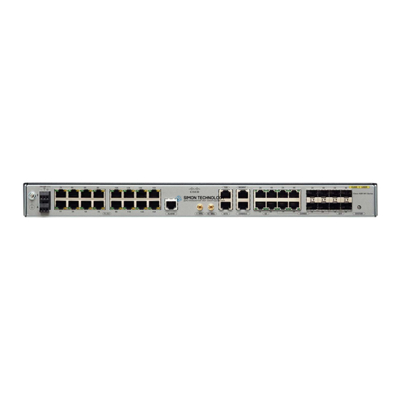
Figure 1-2 shows the front view of the Cisco ASR 901 router with each interface module. The front panel of the Cisco ASR 901 router, ethernet version has the following components: Eight RJ-45 jacks for copper Ethernet ports, labeled “100/1000” Ethernet. -
Page 14: Cisco Asr 901 Router Ethernet Version Front View
11 Power Connector Console Port Cisco ASR 901 Router Rear View Figure 1-3 shows the rear view of the Cisco ASR 901 router including the orientation of the following components: Two blowing fans • Mounting point for the 2-hole lug. For more information, see the Connecting the Chassis Ground •... -
Page 15: Leds
Chapter 1 Introduction Power Supply LEDs The Cisco ASR 901 chassis and interface modules contain LEDs to assist in troubleshooting. For more detailed description of the LEDs, see the “Reading the LEDs, page A-4. Power Supply The Cisco ASR 901 router is equipped with an internal -27/-72 volts Direct Current (VDC). - Page 16 Introduction Power Supply The Cisco ASR 901 router uses two 3 pin connectors (part number 27-2030-01) for input to the power supply. The terminal block is part of the accessory kit (part number 53-3085-01/53-3295-0), which ships with the Cisco ASR 901 router.
-
Page 17: Environmental Monitoring Temperature Sensor
Air Flow Router Interface Numbering Each network interface on a Cisco ASR 901 router is identified by a slot number and a port number, explained in this sequence: Logical slot numbers starts from 0 for all built-in interfaces. The numbering format is •... -
Page 18: Regulatory Compliance
T1/E1 interface module T1/E1 Power connector Onboard Power Connector Regulatory Compliance For regulatory compliance and safety information, see Cisco Regulatory Compliance and Safety Information for Cisco ASR 901 Series Aggregation Services Router. Cisco ASR 901 Series Aggregation Services Router Hardware Installation Guide OL-23778-01... -
Page 19: Chapter 2 Preparing To Install The Router
C H A P T E R Preparing to Install the Router This chapter describes site requirements and equipment used to install the Cisco ASR 901 router. It includes the following sections: Safety Guidelines, page 2-1 • Prerequisites, page 2-4 •... -
Page 20: Safety With Electricity
Before working on the system, switch off the DC main circuit breaker and disconnect the power • terminal block cable. Disconnect all power before performing the following: • Cisco ASR 901 Series Aggregation Services Router Hardware Installation Guide OL-23778-01... -
Page 21: Preventing Electrostatic Discharge Damage
If no wrist strap is available, ground yourself by touching a metal part of the chassis. For the safety of your equipment, periodically check the resistance value of the antistatic wrist strap. It Caution should be between 1 and 10 Mohm. Cisco ASR 901 Series Aggregation Services Router Hardware Installation Guide OL-23778-01... -
Page 22: Prerequisites
This equipment is designed for connection to TN and IT power systems. Statement 16 Site Environment Install the Cisco ASR 901 router in an equipment rack. The location of your router and the layout of your equipment rack, or wiring room are extremely important considerations for proper operation. Cramped equipment, inadequate ventilation, and inaccessible panels can cause malfunctions and shutdown, and can make maintenance difficult. -
Page 23: Air Flow Guidelines
Determine power requirements. Identify required procedures or tests. On an equipment plan, make a preliminary decision that locates each Cisco ASR 901 router that you plan to install. Verify the list of replaceable parts for installation (screws, bolts, washers, and so on) so that the parts are identified. -
Page 24: Unpacking And Checking The Contents Of Your Shipment
Note Do not discard the packaging materials used in shipping your Cisco ASR 901 router. You will need the packaging materials in the future if you move or ship the router. -
Page 25: Installation Checklist
Installation site power check completed Required tools available Additional equipment available Router received Documentation DVD received (if ordered) Cisco Information Packet publication received Chassis components verified Initial electrical connections established Cisco ASR 901 Series Aggregation Services Router Hardware Installation Guide OL-23778-01... -
Page 26: Creating A Site Log
(using a modem). The Cisco ASR 901 router uses only console port. Note Console and rollover cables are not included with the Cisco ASR 901 router. You can order the console Note cable from Cisco Systems, Inc. (Part number ACS-1900ASYN=). - Page 27 For cable and port pinouts, see the online document Cisco Modular Access Router Cable Specifications. This document is provided on the documentation DVD that accompanied your router (if ordered), and is also available online at Cisco.com. Cisco ASR 901 Series Aggregation Services Router Hardware Installation Guide OL-23778-01...
- Page 28 Chapter 2 Preparing to Install the Router Console Port Considerations Cisco ASR 901 Series Aggregation Services Router Hardware Installation Guide 2-10 OL-23778-01...
-
Page 29: Chapter 3 Installing The Cisco Asr 901 Mobile Wireless Router
C H A P T E R Installing the Cisco ASR 901 Mobile Wireless Router This chapter describes how to install the Cisco ASR 901 router, and how to connect it to networks and external devices. These are the following sections: •... -
Page 30: Mounting The Cisco Asr 901 Router
Caution Allow clearance on either side of the Cisco ASR 901 router for cooling air to be drawn in through the left side and circulated through the chassis and out the two fan exhaust ports mounted on the other side of the chassis. -
Page 31: Attaching The Rack-Mounting Brackets
Complete the following tasks to install, replace, or rearrange the rack-mounting brackets so you can then mount the Cisco ASR 901 router in a 19-inch (48.3-cm) equipment rack. You can use the same rack-mounting brackets to front-mount the Cisco ASR 901 router in the equipment rack. -
Page 32: Attaching The Cable Guides
Use the cable guides to dress the cables that attach to the front of the Cisco ASR 901 router. The cable guides allow you to gather the cables and direct them to the left and right sides of the router. This helps to keep the cables from obscuring the fronts of lower routers in the same rack. -
Page 33: Connecting The Chassis Ground And Power
Connecting the Chassis Ground and Power Before you connect power or turn on power to the Cisco ASR 901 router, you must provide an adequate chassis ground (earth) connection to your router. Grounding the Cisco ASR 901 Router The Cisco ASR 901 router provides a grounding point on the rear of the unit for a 2-hole lug. - Page 34 When installing the unit, the ground connection must always be made first and disconnected last. Warning Statement 42 Figure 3-3 shows the grounding point marked on the rear panel of the Cisco ASR 901 router for ease of installation Figure 3-3 Grounding Point...
-
Page 35: Power Connection Compliance
Before performing any of the following procedures, ensure that power is removed from the DC circuit. Warning Statement 1003 Use copper conductors only. Statement 1025 Warning The installation must comply with the 2002 National Electric Code (NEC) and other applicable codes. Note Cisco ASR 901 Series Aggregation Services Router Hardware Installation Guide OL-23778-01... -
Page 36: Wiring The Dc-Input Power Source
Locate the 6-pin terminal block (part number 27-2030-01) (Figure 3-6). The terminal block is located in Step 2 the accessory kit (part number 53-3085-01 for the Cisco ASR 901 router), which is shipped with the router. Figure 3-6 6-Pin Terminal Block Plug the 6-pin terminal block into the power connector located on the front side of the router. -
Page 37: Installing And Removing Sfp Modules
SFP module slots on the front of the Cisco ASR 901 router. These field-replaceable modules provide interfaces. See the Release Notes for Cisco ASR 901 Series Aggregation Services Router for the list of supported SFP modules. Each port must match the wavelength specifications on the other end of the cable. For reliable communications, the cable must not exceed 328 feet (100 meters). -
Page 38: Removing Sfp Modules
Cisco ASR 901 Series Aggregation Services Router Hardware Installation Guide 3-10 OL-23778-01... -
Page 39: Connecting Cables
Place the removed SFP module in an antistatic bag or other protective environment. Step 6 Connecting Cables This section describes how to connect the Cisco ASR 901 router to external devices and networks. It includes the following sections: • Connecting the Console Port, page 3-11 •... -
Page 40: Types Of Rj-45 Cables
Straight-through Crossover • Rolled (or Rollover) • The Cisco ASR 901 router ships with and uses the rollover cable. For instructions on how to identify a rollover cable, see Identifying a Rollover Cable, page B-5. Console Port Complete the following steps to connect a terminal or a PC running terminal emulation software to the... -
Page 41: Connecting The Network Cables
Connecting Gigabit Ethernet Interface Cables The RJ-45 port supports standard straight-through and crossover Category 5 unshielded twisted-pair (UTP) cables. Cisco Systems does not supply Category 5 UTP cables; these cables are available commercially. Complete the following steps to connect the cable to the router Gigabit Ethernet port: Confirm that the router is powered off. -
Page 42: Connecting Sfp Cables
Connect one end of a mini-coax cable to the GPS unit. Step 2 Connect the other end of the mini-coax cable to the 10Mhz or 1PPS port on the Cisco ASR 901 router. Step 3 For instructions on how to configure clocking, see the Cisco ASR 901 Mobile Wireless Router Software Configuration Guide. -
Page 43: Connecting To Alarm Port
Use local practices to ensure that the cables attached to your router are properly dressed. Note If your Cisco ASR 901 router is front-mounted, you can use the cable guide (found in the accessory kit) to dress the cables. -
Page 44: Checklist For Power Up
• Interpreting Front-Panel LEDs The Cisco ASR 901 router provides a number of LEDs on the front panel to monitor conditions and to aid in troubleshooting problems. For a description of the LEDs, see the “Reading the LEDs” section on page A-4. -
Page 45: File And Directory Procedures
The following is sample output for displaying the contents of the flash memory with a Class B flash file system: Router#dir Directory of flash:/ 1 -rw- 30564420 <no date> ngmwr-advipservicesk9-mz 2 -rw- 30564420 <no date> ngmwr-backup 83623932 bytes total (22494964 bytes free) Cisco ASR 901 Series Aggregation Services Router Hardware Installation Guide 3-17 OL-23778-01... -
Page 46: Deleting Files From The Flash Memory
To release the memory space occupied by a deleted file, enter the squeeze flash: command The following is sample output for deleting a Cisco IOS file from the flash memory, and releasing the memory space originally occupied by the file. -
Page 47: Enter A Directory And Determine The Current Directory
What to Do After Installing the Hardware After you install the router hardware, refer to the Cisco ASR 901 Series Aggregation Services Router Software Configuration Guide for the software configuration information. Cisco ASR 901 Series Aggregation Services Router Hardware Installation Guide... - Page 48 Chapter 3 Installing the Cisco ASR 901 Mobile Wireless Router Powering On the Router Cisco ASR 901 Series Aggregation Services Router Hardware Installation Guide 3-20 OL-23778-01...
-
Page 49: Appendix
A P P E N D I X Troubleshooting The Cisco ASR 901 router undergoes extensive testing before it leaves the factory. If you encounter problems, use the information in this appendix to help isolate problems or to eliminate the router as the source of the problem. -
Page 50: Troubleshooting The Power And Cooling Systems
Environmental Reporting Features The Cisco ASR 901 router has a temperature sensor to detect over temperature conditions inside the chassis. The over temperature detection triggers an alert at 70°C. This condition is reported to the processor as an interrupt, where software takes action to generate the appropriate alarms. If the router reaches a temperature of 85°C, the power supply will cycle to prevent the router from exceeding that... -
Page 51: Troubleshooting Cables, And Connections
For warranty disconnected. information, refer to the Cisco Information Packet publication that shipped with your order or contact customer service. Cisco ASR 901 Series Aggregation Services Router Hardware Installation Guide OL-23778-01... -
Page 52: Reading The Leds
T1/E1 Interface LEDs • Chassis LEDs Table A-4 summarizes the LEDs on the chassis of the Cisco ASR 901 router. These LEDs are common to all versions of the Cisco ASR 901 router. Table A-4 LED Summary Copper GE ports (from GE/FE Quad PHY) contain will have Two LEDS each... -
Page 53: T1/E1 Interface Leds
Link with no activity RJ-45 link Flash Green Link with activity (labeled L, No link detected left LED) 100/1000 Green Speed 1000 RJ-45 speed Yellow Speed 100 (labeled S, right LED) Cisco ASR 901 Series Aggregation Services Router Hardware Installation Guide OL-23778-01... - Page 54 Appendix A Troubleshooting Reading the LEDs Cisco ASR 901 Series Aggregation Services Router Hardware Installation Guide OL-23778-01...
-
Page 55: Appendix
A P P E N D I X Cable Specifications If you prefer to build your own cables, this appendix provides cable specifications for the Cisco ASR 901 router. This appendix includes the following sections: Gigabit Ethernet Connector Pinouts, page B-1 •... -
Page 56: Sfp Port Pinouts And Cable Specifications
Not used RX D– SFP Port Pinouts and Cable Specifications For information about SFP modules supported by the Cisco ASR 901 router, including pinouts, see the Cisco Interfaces and Modules support section on Cisco.com. Pins not listed in the tables in this appendix are not connected... -
Page 57: Console Port Signals And Pinouts
Not used Console Port Signals and Pinouts The Cisco ASR 901 router ships with a console cable kit, which contains the cable and adapters to connect a console terminal (an ASCII terminal or PC running terminal emulation software). The console... - Page 58 Connecting the Console Port to a PC RJ-45-to-RJ-45 rollover cable Router RJ-45-to-DB-9 adapter (labeled TERMINAL) Table B-3 lists the Console port pinouts for the Cisco ASR 901 router. Table B-3 Console Port Pinouts Signal Name HP Pins Direction Description UART_RTS1...
-
Page 59: Identifying A Rollover Cable
B-5.) If you purchased your cable from Cisco Systems, pin 1 is white on one connector, and pin 8 is white on the other (a rollover cable connects pins 1 and 8, 2 and 7, 3 and 6, and 4 and 5). -
Page 60: Bits Port Pinouts
Time of Day RS422 differential input or output GPS Port Pinouts The Cisco ASR 901 router has a 10Mhz and a 1PPS GPS port that allow you to configure input or output clocking with a GPS device. Table B-8 summarizes the pinouts for the 10Mhz and 1PPS interfaces. -
Page 61: Alarm Port Pinouts
40 nanoseconds Output—5 nanoseconds The 1PPS interface type is Series 1.0 / 2.3, 50 ohms. For instructions on how to configure the 10 Mhz and 1PPSs ports, see the Cisco ASR 901 router Mobile Wireless Software Configuration Guide. Alarm Port Pinouts Table B-9 list the pinouts for the alarm port (RJ45) on the Cisco ASR 901 router. - Page 62 Appendix B Cable Specifications Management Ethernet Port Pinouts Table B-10 Management Ethernet Pinout Signal Name Description RxD_P RxD_N TxD_P Not connected Not connected TxD_N Not connected Not connected Cisco ASR 901 Series Aggregation Services Router Hardware Installation Guide OL-23778-01...
-
Page 63: Appendix
• Upgrade, removal, and maintenance procedures—Use the Site Log as a record of ongoing router maintenance and expansion history. Each time a task is performed on the Cisco ASR 901 router, update the site log to reflect the following: Removal or replacement of interface modules –... - Page 64 Appendix C Site Log Table C-1 Site Log Date Description of Action Performed or Symptom Observed Initials Cisco ASR 901 Series Aggregation Services Router Hardware Installation Guide OL-23778-01...
-
Page 65: I N D E X
3-13 gigabit ethernet network cables 3-13 connecting interface cables 3-13 power supply GPS Cables, Connecting cables to 3-14 console port GPS Interfaces, connecting cables to 3-14 Cisco ASR 901 Series Aggregation Services Router Hardware Installation Guide IN-1 OL-23778-01... - Page 66 (warning) See MOP SELV circuits (warning) 1-5, 2-2 SFP modules mounting bale-clasp latch removal 3-10 instructions installation 3-9 to 3-10 SFP Modules and Cable Specifications Cisco ASR 901 Series Aggregation Services Router Hardware Installation Guide IN-2 OL-23778-01...
- Page 67 Time of Day Interface, Connecting cables to 3-15 tools required for installation troubleshooting cables connections cooling system front panel LEDs modules power system ventilation warning short circuit warnings safety overview 1-ix Cisco ASR 901 Series Aggregation Services Router Hardware Installation Guide IN-3 OL-23778-01...
- Page 68 Index Cisco ASR 901 Series Aggregation Services Router Hardware Installation Guide IN-4 OL-23778-01...
Need help?
Do you have a question about the 901 and is the answer not in the manual?
Questions and answers