Sign In
Upload
Download
Table of Contents
Contents
Add to my manuals
Delete from my manuals
Share
URL of this page:
HTML Link:
Bookmark this page
Add
Manual will be automatically added to "My Manuals"
Print this page
×
Bookmark added
×
Added to my manuals
Manuals
Brands
Cisco Manuals
Network Router
900 Series
Hardware installation manual
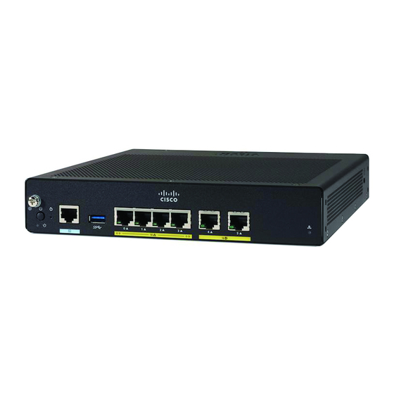
Cisco 900 Series Hardware Installation Manual
Integrated services router
Hide thumbs
1
2
Table Of Contents
3
4
5
6
7
8
9
10
11
12
13
14
15
16
17
18
19
20
21
22
23
24
25
26
27
28
29
30
31
32
33
34
35
36
37
38
page
of
38
Go
/
38
Contents
Table of Contents
Bookmarks
Table of Contents
Table of Contents
CHAPTER 1 Overview of Cisco 900 Series Integrated Services Routers
Chassis Views
LED Indicators
Power Supply
Specifications of Cisco 900 Series Integrated Services Routers
Periodic Inspection and Cleaning
CHAPTER 2 Prepare for Router Installation
Safety with Electricity
Prevent Electrostatic Discharge Damage
General Site Requirements
Site Selection Guidelines
Rack Requirements
Router Environmental Requirements
Power Guidelines and Requirements
Network Cabling Specifications
Console Port Connections
Eia/Tia-232
Console Port Considerations
Preparing for Network Connections
Ethernet Connections
Required Tools and Equipment for Installation
Chapter 3
Install and Connect the Router
Unpack the Router
Set up Router on Desktop, Rack, Shelf, or Wall
Rack Mount
Attach the Brackets to the Router
Mount the Router
Wall Mount
Mount the Router on Desk or Shelf
Mount the Router under a Desk or a Shelf
Chassis Grounding
Connect Power Cable
Connect the Router to a Console
Connect to the Serial Port with Microsoft Windows
Connect to the Console Port with Mac os X
Connect to the Console Port with Linux
Connect WAN and LAN Interfaces
Ports and Cabling
Connection Procedures and Precautions
Configure the Router at Startup
CHAPTER 4 ROM Monitor Overview and Basic Procedures
ROM Monitor Overview
Advertisement
Quick Links
1
Chassis Views
2
Led Indicators
3
Connect the Router to a Console
4
Connect Wan and Lan Interfaces
5
Configure the Router at Startup
Download this manual
Hardware Installation Guide for the Cisco 900 Series Integrated
Services Router
Last Modified: 2019-01-11
Americas Headquarters
Cisco Systems, Inc.
170 West Tasman Drive
San Jose, CA 95134-1706
USA
http://www.cisco.com
Tel: 408 526-4000
800 553-NETS (6387)
Fax: 408 527-0883
Table of
Contents
Previous
Page
Next
Page
1
2
3
4
5
Advertisement
Table of Contents
Need help?
Do you have a question about the 900 Series and is the answer not in the manual?
Ask a question
Questions and answers
Related Manuals for Cisco 900 Series
Network Router Cisco 901 Installation Manual
Aggregation services router (68 pages)
Network Router Cisco ASR 901 Command Reference Manual
Aggregation services router (218 pages)
Network Router Cisco Catalyst 9300 Series Hardware Installation Manual
(98 pages)
Network Router Cisco 910 Installation Manual
Industrial router (18 pages)
Network Router Cisco 910 Series Quick Start Manual
Industrial routers (24 pages)
Network Router Cisco ASR 9000 SIP-700 Hardware Installation Manual
Aggregation services router sip and spa (118 pages)
Network Router Cisco ASR 920-24SZ-IM Installing
(54 pages)
Network Router Cisco ASR 901 10G Series Hardware Installation Manual
Aggregation services router (82 pages)
Network Router Cisco Cisco 7000 and Cisco 7507 Chassis CHAS-7507 Replacement Instructions Manual
Cisco systems cisco 7000 and cisco 7507 chassis replacement instructions (48 pages)
Network Router Cisco Cisco 7000 and Cisco 7507 LED Board MAS-7KLED Replacement Instructions Manual
Cisco systems cisco 7000 and cisco 7507 led board replacement instructions (21 pages)
Network Router Cisco Catalyst 3560-X Software Configuration Manual
(1538 pages)
Network Router Cisco ASR 920 Series Configuration
Aggregation services router (52 pages)
Network Router Cisco 7604 Configuration Manual
Catalyst 6500 series switch and cisco 7600 series router firewall services module configuration guide using the cli (742 pages)
Network Router Cisco ASR 9000 Series Reference Manual
Aggregation services router vpn and ethernet services command reference (696 pages)
Network Router Cisco Catalyst 3550 series Software Configuration Manual
Multilayer switch (993 pages)
Network Router Cisco CSS11501S-C-K9 Configuration Manual
Secure content accelerator (462 pages)
This manual is also suitable for:
C921-4p
C931-4p
C921j-4p
Table of Contents
Save PDF
Print
Rename the bookmark
Delete bookmark?
Delete from my manuals?
Login
Sign In
OR
Sign in with Facebook
Sign in with Google
Upload manual
Upload from disk
Upload from URL


Need help?
Do you have a question about the 900 Series and is the answer not in the manual?
Questions and answers