Table of Contents
Advertisement
Seaim _nvlcisa
"_alning and Edu_etion
I
Electric
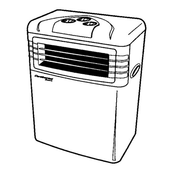
Included in this manual is all available information
covering
the Continental
portable air conditioners.
Models are being
sold outside the U.S. as well as inside the U.S. Although the
units may have different model numbers, both the customer
and service information are the same.
Listed below are the
European model numbers and the corresponding
U.S. model
numbers:
European
Model #
U.S. Model #
PAC-800
CE71096
PAC-88
CE72096
PAC-88E
CE73096
WA-9000
CE75096
WA-9000E
CE76096
WA-9000ER
CE77096
WA-12000
CE75126
WA-12000E
CE76126
WA-12000ER
CE77126
Sears Services
Training and Education
© 2000 Sears,
Roebuck
and Co.
Advertisement
Table of Contents

Related Manuals for Continental Electric PAC-800

Summary of Contents for Continental Electric PAC-800
- Page 1 Listed below are the European model numbers and the corresponding U.S. model numbers: European Model # U.S. Model # PAC-800 CE71096 PAC-88 CE72096 PAC-88E CE73096 WA-9000 CE75096 WA-9000E...
- Page 2 Electric Portable Air Conditioner Climatiseur Portatif Aire Acondicionado Portatil --""-_ CE71096 CE72096 CE73096 INSTRUCTION MANUAL GUIDE DE L'UTILISATEUR MANUAL DE INSTRUCCIONES Model/Modelo: CE71096 CE72096 Mechanical CE73096 Electronic...
- Page 3 DESCRIPTION OF COMPONENTS TIMING BUTTON FRONT SPEED SWITCH TEMPERATURE REGULATING SWITCH _HANDLE AIR OUTLET -- FRONT PANEL FOUR-WAY TURNING WHEEL REAR FILTER CLOTH INLET JL-..-]I _POWER WIRE COLLECTING CASE _Y-----1,_i HOSE WATER DRAINING _-._K /'(DRAIN PIPE) _I--7-HEATEXHAUST H OSE CONTROL PANEL TIMER SPEED...
- Page 4 Description of Contro! panel Model/Modelo: CE73096 Teml_rature tndicatm TIME TEMP Imllcato¢ COOLING IndOor • • _Button power MOOE POWER ON/OFF GDGD T_:_-'_u.m Button Trier Button...
- Page 5 MODEL/MODELO: CE73096 Mode Indicator When any of the indicators illuminates, it means the air conditioner is in the indicated function mode, Speed Indicator When any of theindicatorsilluminates, it meansthe airconditionerruns under the indicated speed _ow speed, mid speed, high speed). Timer Indicator If Timer Indicator...
- Page 6 DESCRIPTION OF OPERATION A.Connect exhaust hose to the back of the unit. Extend hose to desired length and connect with win- dow kit. USING EXHAUST DUCT Air outlet nozzle Exhaust hose EXhaust duct "A n Assembly & Installation: EXhaust duct "A" l.Insert ends of Exhaust hose into air outlet nozzle...
- Page 7 As:.:e.,_tLl-_ty & in_lati_li_a _3_' _anel: l.Fix Nozzle fitting , :'_ to Plastic panel by four screws 2.Install the panel in the window and adjust length of the panel by lengthening or shortening. |lol 3.Slide Exhaust hose into Nozzle fitting until it locks.
- Page 8 B.When the timer is turned to the "ON" position. will be in continuous operation. When the timer turned to 8. It will be continuously operated hours then shut down. freely adjust to your prefered time period according to your needs. C.The selection of the cooling air speeds:...
- Page 9 NOTES IN OPERATION 1. You should wait minutes before starting unit to assure that the coolant can flow back the compressor. 2. Please wait 3 minutes before restarting the unit after a normal shutdown so as to prolong the com- (Fig.A) pressor's life.
- Page 10 Exploded view...
-
Page 11: Table Of Contents
Parts List - PAC - 800 (CE71096) PARTS REMARK MATERIAL Quantity CODE FRONT PANEL A4200-020 A4237-030 DISCHARGE GRILLE (COMPLETE) VAN-AIR DEFLECTOR A4242-020 VAN-AIR DEFLECTOR A4242-030 VAN-AIR DEFLECTOR A4242-040 A4250-010 VAN-AIR DEFLECTOR A4242-050 VAN-AIR DEFLECTOR A4242-060 A4250-020 SIDE PLATE A4210-040 SIDE PLATE A4210-050 TOP COVER PLATE... - Page 12 FIXTURE A5811-090 FIXTURE A5811-100 FIX METAL A5806-100 STRIKE A5802-220 CONNECTING SLEEVE A5813-010 PADDLE SHAFT A7308-010 IRON SCREEN A7204-010 IRON SCREEN A7204-020 POWER SUPPLY CORD A3700-030 COMPLETE COMPRESSOR ASS'Y A3200-010 A3200-020 A3200-030 A3200-040 A3200-060 A3200-070 A3200-080 RUBBER A5600-020 VIBRATION PROOF SLEEVE A3208-010 SOUND ARRESTER...
- Page 13 TERMINAL BLOCK A2525-040 TERMINAL BLOCK A2525-050 FOAM U10AF270-355 73 i FOAM D3AF60-200 FOAM UIOAF3S-365 FAN CASING A5300-070 FAN CASING A5300-080 77 ! DRAIN PIPE IN UNIT VI.SP12-360 DRAIN PIPE OUT UNIT V2.5P10-160 79 I SOFT CAP A7307-010 FOAM E3AF115-300 VIBRATION PROOF RUBBER A5601-020 CAPILLARY...
- Page 14 Continental _ec_r'ic Portable Air Conditioner Climatiseur Portatif Aire Acondicionado Portatil INSTRUCTION MANUAL GUIDE DE L'UTILISATEUR MANUAL DE INSTRUCCIONES Model/Modble/Modelo: CE77126/CE75096/CE76096/CE77096...
- Page 15 Improper handling can cause serious damage to the appliance. Read this manual carefully before operating the unit. Do not allow chUdren to play with Do not let the unit run with Oo not wet the housing or the controls or drop any objects the air outlet flap closed.
-
Page 16: Front Panel
When first operating the unit a small amount of moisture may be generated lrom the unit which is the result of condensation left from factory testing. All units are factory tesled before leaving. Transparent cover to the control panel Air outlet Handle hole Front panel Flexible umbilical cord... - Page 17 Mounting brackets(with screws) ._--. 2 _=__ Screen filter ,Spanner ........tl _ O.,_r _i,'s Wall plugs(with screws) ...."---- "=-- Support _hook ....Frame ,or b,e connecting hose "_,_ _" kO:npe_toOerAon.ays Protective cap for connector(M) ..(F)..2/ _IB (ll Power cord compartment Handle Model/Modelo:...
- Page 18 DESCRIPTION Tr_$_r_t COVW to the ¢entto_ panel Car e!w',g Hande FtQnlplnl_-- Air intake exhaust hose connector ....exhaust hose ........ wan fit_ exhaust hose connector ..or ceiling Air intake Cover ol wai_fitting exhaust hose (Condenser) connector ........Power cord Water draina_;e pipe and pipe plug...
- Page 19 Description of control panel Safety warnin 0 light Fan speed control dial Timer control dial Temperature control dial • During operation yoU_may hear the compressor stop,(the fan will continue working) this is because the temperature has been reached on the temperature control dial.
- Page 20 Fan operation only speed control dial. Timer setting dial. t or 2 or 3 speed control Setting from 1 to 8 hours or continuous operation CONT THERMOSTAT COOLING TIMER Air-conditioning Temperature control dial. Timer setting dial For setting your temperature requirement Setting from 1 to 8 hours...
- Page 21 Control Panel Model/Modelo: CE76096 Only [_]o ,_ [_oe @@®©@@ 12 "On/OfF key 13 Alarm light: comes on when the condensatecollecting tank isfull. 14 "Function" key: (or selectingthe operating mode: ventilation only or air conditioning: the light (a) or (b) comes on depending on the mode chosen.
- Page 22 • Periodic cleaning and maintenance may maximize the air condition'sfunctions and optimal condition. • Prior to cleaning and maintenance, please make sure to temove the plug from power socket to ensure safety. Maintenance for the Filter cleaning Check once a week outdoor unit •...
- Page 23 • Pedodls cleaning, maintenance and proper use may not only maximize the air conditioner's functions, but also can avoid increasing unnecessary expense. Take note of the following Clean filter periodically points • When using it in normal conditions, please clean the filter at least once •...
- Page 24 • This procedure should be carried out by a professional person to avoid expensive mistakes. 6.Use the 2 spanners provided Steps in disassembly disconnect the 2 pipes, t,Turn off the air conditioner,and remove the plug from the power sucket Make sure the tubes and connectors are kept level while disconnecting to avoid coolant leaking.
- Page 25 IMPORTANT: Do not have any sharp hands or twisting it the umbilicalcord. For permancnt installation follow instructlens. If you are not sure contact a service company. Indoor Unit • METHOD The umbilical cord can pass through partly open door or window. The location of the indoor unit must have at lease 10cm space at the rear and away from curtains/drapes.
- Page 26 Installation of heat exhaust hose Model/Modelo: CE75096, CE76096, CE77096 USING EXHAUST DUCT 1.Connect one heat exhaust hose connector anti-clockwise to the heat exhaust hose. 2.Connect the other heat exhaust hose anti-clockwise to the other end of heat exhaust hose then connect the connector to the appliance clockwise.
- Page 27 The Installation of window panel kit Model/Modelo: CE75096, CE76096, CE77096 ® Assembly & Installation Panel: 1.Fix Nozzle fittin ,_ to Plastic )anel .U_ with four screws _) 2.Install the panel in the window and adjust the length of the panel by lengthening shortening.
- Page 28 Warning Each time you bring the outdoor unit inside always turn the air eondilioneroff at the power supply If you do not and move the inside unit the debumidif'_l water in the container inside the unit could activate the water pump and discard water from the tube on the outdoor unit, The Outdoor Unit...
- Page 29 • A majority of malfunctions are small, and triggered by problems that can easily be resolved; before calling for service, please refer to the following table for sequential inspection. PROBLEM CAUSES RESOLUTIONS • Power failure • Wait for the power to come Air conditioner stops back on.
- Page 30 ®@®©@...
- Page 31 _f_l...
- Page 32 12 "On/Off" key 13 Alarm light:comesonwhenthecondensatecollectingtank is ElL 14 "Function" key:for selecting t he operating mode:ventilation only or air conditioning: the light (a) or (b) comes on dependingon themodechosen. 15 Ventilation speedselection key Light(c)on: slowventilation speed Light(d) an: mediumventilation speed Light(e) on: high ventilation speed 16 "Night operation"...
- Page 33 NEW WIDETECH PORTABLE AIR C ONDITIONER WA-9000 WA-9000E WA-9000ER • II /11...
- Page 34 SPECIFICATION Portable conditioner Dcs,:ript im+ of product \VA-9000 / WA-9OOOE ] WA-9000ER +_k; d e I 46cm*78cm*32cm Size uf _!_¢i1 (W+H*D) 13-19 Area , ,, ,,,,,,,,, ,,,,, ,,,, , ,,, 115/60 220-240t50 Voltage /Freguency 103.5- 126.5 207 -253 (Derating cycie(V) 9OO0 ( B.T.U., ('_01i_,_ c:,pa,i{y...
- Page 35 Description ofComponents I III Transparent cover control panel outlet .J" Frompa,.el ...
- Page 36 Screen filter upper co\el R_ar Heat exhaust .... Rear lower cove Power wi re Waterdrainage _ipe P pe plug...
- Page 37 \x,, A - 9000 Alarm Fan speed control dial {:au,_ s peed control dial i.arnp ," OI __" ) _" ">spr_*dcontra7...
- Page 38 WA-9000E WA-9OOOER Control panel ,_.. _lll l II -- Siec|_ }:im _-e¢i r-1 Tim_-r orJ_¢d I_im_! olfl _',:ce I_J _ o _. ,½. F_II _Ix%*d J l--- Nk.'_g:*...
- Page 39 w A-9000ER l:_,at_a:y co_:c.:_.BACK ) Remote ( ontr+_I "...
- Page 40 / Capillary Outdoor Radiator Drum OutdoorMotor Liquidaccumulator C0oli_ S _st_m O:._.ztim Dh_ram WA-9000 IRE-D) rIMER i FAN s_Tt'K T_ERMOsTAT ,o'_=-_ IL.LI ...._.I_,._,_ _qi¢-" i ''_ill_ _LUE) l'SuF145_'ti ._.___. - .._B.L. UE) (._LU_ 25uF/370Vi {BLUE} I (BLUE}_ Schematic Wi6n_ Diagrams...
- Page 41 Schematic W iring Diagrams ,,,,, WA-9OOOE (ZO_T ROL F_)_RD ]l [('R{I TEIP S'ITC'I N'%E_SOR p1 _£2.a r...a1,...,= _ (RED) i_" ... ._ ..BOhRD • 22 oONZz 4Ova" (WHITE) _--- m=! i _ _i ,. +_ ..t=- _i:_ (BLUE) 'IuF/45OV 250FI3"IOVi(BLUE_l.SuFt450 _ BLUE) Schematic W iring Diagrams...
- Page 42 THE R EASON OF BREAK DOWN AND T HE W AY TO SOLVE PROBLEM WAYS TO SOLVE IT. POSSIBLE REASONS OPower failure. QWait for the electri_,ity. Air conditioner ,[',Plug on. ()Did not plug on. working OSet the timer switch to the proper ODid not set the timer.
- Page 43 COOLING SYSTEM FLO k CHART, AIR CONDITIONER] POWER FAILURE NOT WORKING TIMER OUTOF ORDER AND FUSEWIRE NOT COOL CHECK THEMAINS_'ITCHH AIRSPEED SWITCH A DJUST] I L0WER TE_IPERATURE SETUP t TOAIRCONDIT1DNING I PROTECTOR B REAK DOWN LOMPREbS{ R NOT WORKING CAPACITOR BREAKDOWN LEAKAGE OF COOLANT ] SYSTEM REPAIR USE DISCHARGE TO FILL...
- Page 44 WA-9000 E XPLODE DIAGRAM ACCESSOR...
-
Page 45: Discharge Grille (Complete)
WA-9000 AIR CONDITIONER PARTS LIST (CE75096) REMARK SPECIFICATION MATERIAL ENGLISH NAME QUANTITY NO. I TURING WHEEL D=45mm M6 A7402-010 SPCC T=1.4mm A4800-010 BASE PAN Coating 220-240V/50Hz A3200-010 COMPRESSOR ASS'Y NBR65% A5600-010 RUBBER A6100-010 A5811-030 FIX TURE A4237-020 DISCHARGE GRILLE(COMPLETE) A5811-050 FIX TURE ' _APILLARY TUBE... -
Page 46: Side Plate
A4200-010 FRONT PANEL A4233-020 KNOB A4237-010 DISCHARGE GRILLE(COMPLETE) A4242-010 VAN-AIR DEFLECTOR A5303-010 BLOWER WHEEL ABS D=200mm A5300-030 FAN CASING A5300-040 FAN CASING A3000-030 FAN MOTOR 220V/50Hz A5802-030 STRIKE SGCC T=1.2mm A5802-040 STRIKE SGCC T=1.2mm A2509-020 CAPACITOR A2509-010 CAPACITOR A2525-010 TERMINAL BLOCK HP-T4009-2 A2525-020... - Page 47 WA-9000E WA-9000ER EXPLODE D IAGRAM WA-9000ER ACCESSOR...
- Page 48 WA-9000E(WA-9000ER) AIR CONDITIONER PARTS LIST (CE76096-CE77096) MATERIAL ENGLISH NAME SPECIFICATION REMARK A7402-010 TURING WHEEL D=45mm M6 A4800-010 BASE PAN SPCC T=1.4mm Coating A3200-0|0 COMPRESSOR ASS'Y A5600-010 RUBBER NBR65% A6100-010 A5811-030 FIX TURE A4237-020 DISCHARGE GRILLE(COMPLETE) A5811-050 FIX TURE A6204-010 CAPILLARY TUBE A6208-010 DISCHARGE...
- Page 49 A5303-020 BLOWER WHEEL A3000-040 FAN MOTOR 220V/50Hz A2509-030 CAPACITOR STRIKE SGCC T=1.2mm A5802-070 STRIKE SGCC T=1.2mm A5802-080 A4200-010 FRONT PANEL A6100-020 A4237-0 t 0 DISCHARGE GRILLE(COMPLETE) A4242-010 VAN-AIR DEFLECTOR A5303-010 BLOWER WHEEL ABS D=200mm FAN CASING A5300-030 A5300-040 FAN CASING A3000-030 FAN MOTOR 220V/50Hz...
- Page 50 NEW WIDETECH SPLIT PORTABLE AIR C ONDITIONER WA-12000 WA-12000E WA-12000ER SERVICE MANUAL...
- Page 51 SPECIFICATION Spl i t Por'i able Cond_ t loner De,trip!ion of producl WA- 12000 / \\A- l 2OOOE 1 \\A- 1200OER [,IOd e I Size of shell ( g-*lt*D ,a6 qcra,.Slcm_-31.-mllndimr U[Iil )£5,'Itl*4fi_'lll"ll}¢lli(IR kt:lIt] 19_-25 Area (Ill:) 220_-240150 \oltage /Freg,uency 207_253 Operating cyc:e(...
- Page 52 Description ofComponents control panel Transparent cover Top covei Air outlet Handle hole Side plate Front p anel Castor...
- Page 53 Screen filter Rear upper cover Outdoor unit's mounting screw to umbilical connection. Always keep cover Flexible umbilical cord Rear cover down Handle Power cord compartment Water drainage pipe pipe plug Cabinet Base pan _,_y ¸.¸.4 _'J_ Wall plugs_,with _crews) flexible "-_.
- Page 54 WA- 12000 Alarm Fan speed control dial Temperature Timercontrol cortrol dial \ dial Fan speed control dial ' O1 or2 or3 slk-"_d cor|trol (.-,, • Temperature control dial/ ' Timer control dial OFor selting your temperature OSctling from 1-_, hour_ or conlmuous operation requirt'men! or con t inuou...,cooling...
- Page 55 WA-12000E WA-12000ER Control panel...
- Page 56 WA-12000ER ÷ Power switch Adjust OAdj ust tempe rature Io • .su tabt¢cond t]on(16-J Battary cover(BACK) OU_e two No.4 batteries Remote Control...
- Page 57 System Operating & Schematic wiring Cooling Diagrams [Mo'orJ {E+,,_or,,,o,. ' /+ +i:++ i F-- i " ;-q [agu,d ac£umut!_t,.Li Coolin+. System O t+eratin_ Diagram WA-12000 TIMER RE[)+FL'tS|IT('!I +RED+ TfiE+t -+---+.:.;+.,c,c.,+ + _,,,--, ic+ c+-- .... tRI-D+ BRII_',NI _bRi;WP,h tOR '_bk;EJ +H_ {YELtOWl _ 't Eli.O's\% Ix++R P UWI' (")
- Page 58 Schematic Wiring D iagrams WA-12000E i (RED) 50Hz i (BLUE) 1,5UFI4 50V (BLUE) SchematicWirin_o DiLorams WA-12000ER r...--.._ C:::lC::3 r..-1 _,=i=_l___J i r = pOllER = ie "-- (BLUE) 1,5uFI4S0V 25uFI400Vi 3.5UFI400V (BLUE) Schematic Wirin_ Diagrams...
- Page 59 •HE R .ASON O: B REAK DO IN AND THEIIAk TO _OLkEh. _ 'T PROBLEM BLE REASONS POSSI \','AYS TO SOLVE [T. cond]t_or.cr • Pov, cr fail ure. _\\'ai: for th_ _k'clrici::,. i)id nor plug on, 'ao r k I h ,2 P:L:gOll.
- Page 60 COOLING SYSTEM FLOW C HART, AIR CONDITIONER NOT WORKING POWER FAILURE TII_IEROUTOF ORDER NOT COOL AND FUSEERE CHEt'K THE MAINS_'IT(.'HH LO_'ER T EMPERATURE SETUP [._lR SPEED SIITCH A DJUST] TOAIRCOHDITIDRIIIGI PROTECTOR B REAK DOWN CAPACITORBREAK DOWN COUPRESSOR NOTfORKING I LEAKAGE OF COOLANTI SYSTEM REPAIR USE DISCHARGE TO FILL N:lSkg/cm...
- Page 61 WA-12000(WA-12000E WA-12000ER) EXPLODE DIAGRAM(IN DOOR U NIT ACCESSOR ,.--, ._:_ WA-12000 WA-12000E...
- Page 62 WA-12000 (WA-12000E WA-12000ER) EXPLODE DIAGRAM(OUT DOOR U NIT) ®...
-
Page 63: Top Cover Plate
WA-12000 (CE75126), WA-12000E (CE76126), WA-12000ER (CE77126) SPLIT PORTABLE AIR CONDITIONER PARTS LIST MATERIAL PARTS NAME SPECIFICATION Q'IY REMARK CODE A4205-010 TOP COVER PLATE l° A4215-010 TRANSPARENT ABS, TRANSPARENT A4253-010 CONIROL PLATE WA-12000E _4233-010 KNOB A42334)20 KNOB A4233-030 KNOB A4200-010 FRONr PANEL A4237-010 DISCARGE GRILLE... -
Page 64: Gasket
GASKET SGCC ,T=1.2ram 45. A3204-080 46 A5806-060 FIX METAL SGCC ,T=1.2ram 47. A5806-070 FIX METAL SGCC ,T=1.2ram 48. A5806-080 FIX METAL SGCC ,T=l.2mm 49. A5806-090 FIX METAL SGCC ,T=l.2mm 50. A3200-050 COMPRESSOR ASS'Y 220-240V 50Hz 51. A2509-030 CAPACIIOR 220-240V 50Hz 52. - Page 65 A6101_10 PVC60% SCREW "lOP COVt_ A5802-140 STRIKE A5811-020 FIX TURE A4242-010 VAN AIR DEFLECTOR A5802-090 STRIKE SGCC,T=1.2mm A6100-050 SWT4 SCREW CLIP D=4mm A7202-010 HANG BOLT M5"35 WA-12000E A680_020 NAME PANEL P.P, T=0.5mm A7409-010 SCREW PLASTIC 4*40 BELT A7304-010 BELT A7302-010 SPANNER T=3mm,SPCC 100.
- Page 66 ELIMINATE ACCIDENTS toW r fdy.'...
Need help?
Do you have a question about the PAC-800 and is the answer not in the manual?
Questions and answers
pac-88 makw=es a loud noise when the water tank is full, but no water is discharged out of the drain pipe - is the pump jammed? - if so - how to free it or replace it (and where to obtain a replacement pump...) - at the moment, i am having to manually mop the contends of the water tank with a sponge when it filled up, The relay switch operates - but just makes a very unhealy=thy sounding loud, electrical buzzing