Table of Contents
Advertisement
Advertisement
Table of Contents

Related Manuals for Fujitsu SRS-9924

Summary of Contents for Fujitsu SRS-9924
- Page 2 USER GUIDE SRS-9924/9912-SP Fujitsu NI / 5E Custom Terminal Intro & Table of Contents NI / 5E Custom Terminal Overview Terminal Set-Up NI / 5E Custom Terminal Installation Terminal Accessories NI / 5E Custom Terminal Testing NI / 5E Custom...
- Page 3 Printed in the United States of America. This publication may be replaced by a revised edition. To find out if a revision exists, or to order copies of publications, write to Fujitsu Network Communications, Inc., 2800 Sumner Blvd., Suite 124, Raleigh, NC 27616, or call 1-800-228-ISDN.
- Page 4 Warning This equipment has been tested and found to comply with the limits for a Class B digital device, pursuant to Part 15 of the FCC rules. These limits are designed to provide reasonable protection against harmful interference in a residential installation.
-
Page 5: Using The
If this occurs, you will be notified in advance in order to make necessary modifications to maintain uninterrupted service. Important Safety Information The Fujitsu ISDN Terminal should be used according with all instructions and precautions provided in this guide. •... -
Page 6: How To Use This Guide
ISDN (National ISDN, referred to as NI or 5E Custom versions). For assistance ordering National ISDN service from your local service provider, see Appendix C. The Fujitsu SRS-9924 and SRS-9912-SP are designed to optimize Centrex and other ISDN voice services. HOW TO USE THIS GUIDE This section can help you make the most efficient use of this guide. - Page 7 Conventions and Layout • In procedures, the required actions are noted, with the buttons you press in capital letters, such as HOLD or REDIAL. • Other important words, such as messages that appear on the display, also appear in CAPITAL LETTERS. •...
- Page 8 Softkeys The softkeys are the four keys located just below the display. 12:05PM L-DIR Standard Softkey Layout ENTER NEXT Other Softkey Functions (For entering information as indicated in this User’ s Guide.) You can display the labels at any time without affecting the tasks you are performing.
- Page 9 Dialing 9. When you dial for an outside line (usually by pressing 9), you do not hear a pause and a second dial tone. You can begin dialing the telephone number immediately. Onhook dialing. You can dial a number before you get a dial tone. The number you dial appears on the display and remains there for three minutes.
- Page 10 • They allow the incoming directory number and calling name to be displayed if it is available from your service provider. Multipoint Configurations In multipoint configurations, ISDN lines are shared by two or more terminals. Usually, two terminals will share a BRI, allowing one B-channel for each terminal.
-
Page 11: Table Of Contents
MULTIFUNCTION BUTTONS ... 1-8 CALL INFORMATION DISPLAYS ... 1-9 SOFTKEYS AND MENU ... 1-10 Chapter 2 USING THE FUJITSU TERMINAL ... 2-1 PLACING AND RECEIVING CALLS ... 2-2 Handset Calls ... 2-3 Handsfree Calls ... 2-3 Headset Calls ... 2-4 PLACING A CALL TO A LEASED NETWORK (5E CUSTOM) ... - Page 12 Specifying the Directory Numbers of Call Screeners ... 3-21 CALL APPEARANCE PREFERENCE ... 3-23 MIC-OFF ... 3-25 SETTING UP/EDITING THE PERSONAL DIRECTORY ... 3-26 Chapter 4 SRS-9924-ADD-ON BUTTON MODULE ... 4-1 Chapter 5 INSTALLATION ... 5-1 INSTALLING THE TERMINAL ... 5-2 CONNECTING TO THE NETWORK ... 5-3 SETTING-UP SPIDS ...
-
Page 13: Getting Acquainted With Your Digital Set
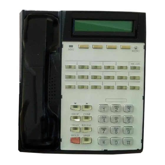
S R S - 9 9 2 4 DROP CONF TRAN REDIAL HOLD SPKR Volume/Contrast Buttons Figure 1-1: SRS-9924 National ISDN - Front Panel Multifunction Buttons SRS-9924-ABM MENU M I C - O F F A B C D E F J K L... -
Page 14: Function Keys
Volume/Contrast Buttons Figure 1-2: SRS-9924 5E Custom - Front Panel Softkeys M S G MENU M I C - O F F S R S - 9 9 2 4 A B C D E F DROP CONF J K L... - Page 15 M S G SPKR Volume/Contrast Buttons Figure 1-3: SRS-9912-SP National ISDN Front View Display M E N U Softkeys M I C - O F F Multifunction Buttons A B C J K L G H I M N O Numeric Keypad P Q R S...
- Page 16 Figure 1-4: SRS-9912-SP 5E Custom National ISDN Front View M S G A B C DROP CONF J K L G H I M N O TRAN REDIAL P Q R S T U V W X Y Z HOLD SPKR Volume/Contrast Function Keys...
- Page 17 LINE OFF ON Terminating resistor ISDN Line Connector Figure 1-5: Digital Set Rear View Figure 1-6: Digital Set Bottom View 48V DC OFF ON DC power connector Handset/Headset Power Source selection connector located beneath terminal Handset /Headset plug Rear stand...
-
Page 18: Unique Components
Unique Components Switches and Connectors LED Indicators Softkeys/MENU. Four buttons below the display with changeable functions. The MENU key displays the current functions on line 2 of the display. Multifunction buttons. These buttons are assigned to CAs, DNs, one-touch numbers, or network features. -
Page 19: Mic-Off Button
TRANSFER: (with LED indicator) Transfers a call to a third party you dial or select (Button 20) HOLD SPKR NI utilizes Feature Activators 20 or 61 Figure 1-7: Button assignments are identical between the Function Button SRS-9924 and the SRS-9912-SP . Layout Holds an active call... -
Page 20: Multifunction Buttons
MULTIFUNCTION BUTTONS Multiple Directory Number Appearances Call Handling Example with Multifunction Buttons Multifunction buttons have three uses: One-touch: Dial a stored number. Network Feature: Activate or deactivate a special network feature, such as call forwarding. Call Appearance (CA) or Directory Number (DN): Handles incoming or outgoing calls. -
Page 21: Call Information Displays
DN. Figure 1-8: Example Line Assignment - SRS-9924 If your DN is 747-3456, and the first three multifunction buttons on your digital set have been assigned that number, you can have up to three calls at the same time using that single DN, though you can talk on only one at a time. -
Page 22: Softkeys And Menu
NI ONLY 5E CUSTOM ONLY SOFTKEYS AND MENU 1-10 For an incoming call, the calling party’ s number appears if the network supplies the digital set with the Calling Line ID (CLID). When your party answers, the call duration timing is shown as minutes and seconds. -
Page 23: Using The Fujitsu Terminal
SPKR connects you to an idle line (if there is one). You can then make an outgoing call or press a green-flashing Call Appearance button to pick up an incoming call. USING THE FUJITSU TERMINAL CHAPTER 2... -
Page 24: Placing And Receiving Calls
CA, you must either press SPKR for handsfree operation or lift the handset. The SRS-9924 and SRS-9912-SP are equipped with a speaker and microphone built-in to utilize handsfree operation. In order to place and receive... -
Page 25: Handset Calls
Placing 1. Pick up the handset. This should automatically give you a dial tone. If not, press the idle Call Handset Calls Appearance (CA) you wish to use. 2. Dial the desired number. 3. Converse with the called party, then hang up. 1. -
Page 26: Headset Calls
Receiving Handsfree Calls Placing Headset Calls Receiving Headset Calls 1. Press SPKR and, if necessary, the green-flashing CA button. 2. Converse with the calling party. 3. Hang up by pressing SPKR. Check that headset mode is activated on your telephone. The handset, speaker, and microphone will be disabled. -
Page 27: Placing A Call To A Leased Network (5E Custom)
1. Press SPKR and then replace the handset in its Switching cradle. You now hear the other parties on the between Handset call through the speaker. and Handsfree Modes 2. If the MIC-OFF LED is red, the microphone has been turned off. Press MIC-OFF to turn it back If you are using the on (the LED goes dark). -
Page 28: Function Buttons
(REDIAL, HOLD, and SPKR) and the other three buttons are usually assigned to CONFerence, DROP and TRANsfer. On NI, Fujitsu supports two sets of telephone company assignments for network based features. On the labeled function buttons for CONF , DROP,... -
Page 29: Redial
5E Custom These assignments are not used for 5E Custom ISDN. ONLY REDIAL If there are no idle CA’ s available, pressing REDIAL Dials the last brings the number to the screen but does not dial. number dialed When an idle CA later becomes available, pressing on this phone the CA button dials the number. -
Page 30: Drop
Dropping Out of the Conference Call DROP • If the person answers, you can talk privately before joining the conference. • If the line is busy or the person does not answer, press DROP . Then press the flashing CA button to return to the initial call. •... -
Page 31: Transfer
You can use the DROP button repeatedly until you have dropped everyone but the participant of the original two-party call. To end the call, hang up normally. Warning: Pressing DROP at the end of a TRANSFER Transfer is a network-based feature that you must <5E Custom, 5E NI, subscribe to from your telephone company. - Page 32 TRANSFER <DMS-100, NI1> Transfers a call to another phone TRANSFER <EWSD> Transfers a call to another phone 2-10 To transfer a call, follow these steps: 1. While still on the call, press CONF. The CONF button indicator lights up. The call is put on hold and its CA indicator flashes red.
-
Page 33: One-Touch Calling
3. The procedure also assumes that both the screener and the call recipient have a Fujitsu digital set, although only the recipient must have one. If the call screener has some other telephone set, the exact procedure may be different. - Page 34 2-12 This procedure is by no means the only way that you can use Call Announce Intercom. To announce a call by intercom, follow these steps: 1. Press the DN designated for Call Announce Intercom. The intercom DN indicator lights normally.
-
Page 35: Unanswered Call Logging (Una)
UNANSWERED The UNA feature records information from the eight most recent unanswered calls, showing the date, CALL LOGGING the time, and the telephone number and name (if (UNA) provided) of the calling party. The ninth and later unanswered calls replace the first, second, and so If enabled, this forth, in order, so that your UNA list always has the feature records... -
Page 36: Personal Directory
1. Press L-DIR to access the directory. L-DIR >01=BILL HALEY 02=FUJITSU 2. Scroll to the name of the person you want to call, or enter the Directory Address (01, 02, etc.) for that person. Press the # key to scroll forward and * to scroll back. -
Page 37: Chapter 3 Terminal Set-Up
MENU MODE The terminal has a menu from which you select OPERATIONS options to change local features. Note: Setting up the SPID (option 8) is described in Chapter 5. The procedures to set local features require the use of the softkeys located below the display. To see the names of the softkeys, press MENU. - Page 38 Selecting a Menu Option NI ONLY 5E CUSTOM ONLY NI ONLY 5E CUSTOM ONLY You can display and choose among the menu options at any time, as follows: OPTIONS NEXT NEXT NEXT NEXT NEXT Press NEXT repeatedly to cycle through the menus. 2.
-
Page 39: Programminga Button For One-Touch Dialing
Notes: If you enter menu mode during a call, special features such as Call Pickup and Call Forwarding are temporarily disabled. However, regular calling controls such as HOLD, SPKR, MIC-OFF, and call disconnection remain available. Once you are familiar with the menu choice numbers, you can go directly to the one you want after pressing OPTIONS. - Page 40 NI ONLY 5E CUSTOM ONLY The indicators for previously assigned one-touch buttons will be green. The indicators for buttons assigned to Directory Numbers (DNs), Call Appearances (CAs), and features will be red. You cannot program the buttons with red indicators for one-touch dialing. In One-Touch mode, Call Appearances CAs, Directory Numbers DNs and Feature buttons are unlit.
- Page 41 Notes: If you enter a number with more than 16 digits, the 17th and subsequent digits appear in the 16th number position, and previously entered digits are shifted one column to the left. (The digit in the first number position disappears from the display, but is still recorded.) If you try to exceed the 30-digit limit, the set refuses the input and the display remains...
- Page 42 Including Codes in a One-touch Number Changing or Canceling the Number Stored in a One-Touch Button You can code both telephone numbers and one or more special code numbers on a single one-touch button, with appropriate pauses between numbers to allow for system response. You can code up to 30 digits, with each pause character counting as one digit.
- Page 43 2. Press the one-touch button whose number you wish to change or cancel. The ENTER DIRECTORY NUMBER screen appears showing the currently assigned number: If the number stored on the one-touch button is more than 16 digits, a right arrow ( ) appears at the end of the line of numbers, indicating that additional numbers exist.
-
Page 44: Setting The Calendar/Clock
SETTING THE CALENDAR /CLOCK The normal display includes the date, time, and day of the week. To set the calendar/clock, follow these steps: OPTIONS ENTER 3. Enter the present hour and then press ENTER. The screen changes to reflect your entry and to prompt for the minute. -
Page 45: Reinitializing The Phone
6. To accept the year displayed, ’99, press ENTER. Or To change the year, press two numbers for the year you want and then press ENTER. The screen changes to reflect your entry and to prompt for the month. In this example, assume you accepted the displayed year. -
Page 46: Unanswered Call Logging (Una)
UNANSWERED CALL LOGGING (UNA) If enabled, this feature records information about incoming calls that were not answered at this phone. Enabling the UNA Feature 3-10 OPTIONS Press 1, then ENTER to clear all data, Or Press 2, then ENTER to retain all data. If you choose 1, this screen appears: To return to normal operation, press OPTIONS. - Page 47 2. To enable UNA, press ENTER. This screen appears: Note: If the following screen appears, press ENTER to go to the selection screen. To support UNA on all CAs, follow these steps: UNA on All Call Appearances After about 6 seconds, or if you press asterisk (*), the display returns to the second menu mode screen: 2.
- Page 48 Disabling the UNA Feature 3-12 2. Press ENTER when done, and this screen appears: After about 6 seconds, or if you press asterisk (*), the display returns to the second menu mode screen: 3. You can now select a different menu function, or press OPTIONS to return to the normal display.
-
Page 49: Enabling/Disabling The Speaker Function
4. You can then select a different menu function, or press OPTIONS to return to the normal display. This feature enables and disables the speakerphone ENABLING AND function. DISABLING THE SPEAKER FUNCTION ENTER 3. Press 1 or 2 to select your choice. 4. -
Page 50: Changing Ringer Mode
Handsfree Non Supported Using the Handset or a Headset CHANGING RINGER MODE Setting Ringer Volume 3-14 Disallows speaker use. The SPKR button is disabled. Call pickup and hanging up on calls is by handset only. OPTIONS 2. Press ENTER, and this screen appears: 3. - Page 51 ENTER ENTER 5. Press the desired volume number. The phone rings once at the selected volume. 6. When you hear a volume you like, press ENTER. To change another setting, you can press asterisk (*) to return to the menu mode options. Setting Ringer To set the ringer tone, enter Ringer Service Mode Tone...
- Page 52 Selecting Ringer Pattern Selecting Ringer Pattern Mode 3-16 ENTER 3. Press the desired tone number. The phone rings once at the selected tone. 4. When you hear a tone you like, press ENTER. The following screen is shown: Select either normal ring or silent ring. Silent ring flashes the LED of the receiving DN or CA button without ringing the bell.
-
Page 53: Assigning A Leased Network Access Code Delimiter (5E Custom)
To select the ringer mode, enter Ringer Service Mode then choose option 4. ENTER 3. Press the desired option, then ENTER. The following screen is shown: Before you can dial a leased network number, or Assigning a program a one-touch button to dial such a number, Leased Network you must assign one of your multifunction button Access Code... -
Page 54: Call Announce Intercom
CALL ANNOUNCE INTERCOM 3-18 If you have previously assigned a button as the delimiter key, its indicator turns green when you complete step 2. You have two choices at this point: • If you press a different button and press ENTER, the indicator of the previously assigned button goes off and the indicator of the new button turns green. -
Page 55: Call Announce Intercom On Selected Buttons
Call Announce Intercom allows you to specify which call buttons are activated by Call Announce Intercom Call Screeners, and allows you to select up to three Call Screeners. Note: Call Announce Intercom is distinct from Network (Switch provided) intercom. Ringer Always The Call Announce feature utilizes a Ringer Always On mode. -
Page 56: Specifying The Directory Number For Intercom
Specifying the Directory Number for Intercom 3-20 ENTER Select from the following: 1: ALL: all call appearances will be lit green and will be activated to auto-answer. 2: SELECT: only CAs with lit LEDs will auto- answer on Call Announce. 3: NO SUPPORT: turns off all LEDs green lights, none of the call appearances on the recipient set will auto answer. - Page 57 At the conclusion of selecting buttons for Call Announce Intercom, this screen appears: 1. Press ENTER. If one or two way intercom is enabled, the screen displays the enabled mode plus the authorized DN, as shown below: If no telephone numbers have been programmed in, the Call Announce Intercom feature is disabled, and the screen displays NON SUPPORTED: To program the first number and enable Call...
- Page 58 3-22 4. Input the directory number of the call screener exactly as it appeared on the display of your set when you had the call screener call you. Example: 919 926-3112 or 9199263112 Press the asterisk * key for spaces (like the space between the first 9 and the second 9) and for dashes –...
-
Page 59: Call Appearance Preference
Repeat steps 2 and 3 until this screen appears: Note the number (2) on the first line indicating you are about to program your second call screener number. Pressing NEXT repeatedly at this prompt will cycle you through all three call screener selections to the one you want to program or change. - Page 60 Selecting CA Preference 3-24 • Ringing line preference. Selects the CA button that is ringing with an incoming call. If you have more than one incoming call, the terminal selects any ringing Intercom or Intercom Group feature button first, and then selects the button with the call that has been ringing the longest.
-
Page 61: Mic-Off
MIC-OFF If you deactivate MIC-OFF, assign the upper right button as a one-touch button, and then try to reactivate MIC-OFF, the button’ s LED turns red as a warning. You must quit the procedure (press * to return to the menu mode main menus) and cancel the one-touch number before you can reactivate MIC-OFF. -
Page 62: Setting Up/Editing The Personal Directory
SETTING UP AND EDITING THE PERSONAL DIRECTORY 3-26 1. Press L-DIR to access the directory. L-DIR 2. Press L-DIR repeatedly to either go to the directory entry to change, or to get to the next available number for a new entry, then press MENU. - Page 63 Letters Press the keypad numbers corresponding to the letters in the name. The first press of a keypad digit displays the first letter from the group of letters represented by that key, such as 2 for ABC, 3 for DEF , etc. The first letter of the group appears on the display.
- Page 64 USING NETWORK DATA IN THE PERSONAL DIRECTORY Key Label PQRS WXYZ 3-28 When you receive an incoming call, and the “Caller ID” or other caller information is displayed, you may use this as an entry in your Personal Directory. Note: If the directory is full, the message DIRECTORY FULL will be displayed.
- Page 65 One-Touch keys, many ISDN features, or who need access to multiple CAs. The ABM is connected to the SRS-9924 by a cable which plugs in beneath both units, as well as by a metal plate.
- Page 66 SRS 9924 ABM 5E Custom ABM button number Assignments Figure 4-2 SRS-9924-ABM...
- Page 67 ABM cable. 2. Place the ABM and the terminal side-by-side to position the connector plate. 3. Insert and tighten the four screws to connect the two units. Cable Connector Plate Figure 4-3: SRS-9924-ABM Bottom View...
- Page 68 Notes...
-
Page 69: Chapter 5 Installation
These instructions are intended mainly for System Administrators, service personnel or end users who are installing the terminal. Installation involves four main steps: Required Steps • Connecting the set to the network. It’ s necessary to determine the type of Telephone Company switching equipment in use for proper connection to the Telephone Company network. -
Page 70: Installing The Terminal
INSTALLING THE TERMINAL To Telco 2 Wire or 4 Wire ISDN equipment may be installed in a number of configurations. In most installations, the supplementary equipment (NT1 and power) is located in a wire closet in your building. If this is the case in your installation, please skip to the section “Connecting to the network”. -
Page 71: Connecting To The Network
To Telco RJ-11 RJ-49 8 Wire 2 Wire or 4 Wire Line Term Figure 5-2: Power Connections CONNECTING When you receive your terminal, plug the telephone TO THE line from the wall into the LINE jack on the back of the set. - Page 72 Auto-SPID Manual SPID Entry (For 5E Custom and for If your switch supports Auto SPID, this function starts when either the terminal is powered-on and a SPID is not present, or when the SPID has been manually cleared. Auto-SPID displays the following screens: AUTO SPID REQUESTING If only one SPID available, the SPID is assigned, and this screen is displayed:...
- Page 73 ENTER SPID ID=000000000000 2. Dial your voice SPID number and press ENTER. SPID ASSIGNMENT END COMPLETED Note: For first time installations, download will occur without plugging and unplugging the set. At initial installation, when you press ENTER to confirm the SPID, the terminal automatically requests a download from the switch.
- Page 74 configuration types (CACH or EKTS) and the instructions on how to change the terminal settings for proper operation. If your service provider has not supplied a SPID to you, try this format shown above. If it does not work, contact your service provider or System Administrator.
-
Page 75: Loading Or Modifying Network Data
Note: Do not change your SPID unless told to do so by your service provider. In most cases, digital sets will not work without the correct SPID number. If the SPID number is wrong, the set displays the message SPID NG. Enter the correct SPID number, then disconnect and reconnect power to make the set function normally. - Page 76 Key Attribute Configuration Download CACH uses Call Appearances for telephone numbers and feature numbers for features. You enter these numbers with options 1 and 2 of KEY-ATTR. Before attempting to load or modify network data, obtain the current configuration from your service provider.
- Page 77 1. To automatically download the configuration, press 1, ENTER. The following displays are shown: Manual The menu items in the manual configuration mode Configuration serve the functions listed below. However, in most cases, the default settings of the terminal should be adequate for user needs.
- Page 78 Selection 1: Call Appearance (CACH Call Buttons) 5-10 NEXT 4: ICM/GIC 5: CONF 6: TRANS (SELECT 1-9) NEXT 7: ORIG DN 8: CA RESV 9: DSGN CA (SELECT 1-9) Note: The following descriptions begin with selections from these nine items. Your NISDN terminal’...
- Page 79 2. Press the button to which you want to assign a Call Appearance. You can press any unlit or green multifunction button. If you press a red button, the display shows the message INVALID SELECTION, and the set waits for you to press a valid button. •...
- Page 80 Selection 2: Feature Activator 5-12 • To assign another CA, press the desired button and repeat steps 2 and 3. • To return to normal operation, press OPTIONS. • To make additional button assignments, press asterisk (*). This returns you to the menu mode main menu.
- Page 81 • If you press a green button, the display shows the current feature number assigned to that multifunction button. You can either enter a new feature number to replace the current number or cancel the current number. • If you select an unlit button, the screen looks like this: FEATURE ACTIVATOR MODE (XX)
- Page 82 Selection 3: Directory Number 5-14 This completes programming of FAs. If you encounter problems accessing features, review these items for accuracy and check with your service provider. Caution: If you manually reassign the CONF button, conference may not work in all cases. If you wish to reassign this button, talk to your System Administrator or service provider.
- Page 83 The set’ s indicators show button status as follows: • Green indicates a button already assigned to a Directory Number. • Red indicates a button already assigned to a network feature or to a local feature such as one-touch. • Unlit indicates an unassigned button.
- Page 84 Selection 4: Intercom/Group Intercom 5-16 The final screen looks like this: DN=XXXXXXX COMPLETED If you canceled the current assignment, no numbers appear after DN= and the button indicator goes dark. Note: If you are assigning multifunction button 1, you must enter the set’ s primary Directory Number.
- Page 85 It is necessary to assign the CONF feature to a key Selection 5: using the following process. Conference Note: This step is not necessary if CONF is assigned to Button 18, using Feature Activator 18 or 60. 1. Assign CONF as you would any feature activator.
- Page 86 Selection 7: Originating DN 5-18 ENTER TRANS KEY = (20) COMPLETED Note: If the user selects a key that cannot be used for TRAN, the following display is shown: SELECT ASSIGN KEY INVALID SELECTION Note: The terminal supports certain new capabilities of National ISDN 97/98.
- Page 87 The first step is to designate the CA or Directory Number that you will typically use for outgoing calls. This is called the Originating DN. If you do not subscribe to Call Appearance Reservation, you do not need to follow the steps in Selection 7 or Selection 8.
- Page 88 Selection 8: Call Appearance Reservation 5-20 If you have subscribed to Call Appearance reservation as a feature on your ISDN line, this will be assigned in the automatic switch download. An assignment in the telephone, without subscribing to the switch feature, is not possible. To confirm that Call Appearance reservation has been included in subscribed features, follow the procedure below.
- Page 89 Note: The terminal supports certain new capabilities of National ISDN 97/98. If you wish to assign the following features, the necessary steps are shown below. The terminal will operate using default value, if you do not make assignments. Selection 9: In Selection 5 and Selection 6, you assigned CONF and TRAN.
- Page 90 Note: On the DMS NI-1, feature activators 57, 58, 59, 60, 61 and 62 are not supported for an SPM download. Feature activator 63 is supported for an SPM download. For SPM, feature activators 18, 19 and 20 should be used. SRS-9924 SRS-9912-SP...
- Page 91 Terminating Resistors (TR) Note: The default setting for the Fujitsu TR switch is the OFF position. Fujitsu TR’ s are equivalent to 100 Ohms in the ON position. Refer to the following sections for TR setting recommendations. NT1 Settings Many NT1’s have settings available to turn Termination ON or OFF.
- Page 92 Single Unit Installations Distance between the NT1 and the terminal is greater than 230 ft. and less than 500 ft. Two Unit Installations Bridging at the NT1 - Maximum Distance Between NT1 and Units is 230 ft. Two Unit Installations Bridging at the NT1 - Distance Between NT1 and...
-
Page 93: Chapter 6 Accessories
Then lay the template back on the front panel. Reinsert the plastic cover. Note: A template printing accessory is available via the Fujitsu web site. It is described on the following page. Figure 6-1: Digital Set... -
Page 94: Handset
The template that is shipped on the set is not designed for use with the printing program. For use with the printing application, Fujitsu has included one sheet of laser printer compatible paper templates in the box with Digital Set. Do not separate the templates until printing is complete. -
Page 95: Wall Kit
Wall Kit The terminal is attached to the wall by: 1. Attaching the mounting kit to the wall as shown in the illustration. Three screws hold the terminal mount, and two screws hold the optional ABM mount. 2. Connecting the lower hook of the wall kit to the bottom of the terminal. -
Page 96: Rom Cartridge
ROM Cartridge Figure 6-4: ROM Cartridge ROM Cartridge The ROM cartridge is located on the bottom of the terminal. To replace the cartridge: 1. Remove the screw holding the cartridge. 2. Pull the cartridge from the housing. Be sure to note the orientation of the cartridge. -
Page 97: Appendix Atesting
The terminal has a self-test mode that performs tests, which include the following: • • • • • • ENTERING To enter test mode, follow these steps: TEST MODE 1. Unplug the ISDN line from the LINE jack or the power plug from the 48 V DC jack if you are using the DC power supply. -
Page 98: Performing Tests
SOFTWARE Key X X = 1:SOFT1 2:SOFT2 Menu Menu Key MSG LED turns red MULTI ASSIGN KEY nn NI Key Number (nn:) 1-6: 1-17: SRS-9924 21-50: SRS-9924-ABM 5E Custom Key Number (nn:) 1-6: 1-17: SRS-9924 18-47: SRS-9924-ABM 3:SOFT3 4:SOFT4 SRS-9912-SP... - Page 99 This information is For the keys: displayed: Fixed function buttons FUNCTION KEY 1 FUNCTION KEY 2 FUNCTION KEY 3 FUNCTION KEY 4 FUNCTION KEY 5 FUNCTION KEY 6 (DTMF keys 1, 2, 3, and 4 are reserved for test selection and not displayed on the LCD.) Tone Test When you press 7 on the DTMF keypad, the speaker...
- Page 100 To exit test mode, remove power and reapply it. Table B-1 Self-Test Result Codes Test Result Normal Line, NT , or terminal is not operational Terminal is not operational Action 1) Check ISDN line connection. 2) Call Fujitsu Technical Assistance Call Fujitsu Technical Assistance...
-
Page 101: Appendix B Error Messages
ERROR MESSAGES Various messages are displayed to describe connection or command status. Tables B-1 (circuit-switched) and B-2 (packet-switched) show connection status messages. Connection Status Messages Cause # Message Displayed INVALID NUMBER ... Unassigned number NO ROUTE ... No route to specific network NO ROUTE ... - Page 102 Table B-1 Connection Status Messages (continued) Cause # Message Displayed OUT OF ORDER ... Network Out of Order ... Temporary failure NETWORK BUSY ... Network congested ACCESS INFORMATION ... User information discarded DISCARDED REQUESTED CHANNEL ... Exclusive channel cannot NOT AVAILABLE RESOURCE UNAVAILABLE, ...
- Page 103 Table B-1 Connection Status Messages (continued) Cause # Message Displayed INVALID CALL ... Call reference not REFERENCE VALUE ... Identified channel does not INVALID NUMBER ... Invalid digit value for number INCOMPATIBLE ... Incompatible destination ... Transit network does not exist MANDATORY INFORMATION ELEMENT IS MISSING MESSAGE TYPE ...
- Page 104 Table B-2 National Standardized Cause Values Cause # Message Displayed VACANT CODE ... Unused area or central office PREFIX 0 DIALED IN ERROR PREFIX 1 DIALED IN ERROR PREFIX 1 NOT DIALED EXCESSIVE DIGITS RECEIVED, ... Switch has truncated CALL IS PROCEEDING MISROUTED CALL TO A PORTED NUMBER CALL TYPE INCOMPATIBLE WITH...
- Page 105 Table B-3 Network Specific Cause Values Cause # Message Displayed CALL IS PROCEEDING ... Call cannot be cleared due SERVICE DENIED SPECIAL INTERCEPT ANNOUNCEMENT SPECIAL INTERCEPT ... Announcement that ANNOUNCEMENT: UNDEFINED CODE SPECIAL INTERCEPT ... Announcement that ANNOUNCEMENT: NUMBER UNASSIGNED SPECIAL INTERCEPT ...
- Page 106 Cause # Message Displayed NO ROUTE TO DESTINATION NORMAL CLEARING USER BUSY NO USER RESPONDING USER ALERTING, NO ANSWER CALL REJECTED NUMBER CHANGED DESTINATION OUT OF ORDER CIRCUIT/CHANNEL CONGESTION BEARER CAPABILITY NOT AUTHORIZED BEARER CAPABILITY NOT IMPLEMENTED APPENDIX B Table B-4 Uniform Cause Values...
- Page 107 ISDN service. The IOCs are not often used for Centrex Services. To achieve the goal of easy ordering, Fujitsu has developed compatibility with generic ISDN Ordering Code Feature Activators. This means that...
- Page 108 Be sure to reference the correct ISDN Ordering Code in your discussion with the telephone company. If you have any questions about the Fujitsu ISDN Ordering Codes, please call your equipment supplier. Assistance is also available at the Fujitsu Technical Support number, 1 800 228-ISDN.
- Page 109 Definitions Call button CFD/CFB CFV Call forwards incoming calls to a number you Conference Drop Transfer Hold CNI Provides the incoming calling line number if Directory number or telephone number Call appearance of a telephone number A button available for a voice call Call forwards incoming calls to a preassigned destination number when you “don’t answer”...
- Page 110 CALL FORWARDING BUSY/DON’T ANSWER • VISUAL MESSAGE WAITING INDICATOR (FA/FI = 63) Note: When downloading features, CALL FWD VAR will be automatically assigned to button 6 on the SRS-9912-SP , and button 17 on the SRS-9924. APPENDIX C Display MENU...
- Page 111 APPENDIX D ISDN CALL IDENTIFICATION (ICI) DISPLAYS FOR 5E CUSTOM ACB(*) ... Automatic callback Brg(*) ... Call barged in on CFA(*) ... Call forwarding all calls CFB(*) ... Call forwarded because busy CFN(*) ... Call forwarded because no answer DCDL(*) ... Direct connect line Emr(*) ...
- Page 112 NOTES APPENDIX D...
- Page 113 Fujitsu Network Communications, Inc. 2800 Sumner Blvd. Suite 124 Raleigh, NC 27616 1.800.228.4736 P-QR 99-A SRS-9912-SP and SRS-9924 QUICK REFERENCE CARD M S G S R S - 9 9 2 4 A B C DROP CONF G H I...
- Page 114 SRS-9912-SP and SRS-9924 QUICK REFERENCE CARD To Make a Call 1. Press idle CA (Call Appearance) and pick up the handset. (For handsfree mode, press SPEAKER.) 2. Dial the number. To Place One-Touch Calls Press a one-touch button. (If no idle CA LED lights, press any idle CA.)
- Page 115 NI NI CUSTOM COMMANDS FOR NI SYSTEM ONLY To TRANSFER a Call If your phone lacks a TRANSFER button, ask your Systems Administrator how to transfer a call. Lucent: 1. Press TRANSFER. 2. Another CA/DN will be selected automatically and you will hear the dial tone.
Need help?
Do you have a question about the SRS-9924 and is the answer not in the manual?
Questions and answers