Asus P8H61-I LX R2.0 User Manual
User guide
Hide thumbs
Also See for P8H61-I LX R2.0:
- Manual (78 pages) ,
- User manual (62 pages) ,
- Manual (26 pages)
Table of Contents
Advertisement
Quick Links
Advertisement
Table of Contents

Related Manuals for Asus P8H61-I LX R2.0


Summary of Contents for Asus P8H61-I LX R2.0
- Page 1 P8H61-I LX R2.0...
- Page 2 Product warranty or service will not be extended if: (1) the product is repaired, modified or altered, unless such repair, modification of alteration is authorized in writing by ASUS; or (2) the serial number of the product is defaced or missing.
-
Page 3: Table Of Contents
Contents Safety information ..................vi About this guide ..................vi P8H61-I LX R2.0 specifications summary ..........viii Chapter 1 Product introduction Before you proceed ..............1-1 Motherboard overview ..............1-2 1.2.1 Placement direction ............1-2 1.2.2 Screw holes ..............1-2 1.2.3 Motherboard layout ............ - Page 4 Managing and updating your BIOS ..........2-1 2.1.1 ASUS Update utility ............2-1 2.1.2 ASUS EZ Flash 2 ............2-2 2.1.3 ASUS CrashFree BIOS 3 utility ........2-3 2.1.4 ASUS BIOS Updater ............2-4 BIOS setup program ..............2-6 Main menu .................. 2-10 2.3.1 System Language [English] ..........
- Page 5 PCI ROM Priority [Legacy ROM] ........2-25 2.7.8 Boot Option Priorities ............ 2-25 2.7.9 Boot Override ..............2-25 Tools menu ................. 2-26 2.8.1 ASUS EZ Flash Utility ........... 2-26 2.8.2 ASUS SPD Information ..........2-26 2.8.3 ASUS O.C. Profile ............2-26 Exit menu ..................2-27 Appendices...
-
Page 6: Safety Information
Safety information Electrical safety • To prevent electric shock hazard, disconnect the power cable from the electric outlet before relocating the system. • When adding or removing devices to or from the system, ensure that the power cables for the devices are unplugged before the signal cables are connected. If possible, disconnect all power cables from the existing system before you add a device. -
Page 7: Conventions Used In This Guide
Refer to the following sources for additional information and for product and software updates. ASUS websites The ASUS website provides updated information on ASUS hardware and software products. Refer to the ASUS contact information. Optional documentation Your product package may include optional documentation, such as warranty flyers, that may have been added by your dealer. -
Page 8: P8H61-I Lx R2.0 Specifications Summary
Dual-channel memory architecture * The Max. 16GB memory capacity can be supported with DIMMs of 8GB (or above). ASUS will update QVL once the DIMMs are available in the market. ** Refer to www.asus.com for the latest Memory QVL (Qualified Vendors List). - Page 9 1 x I/O shield 1 x User Manual 1 x Support DVD Support DVD Drivers ASUS utilities ASUS Update Anti-virus software (OEM version) Form factor Mini-ITX form factor: 6.70 in” x 6.70 in” (17 cm x 17 cm) * Specifications are subject to change without notice.
-
Page 11: Chapter 1 Product Introduction
Chapter 1 Product introduction Thank you for buying an ASUS P8H61-I LX R2.0 motherboard! ® Before you start installing the motherboard, and hardware devices on it, check the items in your motherboard package. Refer to page x for the list of accessories. -
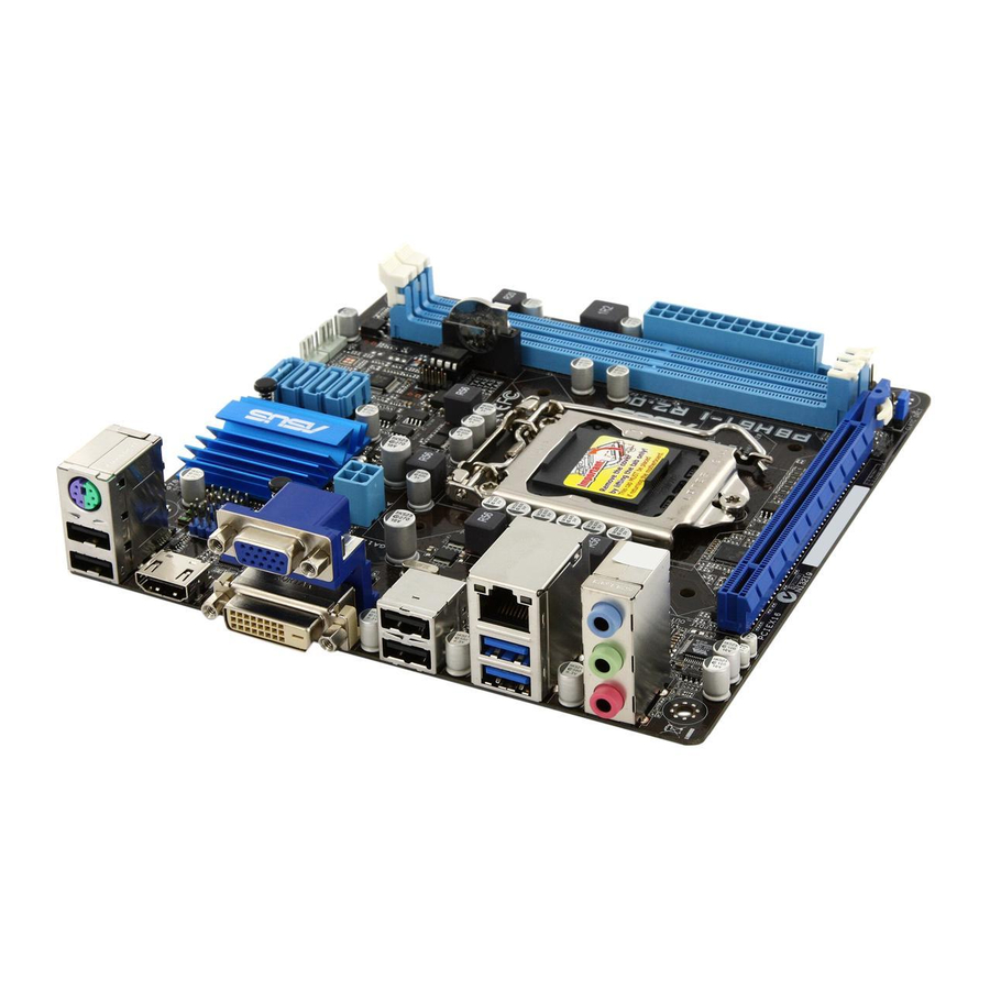
Page 12: Motherboard Overview
Place four screws into the holes indicated by circles to secure the motherboard to the chassis. Do not overtighten the screws! Doing so can damage the motherboard. Place this side towards the rear of the chassis ASUS P8H61-I LX R2.0... -
Page 13: Motherboard Layout
1.2.3 Motherboard layout 17cm(6.7in) SATA3G_1 KBMS CPU_FAN CHA_FAN SATA3G_2 Intel ® SATA3G_3 Super SATA3G_4 64Mb BIOS Lithium Cell CMOS Power ATX12V CLRTC 8111F USB34 LAN1_USB12 AUDIO AAFP SPDIF_OUT VT1708S PCIEX16 SB_PWR 1.2.4 Layout contents Connectors/Jumpers/Slots/LED Page Connectors/Jumpers/Slots/LED Page Clear RTC RAM (3-pin CLRTC) 1-16 System panel connector (10-1 pin F-PANEL) 1-22... -
Page 14: Central Processing Unit (Cpu)
Contact your retailer immediately if the PnP cap is missing, or if you see any damage to the PnP cap/socket contacts/motherboard components. ASUS will shoulder the cost of repair only if the damage is shipment/transit-related. • Keep the cap after installing the motherboard. ASUS will process Return Merchandise Authorization (RMA) requests only if the motherboard comes with the cap on the LGA1155 socket. -
Page 15: Installing The Cpu
1.3.1 Installing the CPU The LGA1156 CPU is incompatible with the LGA1155 socket. DO NOT install a LGA1156 CPU on the LGA1155 socket. Chapter 1: Product introduction... - Page 16 ASUS P8H61-I LX R2.0...
-
Page 17: Installing The Cpu Heatsink And Fan
1.3.2 Installing the CPU heatsink and fan The Intel LGA1155 processor requires a specially designed heatsink and fan assembly to ® ensure optimum thermal condition and performance. Apply the Thermal Interface Material to the CPU heatsink and CPU before you install the heatsink and fan if necessary. - Page 18 To uninstall the CPU heatsink and fan assembly ASUS P8H61-I LX R2.0...
-
Page 19: System Memory
System memory 1.4.1 Overview The motherboard comes with two Double Data Rate 3 (DDR3) Dual Inline Memory Modules (DIMM) sockets. A DDR3 module has the same physical dimensions as a DDR2 DIMM but is notched differently to prevent installation on a DDR2 DIMM socket. DDR3 modules are developed for better performance with less power consumption. -
Page 20: Memory Configurations
• The Max. 16GB memory capacity can be supported with DIMMs of 8GB (or above). ASUS will update the QVL once the DIMMs are available in the market. • For system stability, use a more efficient memory cooling system to support a full memory load (2 DIMMs) or overclocking condition. - Page 21 DDR3-2400 MHz capability DIMM socket support (Optional) Chip Chip Vendors Part No. Size Timing Voltage Brand 1 DIMM 2 DIMMs CORSAIR CMGTX8(XMP) 8GB (2GBx 4) SS - 10-12-10-27 1.65V • • F3-19200CL11Q- G.SKILL 16GB (4 x4GB) DS - 11-11-11-31 1.65V •...
- Page 22 8GB(4 x 2GB) 9-9-9-24 1.65V • • Crucial BL25664BN1608.16FF(XMP) 6GB(3 x 2GB) • • G.SKILL F3-12800CL9D-2GBNQ(XMP) 2GB(2 x 1GB) 9-9-9-24 1.5V • • G.SKILL F3-12800CL7D-4GBRH(XMP) 4GB(2 x 2GB) 7-7-7-24 1.6V • • (continued on the next page) 1-12 ASUS P8H61-I LX R2.0...
-
Page 23: Channel Memory Configuration
• 1 DIMM*: Supports one module inserted into either slot as single-channel memory configuration. • 2 DIMMs*: Supports one pair of modules inserted into both slots as one pair of dual- channel memory configuration. Visit the ASUS website at www.asus.com for the latest QVL. Chapter 1: Product introduction 1-13... -
Page 24: Installing A Dimm
DIMM. Support the DIMM lightly with your fingers when pressing the retaining clips. The DIMM might get damaged when it flips out with extra force. DIMM notch Remove the DIMM from the socket. 1-14 ASUS P8H61-I LX R2.0... -
Page 25: Expansion Slots
Expansion slots In the future, you may need to install expansion cards. The following sub-sections describe the slots and the expansion cards that they support. Unplug the power cord before adding or removing expansion cards. Failure to do so may cause you physical injury and damage motherboard components. -
Page 26: Jumpers
• You do not need to clear the RTC when the system hangs due to overclocking. For system failure due to overclocking, use the CPU Parameter Recall (C.P.R.) feature. Shut down and reboot the system, then the BIOS automatically resets parameter settings to default values. 1-16 ASUS P8H61-I LX R2.0... -
Page 27: Connectors
Connectors 1.7.1 Rear panel connectors PS/2 Mouse (Green). This port is for a PS/2 mouse. LAN (RJ-45) port. This port allows Gigabit connection to a Local Area Network (LAN) through a network hub. Refer to the table below for the LAN port LED indications. LAN port LED indications Speed Activity Link... -
Page 28: Internal Connectors
Front Panel Type item in the BIOS setup to [HD]. If you want to connect an AC'97 front panel audio module to this connector, set the item to [AC97]. By default, this connector is set to [HD]. See section 2.5.6 Onboard Devices Configuration for details. 1-18 ASUS P8H61-I LX R2.0... - Page 29 The system may become unstable or may not boot up if the power is inadequate. • If you are uncertain about the minimum power supply requirement for your system, refer to the Recommended Power Supply Wattage Calculator at http://support.asus. com/PowerSupplyCalculator/PSCalculator.aspx?SLanguage=en-us for details. Speaker connector (4-pin SPEAKER) The 4-pin connector is for the chassis-mounted system warning speaker.
- Page 30 USB_P8- USB_P6- USB_P7- USB_P5- USB_P8+ USB_P6+ USB_P7+ USB_P5+ P8H61-I LX R2.0 USB2.0 connector Never connect a 1394 cable to the USB connectors. Doing so will damage the motherboard! The USB module cable is purchased separately. 1-20 ASUS P8H61-I LX R2.0...
- Page 31 Intel H61 Serial ATA 3.0Gb/s connectors (7-pin SATA3G_1~4) ® These connectors connect to Serial ATA 3.0 Gb/s hard disk drives and optical drives via Serial ATA 3.0 Gb/s signal cables. SATA3G_1 SATA3G_2 SATA3G_3 SATA3G_4 P8H61-I LX R2.0 SATA 3.0Gb/s connectors •...
- Page 32 Power/Soft-off button (2-pin PWRBTN) This 2-pin connector is for the system power button. • Reset button (2-pin RESET) This 2-pin connector is for the chassis-mounted reset button for system reboot without turning off the system power. 1-22 ASUS P8H61-I LX R2.0...
-
Page 33: Software Support
The contents of the Support DVD are subject to change at any time without notice. Visit the ASUS website at www.asus.com for updates. To run the Support DVD Place the Support DVD into the optical drive. - Page 34 1-24 ASUS P8H61-I LX R2.0...
-
Page 35: Chapter 2 Bios Information
BIOS in the future. Copy the original motherboard BIOS using the ASUS Update utility. 2.1.1 ASUS Update utility The ASUS Update is a utility that allows you to manage, save, and update the motherboard BIOS in Windows environment. ®... -
Page 36: Asus Ez Flash 2
Follow the onscreen instructions to complete the updating process. 2.1.2 ASUS EZ Flash 2 The ASUS EZ Flash 2 feature allows you to update the BIOS without using an OS-based utility. Before you start using this utility, download the latest BIOS file from the ASUS website at www.asus.com. -
Page 37: Asus Crashfree Bios 3 Utility
2.1.3 ASUS CrashFree BIOS 3 utility The ASUS CrashFree BIOS 3 is an auto recovery tool that allows you to restore the BIOS file when it fails or gets corrupted during the updating process. You can restore a corrupted BIOS file using the motherboard support DVD or a USB flash drive that contains the updated BIOS file. -
Page 38: Asus Bios Updater
2.1.4 ASUS BIOS Updater The ASUS BIOS Updater allows you to update BIOS in DOS environment. This utility also allows you to copy the current BIOS file that you can use as a backup when the BIOS fails or gets corrupted during the updating process. -
Page 39: Updating The Bios File
Updating the BIOS file To update the BIOS file using BIOS Updater At the FreeDOS prompt, type bupdater /pc /g and press <Enter>. D:\>bupdater /pc /g The BIOS Updater screen appears as below. ASUSTek BIOS Updater for DOS V1.18 Current ROM Update ROM BOARD: P8H61-I LX R2.0... -
Page 40: Bios Setup Program
• The BIOS setup screens shown in this section are for reference purposes only, and may not exactly match what you see on your screen. • Visit the ASUS website at www.asus.com to download the latest BIOS file for this motherboard. -
Page 41: Bios Menu Screen
BIOS menu screen The BIOS setup program can be used under two modes: EZ Mode and Advanced Mode. You can change modes from the Exit menu or from the Exit/Advanced Mode button in the EZ Mode/Advanced Mode screen. EZ Mode By default, the EZ Mode screen appears when you enter the BIOS setup program. -
Page 42: Advanced Mode
The Advanced Mode provides advanced options for experienced end-users to configure the BIOS settings. The figure below shows an example of the Advanced Mode. Refer to the following sections for the detailed configurations. To access the EZ Mode, click Exit, then select ASUS EZ Mode. Menu items Menu bar... -
Page 43: Menu Items
Menu items The highlighted item on the menu bar displays the specific items for that menu. For example, selecting Main shows the Main menu items. The other items (Ai Tweaker, Advanced, Monitor, Boot, Tool, and Exit) on the menu bar have their respective menu items. -
Page 44: Main Menu
RAM to clear the BIOS password. See section 1.9 Jumpers for information on how to erase the RTC RAM. • The Administrator or User Password items on top of the screen show the default Not Installed. After you set a password, these items show Installed. 2-10 ASUS P8H61-I LX R2.0... -
Page 45: Administrator Password
Administrator Password If you have set an administrator password, we recommend that you enter the administrator password for accessing the system. Otherwise, you might be able to see or change only selected fields in the BIOS setup program. To set an administrator password: Select the Administrator Password item and press <Enter>. -
Page 46: Ai Tweaker Menu
Target CPU Turbo-Mode Speed : xxxxMHz Displays the current CPU Turbo-Mode speed. Target DRAM Speed : xxxxMHz Displays the current DRAM speed. 2.4.1 ASUS MultiCore Enhancement [Enabled] [Enabled] Sets to [Enabled] for maximum performance under XMP/Manual/User- defined memory frequency mode. [Disabled] Set to [Disabled] for default core ratio settings. -
Page 47: Memory Frequency [Auto]
2.4.2 Memory Frequency [Auto] Allows you to set the memory operating frequency. Configuration options: [Auto] [DDR3- 800MHz] [DDR3-1066MHz] [DDR3-1333MHz] [DDR3-1600MHz] [DDR3-1866MHz] [DDR3- 2133MHz] [DDR3-2400MHz] Selecting a very high memory frequency may cause the system to become unstable! If this happens, revert to the default setting. 2.4.3 iGPU Max. - Page 48 Use <+>/<-> to adjust the value. Short Duration Power Limit [Auto] Use <+>/<-> to adjust the value. Primary Plane Current Limit [Auto] Use <+>/<-> to adjust the value. Secondary Plane Current Limit [Auto] Use <+>/<-> to adjust the value. 2-14 ASUS P8H61-I LX R2.0...
-
Page 49: Advanced Menu
Advanced menu The Advanced menu items allow you to change the settings for the CPU and other system devices. Be cautious when changing the settings of the Advanced menu items. Incorrect field values can cause the system to malfunction. 2.5.1 CPU Configuration The items in this menu show the CPU-related information that the BIOS automatically detects. -
Page 50: Cpu Power Management Configuration
Allows you to disable or enable the CPU C3 report to OS. [Auto] Set this item automatically. [Enabled] Enables the C3 report function. This item should be enabled in order to enable the Enhanced Halt State. [Disabled] Disables this function. 2-16 ASUS P8H61-I LX R2.0... -
Page 51: Pch Configuration
CPU C6 Report [Auto] Allows you to disable or enable the CPU C6 report to OS. [Auto] Set this item automatically. [Enabled] Enables the C6 report function. This item should be enabled in order to enable the Enhanced Halt State. [Disabled] Disables this function. -
Page 52: Sata Configuration
Configuration options: [Auto] [iGPU] [PCIE] iGPU Memory [Auto] Allows you to select the amount of system memory allocated to DVMT 5.0 used by the iGPU. Configuration options: [Auto] [32M] [64M] [96M] [128M] ~ [416M] [448M] [480M] [512M] 2-18 ASUS P8H61-I LX R2.0... -
Page 53: Usb Configuration
Render Standby [Enabled] Allows you to enable the Intel Graphics Render Standby support to reduce the iGPU ® power use when idle. Configuration options: [Disabled] [Enabled] iGPU Multi-Monitor [Disabled] Allows you to enable or disable the iGPU Multi-Monitor. For Lucid Virtu Universal MVP function support, set this item to [Enabled] to empower both the integrated and discrete graphic cards. -
Page 54: Apm
This item allows user to disable or enable the Ipv4 PXE Boot support. Configuration options: [Disable Link] [Enable] Ipv6 PXE Support [Enabled] This item allows user to disable or enable the Ipv6 PXE Boot support. Configuration options: [Disable Link] [Enable] 2-20 ASUS P8H61-I LX R2.0... -
Page 55: Monitor Menu
Monitor menu The Monitor menu displays the system temperature/power status, and allows you to change the fan settings. Scroll down to display the following items: 2.6.1 CPU Temperature / MB Temperature [xxxºC/xxxºF] The onboard hardware monitor automatically detects and displays the CPU and motherboard temperatures. -
Page 56: Cpu Q-Fan Control [Enabled]
This item appears only when you enable the Chassis Q-Fan Control feature and allows you to set the appropriate performance level of the chassis fan. [Standard] Sets to [Standard] to make the chassis fan automatically adjust depending on the chassis temperature. 2-22 ASUS P8H61-I LX R2.0... -
Page 57: Anti Surge Support [Disabled]
[Silent] Sets to [Silent] to minimize the fan speed for quiet chassis fan operation. [Turbo] Sets to [Turbo] to achieve maximum chassis fan speed. [Manual] Sets to [Manual] to assign detailed fan speed control parameters. The following four items appear only when you set Chassis Fan Profile to [Manual]. Chassis Upper Temperature [70] Use the <+>... -
Page 58: Boot Menu
[Disabled] Disables the full screen logo display feature. Set this item to [Enabled] to use the ASUS MyLogo 2™ feature. Post Report [5 sec] This item appears only when the Full Screen Logo item is set to [Disabled] and allows you to set the waiting time for the system to display the post report. -
Page 59: Option Rom Messages [Force Bios]
• To select the boot device during system startup, press <F8> when ASUS Logo appears. • To access Windows OS in Safe Mode, do any of the following: - Press <F5>... -
Page 60: Tools Menu
> ASUS O.C. Profile 2.8.1 ASUS EZ Flash Utility Allows you to run ASUS EZ Flash 2. Press [Enter] to launch the ASUS EZ Flash 2 screen. For more details, see section 2.1.2 ASUS EZ Flash 2. 2.8.2 ASUS SPD Information... -
Page 61: Exit Menu
Load Optimized Defaults Save Changes & Reset Discard Changes & Exit ASUS EZ Mode Launch EFI Shell from filesystem device Load Optimized Defaults This option allows you to load the default values for each of the parameters on the Setup menus. - Page 62 2-28 ASUS P8H61-I LX R2.0...
-
Page 63: Appendices
: (1) cet appareil ne doit pas provoquer d’interférences et (2) cet appareil doit accepter toute interférence, y compris celles susceptibles de provoquer un fonctionnement non souhaité de l’appareil. ASUS P8H61-I LX R2.0... -
Page 64: Canadian Department Of Communications Statement
ASUS Recycling/Takeback Services ASUS recycling and takeback programs come from our commitment to the highest standards for protecting our environment. We believe in providing solutions for you to be able to responsibly recycle our products, batteries, other components as well as the packaging materials. Please go to http://csr.asus.com/english/Takeback.htm for the detailed recycling information in different... -
Page 65: Asus Contact Information
+1-510-739-3777 +1-510-608-4555 Web site usa.asus.com Technical Support Telephone +1-812-282-2787 Support fax +1-812-284-0883 Online support support.asus.com ASUS COMPUTER GmbH (Germany and Austria) Address Harkort Str. 21-23, D-40880 Ratingen, Germany +49-2102-959911 Web site www.asus.de Online contact www.asus.de/sales Technical Support Telephone (Component) +49-1805-010923*...
Need help?
Do you have a question about the P8H61-I LX R2.0 and is the answer not in the manual?
Questions and answers