Table of Contents
Advertisement
Advertisement
Table of Contents

Related Manuals for Pioneer DEQ-P90


Summary of Contents for Pioneer DEQ-P90
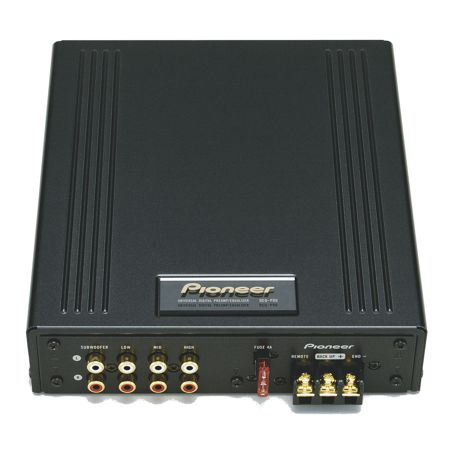
- Page 1 Universal Digital Preamp / Equalizer Owner’s Manual DEQ-P90 English...
-
Page 2: Table Of Contents
Contents Key Finder ............ 3 Audio Adjustment ........9 Head Unit (DEX-P90RS) ........3 Audio Menu ............9 Remote Control (DEX-P90RS) ......3 Switching to the Audio Menu Opening and Closing the Remote Control Cover ......4 Audio Adjustment <Main> ....11 When the Cover is Closed Main Menu ............ - Page 3 Audio Adjustment <Network> ....23 Display for the Person who Set Up the Audio Adjustments ....41 What is the Multi-Amp System? ....23 Network Menu ..........24 Inputting the Name .......... 41 Switching to the Network Menu Inputting Characters ........41 Time Alignment Adjustment ......
-
Page 4: Key Finder
Key Finder Head Unit (DEX-P90RS) This unit can be operated with the combined Head Unit DEX-P90RS (sold separately). 5/∞/2/3 buttons BAND button Remote Control (DEX-P90RS) Most of all functions can be operated by the remote control. Opening the cover enables the SHIFT, RETURN and FUNCTION buttons 1–6 inside the remote control. -
Page 5: Opening And Closing The Remote Control Cover
Opening and Closing the Remote Control Cover When the remote control is opening the cover enables the SHIFT, RETURN and FUNC- TION buttons 1–6 inside the unit. Menu displays with cover open and closed in this system, the available functions and the menu display vary depending on the condition of the remote control in use. -
Page 6: When The Cover Is Closed
Key Finder When the Cover is Closed Closing the cover of the remote control makes the menu display to the closed state. Menu display in closed state Example: Main Menu Screen Note: • Menu display in closed state: Current mode and functions which are ON are displayed. When the Cover is Open Opening the cover of the remote control makes the menu display to the open state. -
Page 7: Before Using This Product
Before Using This Product About This Product This product is universal digital preamp/equalizer which can be operated with the com- bined head unit DEX-P90RS (sold separately). You can operate a number of Audio Adjustment functions with separately sold head unit. About This Manual This product features a number of sophisticated functions ensuring superior reception and operation. -
Page 8: Mode Switch Setting
Before Using This Product MODE Switch Setting This product equipped two setting modes. The one is LR/IND mode and the other is LR/COM mode. LR/IND mode can be adjusted the equalizer and network adjustment independently between Left and Right channel. LR/COM mode can be adjusted these adjustment simultaneously between Left and Right channel. -
Page 9: Precaution
• Protect the product from moisture. • If the battery is disconnected, the preset memory will be erased and must be repro- grammed. • Should this product fail to operate properly, contact your dealer or nearest authorized Pioneer Service Station. -
Page 10: Audio Adjustment
Audio Adjustment Audio Menu This system has the following three Audio Menus: Main <Main> (page 11) This carries out Fader/Balance Adjustments as well as Bass/Treble Adjustment, the basis for sound quality adjustments. It also sets up and adjusts the Position Selector, which cor- rects the orientation of the sound image for the listener’s position in the vehicle. -
Page 11: Switching To The Audio Menu
Switching to the Audio Menu When the system is ON, you can adjust the sound quality. 1. Each press of MENU button selects the desired Audio Menu in the following order: Main (Main Menu) = Equalizer (Equalizer Menu) = Network (Network Menu) 2. -
Page 12: Audio Adjustment
Audio Adjustment <Main> Main Menu With this menu, you can make the following adjustments. • Fader/Balance Adjustment <FAD/BAL CONTROL> (Closed state) • Bass/Treble Adjustment <B/T> (Open state) • Listening Position Adjustment <PS> (Open state) • Source Level Adjustment <SLA> (Open state) Switching to the Main Menu •... -
Page 13: Bass/Treble Adjustment
Bass/Treble Adjustment <B/T> (Open state) It is possible to select one from a choice of four frequencies to becomes the reference when adjusting the bass/treble tone. The frequencies and level adjustment ranges from which selections may be made are as follows: Bass : 63 Hz, 100 Hz, 160 Hz, 250 Hz Treble: 4 kHz, 6.3 kHz, 10 kHz, 16 kHz Level adjustment range: –12 dB –... -
Page 14: Adjusting The Listening Position
Audio Adjustment <Main> Adjusting the Listening Position <PS> (Open state) One way to assure a more natural sound is to clearly position the stereo sound image (putting you in the center of the sound field). The Position Selector function adjusts distance and volume level of sound from each speaker to match seat positions and the number of people in the car, and lets you recall set- tings at the touch of a button. -
Page 15: Fine Tuning The Position
Fine Tuning the Position After choosing the position using the Position Selector function, it is possible to fine tune the distance and the difference in sound levels. Conduct the fine tuning to match the loca- tion of the left and right speakers and the shape of the car and correct the position of the sound image so that the sounds are most natural. - Page 16 Audio Adjustment <Main> 4. Press the 2/3 buttons to correct the position of the sound image. Holding down these buttons continues their operations (during distance tuning, holding down the button moves the distance 3.4 cm/1 step). 5. After tuning has been completed, press the RETURN button to cancel the Position Fine Tuning Screen.
-
Page 17: Effective Distance Adjustment
Effective distance Adjustment Using the Position Fine Tuning function — Relation to Time Alignment Adjustment function — When the system comprises a multi-amp system, the distance between the listening posi- tion and each speaker can be tuned using either of two methods. Time Alignment Adjustment function of the Network Menu (page 25) The distance between the listening position and each speaker of each band (high, mid, low and subwoofer) can be adjusted for the left and right speakers. -
Page 18: Source Level Adjustment
Audio Adjustment <Main> Source Level Adjustment <SLA> (Open state) The SLA (Source Level Adjustment) function prevents radical leaps in volume level when switching between sources. Settings are based on the FM volume level, which remains unchanged. 1. Compare the FM volume with the volume of the other source (refer to DEX-P90RS (sold separately) Owner’s Manual). -
Page 19: Audio Adjustment
Audio Adjustment <Equalizer> About the Equalizer Menu One important factor for creating quality sound is the correction of disturbances in fre- quency characteristics within the complex shape of a vehicle interior. Reflected sounds have a strong effect on direct sound in a vehicle because of the vehicle’s shape, the confined space, absorption of sound by the seats and reflection from the win- dows. -
Page 20: Relation Between Frequency Characteristics And Sound Quality
Audio Adjustment <Equalizer> Relation Between Frequency Characteristics and Sound Quality Sound quality generally has the following characteristics, depending on the frequency. Refer to these characteristics when making adjustments. Soprano Cymbals A lto Tenor Baritone Bass V i o l i n G u i t a r P i a n o Tr u m p e t... - Page 21 The points when adjusting the equalizer curve • Take the recreated frequency bands of the speakers into consideration when adjusting. For example, when a speaker with a band between 80 Hz and 4 kHz is connected, adjusting the level in 50 Hz or 10 kHz will have no effect.
-
Page 22: Adjusting The 31 Band Graphic Equalizer
Audio Adjustment <Equalizer> Adjusting the 31 Band Graphic Equalizer <FINE> (Open state) Adjustable frequency : 20 Hz — 20 kHz (Every 1/3 octaves, total 31 bands) Level adjustment range: –12 dB — +12 dB (0.5 dB/1 step) 1. Open the cover of the remote control in the Equalizer Menu (refer to page 4). -
Page 23: The Flat Function
The Flat function <FLT> (Open state) The adjusted equalizer curve can be temporarily returned to its prior status before making the adjustment (all levels are 0 dB), using the Flat function. This is convenient for checking the effects of the adjusted equalizer curve. 1. -
Page 24: Audio Adjustment
Audio Adjustment <Network> What is the Multi-Amp System? The multi-speaker system reproduces each frequency band (high, mid, low and ultrabass- ranges) through its own exclusive speaker unit. The multi-amp system provides an exclusive power amplifier for each speaker unit. There is only limited space in a vehicle for installing speakers, and it is difficult to install large-diameter speakers in a door or on the dashboard and get high sound quality. -
Page 25: Network Menu
Network Menu <N.W.> With this menu, you can make the following adjustments. • Time Alignment Adjustment <T.A.> (Open state) • Filter Adjustment <FTR> (Open state) • Memory functions of Adjusted Network (Open state) (Refer to page 34.) Switching to the Network Menu •... -
Page 26: Switching To The Network Menu
Audio Adjustment <Network> Time Alignment Adjustment <T.A.> (Open state) In the vehicle, the different speaker units are at widely differing distances from the listener. The sounds from the speakers therefore reach the listener at different times. When a multi-amp system is set up, this causes different delays for each frequency band (high, mid, low and ultrabass-ranges), marring the position of the sound image and the overall balance and disturbing the frequency characteristics. - Page 27 Example: making corrections for the driver’s seat in a left-hand drive vehicle • Measure the distance between the head of the listener, when sitting in the driver’s seat, and each speaker unit. Note: • The unit of distance must be centimeters. Left Speaker (L) Right Speaker (R) Front tweeter...
-
Page 28: Inputting The Distance To Be Corrected
Audio Adjustment <Network> Inputting the Distance to be Corrected (Delay Time) Scope of adjustment: 0 – 340.0 cm (1.7 cm/1 step) 1. Open the cover of the remote control in the Network Menu (refer to page 4). This switches to Network Menu Setting Screen. 2. - Page 29 6. Press the 5/∞ buttons to input the distance to be corrected (delay time). Input the distance to be corrected, as measured on page 26. Holding down these buttons continues their operations (during distance tuning, holding down the button moves the distance 3.4 cm/1 step).
-
Page 30: Filter Adjustment
Audio Adjustment <Network> Filter Adjustment <FTR> (Open state) The following adjustments can be made during filter adjustments. Make the appropriate adjustments for the reproduced frequency band and characteristics of the connected speaker unit. Filter frequency adjustment: Every 1/3 octave Level adjustment: 0.5 dB/1 step The cut-off frequencies of the high pass filter (H.P.F.) and the low pass filter (L.P.F.) of each band (subwoofer, low, mid, high) and the reproduction level of each band are set up. -
Page 31: Switching To The Filter Adjustment Mode
About the H.P.F. and L.P.F. High pass filter eliminates lower sound ranges (low-range) from the set up frequencies and allows high ranges through. Low pass filter eliminates upper sound ranges (high-range) from the set up frequencies and allows low ranges through. About the slope This value indicates how many dB the signals attenuate when the frequency increases (or decreases) 1 octave (unit: dB/oct.). -
Page 32: Adjusting The Filter
Audio Adjustment <Network> Adjusting the Filter First, determine the approximate band to be used, taking into consideration the reproduced frequency band and the characteristics of the connected speaker. 1. Open the cover of the remote control in the Network Menu (refer to page 4). This switches to Network Menu Setting Screen. - Page 33 7. Press the 5/∞ buttons and adjust the level of each band. Holding down these buttons continues their operations. Switch to each band and adjust the level in order to create a better overall balance. 8. Press FUNCTION button 3 and adjust the slope of each filter.
- Page 34 Audio Adjustment <Network> Important points in adjusting the slope • A decrease in the absolute value of the slope (more gentle inclination) makes the frequency characteristics more susceptible to interference from the next band. • Increasing the absolute value of the slope (sharper inclination) lessens the connections between bands, giving the listener the impression of hearing separate, unrelated sounds.
-
Page 35: Audio Adjustment
Audio Adjustment <Memory Functions> Memory Functions of Adjusted Audio Menu (MEMO) This system allows the contents of the adjusted equalizer and network to be stored in mem- ory as follows. The numbers in ( ) represent the numbers of the memory registers to be used. -
Page 36: Switching To Memory Mode
Audio Adjustment <Memory Functions> Switching to Memory Mode Memory operations are conducted in the memory mode of each Audio Menu. Equalizer Menu 1. Open the cover of the remote control in the Equalizer Menu (refer to page 4). 2. Press the SHIFT button. The display switches to Equalizer Memory Operation Screen for conducting memory operations. -
Page 37: Network Menu
Storing the Adjustment Data in Memory 1. Adjust each Audio Menu. Equalizer Menu (page 18) Network Menu (page 23) 2. Switch to the memory mode of each menu (refer to page 34). The display switches to Memory Operation Screen of each menu. 3. -
Page 38: Recalling Data Stored In Memory
Audio Adjustment <Memory Functions> Recalling Data Stored in Memory There are two ways to recall data stored in memory. In Forward/Reverse Order — Functions of Equalizer Menu — This function can be operated when the cover of the remote control is closed. Stored data can be recalled by moving forwards or backwards through the memory numbers (the num- bers of the corresponding FUNCTION buttons). - Page 39 Specifying the Memory Number Directly 1. Switch to the memory mode of each menu (refer to page 35). The display switches to Memory Operations Screen of each menu. 2. Press the FUNCTION button to recall the memory. Press the FUNCTION button which corresponds to the desired memory number. Memory recall operations on the Equalizer Menu •...
-
Page 40: Memory Protect Function
Audio Adjustment <Memory Functions> Memory Protect function In order to avoid accidentally erasing data which have been stored in memory, or to avoid replacing stored data, it is possible to set up a Protect function for the following memory numbers. When the Protect function is ON, adjustment data storage operations are not accepted. -
Page 41: Memory Clearing Operations
Memory Clearing Operations It is possible to clear the memory of the equalizer and network. Clearing operations are conducted as follows. 1. Recall the memory to be cleared by clearing operation (refer to page 38). Specify the memory number directly to recall the memory. 2. -
Page 42: Display For The Person Who Set Up The Audio Adjustments
Display for the Person who Set Up the Audio Adjustments Inputting the Name Inputting the name of the person who set up the memory (Equalizer and Network) of the Audio menu, or messages, stores them in the DEX-P90RS’ head unit’s memory. The DEX-P90RS head unit is sold separately. - Page 43 4. Switch the desired character type with FUNCTION button 1. Each press of FUNCTION button 1 changes the Character type in the fol- lowing order: Upper case alphabet (Capital Letter), Numbers and Symbols = Lower case alphabet (Small Letter) = European letters (European Character), such as those with accents (e.g.
- Page 44 Display for the Person who Set Up the Audio Adjustments 7. When you have completed title input, memorize by pressing the FUNCTION button 5. 8. Press the FUNCTION button 6 or RETURN button and return to the previous mode. 9. The contents stored in memory are indicated on the display. Switching the Audio Menu displays on the title screen the contents stored in memory.
-
Page 45: Memory Data Memo
Memory Data Memo Equalizer Frequency 20 Hz 25 Hz 31.5 Hz 40 Hz 50 Hz 63 Hz 80 Hz 100 Hz 125 Hz 160 Hz 200 Hz 250 Hz 315 Hz 400 Hz 500 Hz 630 Hz 800 Hz 1 kHz 1.25 kHz 1.6 kHz 2 kHz... - Page 46 Memory Data Memo Network: Filter characteristics L.P.F. H.P.F. L.P.F. H.P.F. Level Phase Level Phase Frequency Slope Frequency Slope Frequency Slope Frequency Slope HIGH LEFT S.W. HIGH RIGHT S.W. L.P.F. H.P.F. L.P.F. H.P.F. Level Phase Level Phase Frequency Slope Frequency Slope Frequency Slope Frequency...
- Page 47 Network: Time Alignment Position: HIGH S.W. Left (LEFT) Right (RIGHT) Position: HIGH S.W. Left (LEFT) Right (RIGHT) Position: HIGH S.W. Left (LEFT) Right (RIGHT) Position: HIGH S.W. Left (LEFT) Right (RIGHT) Position: HIGH S.W. Left (LEFT) Right (RIGHT)
-
Page 48: Connecting The Units
Connecting the Units WARNING • Never feed power to other equipment by cutting the insulation of the power supply lead of the unit • For traffic safety and to maintain safe driving and tapping into the lead. The current capacity of conditions, keep the volume low enough so that the lead will be exceeded, causing overheating. -
Page 49: Routing The Optical Cable
Keep the cable away from hot spots, such as near the heater out- let. Setting Example Optical cable IP-BUS cable Multi-CD player DEX-P90RS (sold separately) DEQ-P90 (sold separately) RCA Input Amplifier Front Tweeter Front Mid-range Front Woofer Subwoofer... -
Page 50: Connection Diagram
Connecting the Units Connection Diagram IP-BUS cable (supplied) To IP-BUS OUTPUT optical cable (supplied) (black) To Optical OUTPUT (black) IP-BUS INPUT DEX-P90RS Optical INPUT (blue) (blue) Audio system Power Terminal Refer to “Connecting the Power Terminal” on page 51. Fuse (4A) RCA OUTPUT See “Connecting the RCAInput Amprifier.”... -
Page 51: Connecting The Rca Input Amplifier
Connecting the RCA Input Amplifier White For system remote control Blue/white Blue/white White Tweeter Power Amplifier Mid range Power Amplifier Woofer Power Amplifier Subwoofer Power Amplifier... -
Page 52: Connecting The Power Terminal
Connecting the Units Connecting the Power Terminal 1. Put the short-circuit protection cover around the blue/white, yellow and black lead. Be sure to use this cover to prevent short-circuit. Short circuit protection cover 2. Connecting the leads. Securely fasten the leads with terminal screws. G N D B A C K U R E M O T... -
Page 53: Connecting The Ip-Bus And Optical Cable
Connecting the IP-BUS and Optical Cable Connecting the Cables 1. Attach the cable clamp. When plugging the optical cable and IP-BUS cable into the unit, use the supplied cable clamp to prevent the cables from being bent sharply. Attach the cable clamp into the hole. -
Page 54: Attaching The Noise Filter
Connecting the Units Attaching the Noise Filter To prevent the noise, use the supplied noise filter correctly. 1. Attach the supplied noise filter to IP-BUS cable and Optical Cable. 2. Locate the noise filter as close as possible to the unit, and secure with the lock tie. -
Page 55: Installation
Installation Note: • Before finally installing the unit, connect the wiring temporarily, making sure it is all connected up properly, and the unit and the system work properly. • Use only the parts included with the unit to ensure proper installation. The use of unauthorized parts can cause malfunction. -
Page 56: Troubleshooting
2. If connections and settings are correct, press the RESET button. Refer to “Resetting the Microprocessor” on page 7. 3. If the malfunction continues even after pressing the RESET button, contact your dealer or nearest authorized Pioneer Service Station. Checklist Symptom... -
Page 57: Specifications
Specifications GENERAL RCA OUTPUT Power Source ..DC 14.4 V (10.8 — 15.1 V allowable) Frequency response .... 10 Hz — 20 kHz (+0, –1 dB) Grounding system ........Negative type Max. output level/impedance ......4 V/1 kΩ Fuse ................4 A Distortion ...... - Page 58 TEL: (03) 9586-6300 PIONEER ELECTRONICS OF CANADA, INC. 300 Allstate Parkway, Markham, Ontario L3R OP2, Canada TEL: 1-877-283-5901 PIONEER ELECTRONICS DE MEXICO, S.A. de C.V. Blvd.Manuel Avila Camacho 138 10 piso Col.Lomas de Chapultepec, Mexico, D.F. 11000 TEL: 55-9178-4270 Published by Pioneer Corporation.
Need help?
Do you have a question about the DEQ-P90 and is the answer not in the manual?
Questions and answers