Advertisement
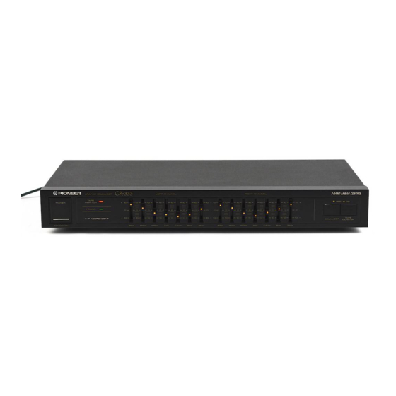
GRAPHIC EQUALIZER
GR-209
THIS MANUAL IS APPLICABLE TO THE FOLLOWING MODEL(S) AND TYPE(S).
Model
Type
GR-209
MYXCN1
SDXCN1
PIONEER ELECTRONIC CORPORATION
PIONEER ELECTRONICS SERVICE, INC. P.O. Box 1760, Long Beach, CA 90801-1760, U.S.A.
PIONEER ELECTRONIC (EUROPE) N.V. Haven 1087, Keetberglaan 1, 9120 Melsele, Belgium
PIONEER ELECTRONICS ASIACENTRE PTE. LTD. 253 Alexandra Road, #04-01, Singapore 159936
c
PIONEER ELECTRONIC CORPORATION 1999
209
STANDBY/ON
Power Requirement
AC220- 230V
AC110/120-127/220/240V
CONTENTS
1. SAFETY INFORMATION ...................................... 2
2. EXPLODED VIEWS AND PARTS LIST ................ 3
3. SCHEMATIC DIAGRAM ....................................... 6
4. PCB CONNECTION DIAGRAM ............................ 8
5. PCB PARTS LIST ............................................... 10
6. ADJUSTMENT .................................................... 10
7. GENERAL INFORMATION ................................ 11
7.1 IC .................................................................. 11
4-1, Meguro 1-Chome, Meguro-ku, Tokyo 153-8654, Japan
ORDER NO.
RRV2147
Remarks
With the voltage selector
T - ZZR MAY 1999 Printed in Japan
Advertisement

Related Manuals for Pioneer GR-209


Summary of Contents for Pioneer GR-209
-
Page 1: Table Of Contents
PIONEER ELECTRONIC CORPORATION 4-1, Meguro 1-Chome, Meguro-ku, Tokyo 153-8654, Japan PIONEER ELECTRONICS SERVICE, INC. P.O. Box 1760, Long Beach, CA 90801-1760, U.S.A. PIONEER ELECTRONIC (EUROPE) N.V. Haven 1087, Keetberglaan 1, 9120 Melsele, Belgium PIONEER ELECTRONICS ASIACENTRE PTE. LTD. 253 Alexandra Road, #04-01, Singapore 159936 PIONEER ELECTRONIC CORPORATION 1999 T –... -
Page 2: Safety Information
The use of a substitute replacement component which does Leakage 0.5mA current Device not have the same safety characteristics as the PIONEER tester under recommended replacement one, shown in the parts list in test this Service Manual, may create shock, fire, or other hazards. -
Page 3: Exploded Views And Parts List
• • • • • Packing Sheet • • • • • CAUTION 220V LABEL See Contrast table (2) (2) CONTRAST TEBLE GR-209/MYXCN1 and SDXCN1 are constructed the same except for the following: Part No. Symbol and Description Mark Remarks MYXCN1 type... - Page 4 GR-209 2.2 EXTERIOR SECTION 10 (1/4 : EQ PCB ) 10 (3/4 : EQ ON/OFF PCB) (2/4 : POWER PCB ) SDXCN1 type Only 10(4/4 : JACK PCB)
- Page 5 Voltage Selector See Contrast table (2) Fuse (630mA/250V) 05005020-063 Fuse Caution Label 15454081-003 (2) CONTRAST TEBLE GR-209/MYXCN1 and SDXCN1 are constructed the same except for the following: Part No. Symbol and Description Mark Remarks MYXCN1 type SDXCN1 type Rear Panel...
-
Page 6: Schematic Diagram
GR-209 3. SCHEMATIC DIAGRAM 3.1 MAIN BOARD ASSY POWER SUPPLY AC220-230V 50/60Hz MY: 01802093-570 MYXCN1 TYPE SD: 01802093-460 SD Only 820/1W AC110/120-127/ AC-2 220/240V 50/60Hz 250V/630mA SDXCN1 05005020-063 AC POWER AC-1 CORD 02360020-004 820/1W 0.22µ/500V IC1B POWER OFF/ON LA64 (LINE OUTPUT MUTE) - Page 7 GR-209 Note : When ordering service parts, be sure to refer to "EXPLODED VIEWS and PARTS LIST" or "PCB PARTS LIST". EQ PCB GRAPHIC EQUALIZER EQ ON/OFF PCB OUTPUT GRAPHIC EQUALIZER OUTPUT 6.8k GRAPHIC EQUALIZER INPUT IC1B LA6458S INPUT BUFFER AMP.
-
Page 8: Pcb Connection Diagram
GR-209 4. PCB CONNECTION DIAGRAM SIDE A 4.1 MAIN BOARD ASSY NOTE FOR PCB DIAGRAMS : 1. Part numbers in PCB diagrams match those in the schematic diagrams. 2. The parts mounted on this PCB include all necessary parts for several destinations. - Page 9 GR-209 SIDE A MAIN BOARD ASSY POWER CORD EQ ON/OFF PCB...
-
Page 10: Pcb Parts List
GR-209 Mark No. Description Part No. Mark No. Description Part No. 5. PCB PARTS LIST • NOTES: Parts marked by "NSP" are generally unavailable because they are not in our Master Spare Parts List. • mark found on some component parts indicates the importance of the safety factor of the part. -
Page 11: General Information
GR-209 7. GENERAL INFORMATION 7.1 IC • The information shown in the list is basic information and may not correspond exactly to that shown in the schematic diagrams. M5229P (MAIN BOARD ASSY : IC2, IC3) • Graphic Equalizer • Pin Arrangement IN 1 –Vcc... - Page 12 GR-209 LA6458S (MAIN BOARD ASSY : IC1) • Input Buffer Amplifier • Pin Arrangement Vcc VOUT1 VIN-1 VIN+1 VIN+2 VIN-2 VOUT2 • Block Diagram VIN+1 VIN+2 VIN-1 VIN-2 VOUT1 VOUT2...
-
Page 13: Panel Facilities And Specifications
GR-209 8. PANEL FACILITIES AND SPECIFICATIONS • FRONT PANEL FACILITIES Left channel Right channel Equalizer Equalizer Equalizer ON indicator indicators indicators STANDBY/ON STANDBY 1 STANDBY/ON switch (STANDBY 3 Equalizer controls These are equalizer controls for the bands 60 Hz, 150 Hz, When this switch is set to the ON position, power is supplied 400 Hz, 1 kHz, 2.4 kHz, 6 kHz and 15 kHz. - Page 14 GR-209 • SPECIFICATIONS Input terminals (Reference input level/Input impedance) Electrical section, miscellaneous INPUT ............150 mV/50 kΩ Power requirements (MYmodel) ... AC 220-230 V, 50/60 Hz Gain ................-2 dB (SD model) ... AC 110/120-127/220/240 V, 50/60 Hz Output terminals (Reference output level/Output impedance) Power consumption ............
Need help?
Do you have a question about the GR-209 and is the answer not in the manual?
Questions and answers