Advertisement
Available languages
Available languages
Table of Contents
- 1 Important Note to the Consumer
- 2 Important Safety Instructions
- 3 Before Starting
- 4 Normal Installation Steps
- 5 Electric Ignition Surface Burners
- 6 Care, Cleaning and Maintenance
- 7 Before You Call for Service
- 8 Model and Serial Number Location
- 9 Antes de Comenzar
- 10 Pasos para la Instalación
- Download this manual
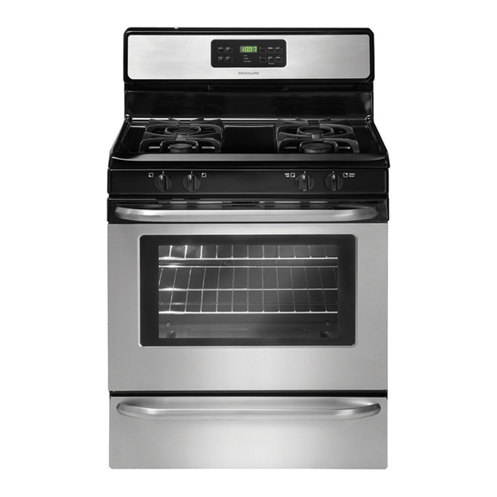
30" GAS RANGE INSTALLATION INSTRUCTIONS
INSTALLATION AND SERVICE MUST BE PERFORMED BY A QUALIFIED INSTALLER.
IMPORTANT: SAVE FOR LOCAL ELECTRICAL INSPECTOR'S USE.
READ AND SAVE THESE INSTRUCTIONS FOR FUTURE REFERENCE.
If the information in this manual is not followed
exactly, a fire or explosion may result causing property
damage, personal injury or death.
FOR YOUR SAFETY:
— Do not store or use gasoline or other flammable vapors
and liquids in the vicinity of this or any other appliance.
— WHAT TO DO IF YOU SMELL GAS:
• Do not try to light any appliance.
• Do not touch any electrical switch; do not use any phone
in your building.
• Immediately call your gas supplier from a neighbor's
phone. Follow the gas supplier's instructions.
• If you cannot reach your gas supplier, call the fire
department.
— Installation and service must be performed by a qualified
installer, service agency or the gas supplier.
OVERALL
DIMENSIONS
30"
48"
Maximum
46
3/8"
door open
Clearances and Dimensions
1. Location—Check location where the range will be
installed. Check for proper electrical and gas supply,
and the stability of the floor.
2. Dimensions that are shown must be used. Given
dimensions provide minimum clearance. Contact
surface must be solid and level.
p/n 316259343 Rev A EN/SP (0809)
(For Models with Sealed Top Burners)
25
3/4"
29
1/4"
incl. door handle
*Minimum to
Side Wall
on Either
Side of
+
1/8"
36
-
Range 5"
36"
29 7/8"
Note: For appliances installed in the
State of Massachusetts see page 2.
30"
30"
Minimum
18"
*5"
30"
0" Clearance Below Cooking Top and at Rear of Range.
Provide Proper Fuel Type
Before Proceeding: Your range is preset to operate on
natural gas.
DO NOT attempt to convert this range to LP/
Propane settings without the proper LP/Propane conversion
kit provided with the range or obtained from your dealer. Follow
all instructions provided with the LP Conversion Kit.
1
Refer to your serial plate for
applicable agency certification
SIDE
FRONT
VIEW
VIEW
Minimum to
Cabinets on
Maximum Depth
Either Side
for Cabinets
of Range.
Above Range Top.
25"
Español - Páginas 9-16
13"
Advertisement
Table of Contents

Related Manuals for Frigidaire 316259343


Summary of Contents for Frigidaire 316259343
- Page 1 2. Dimensions that are shown must be used. Given dimensions provide minimum clearance. Contact surface must be solid and level. p/n 316259343 Rev A EN/SP (0809) (For Models with Sealed Top Burners) 3/4" 1/4"...
-
Page 2: Important Note To The Consumer
• Air curtain or other overhead range hoods, which operate by blowing a downward air flow on to a range, shall not be used in conjunction with gas ranges other than when the hood and range have been designed, tested and listed by an independent test laboratory for use in combination with each other. -
Page 3: Before Starting
1. Anti-Tip Bracket Installation Instructions Important Safety Warning To reduce the risk of tipping of the range, the range must be secured to the floor by properly installed anti-tip bracket and screws packed with the range. Failure to install the anti-tip bracket will allow the range to tip over if excessive weight is placed on an open door or if a child climbs upon it. - Page 4 The gas supply line should be 1/2" or 3/4" I.D. 3. Seal wall openings. Seal any openings in the wall behind the range and in the floor under the range after gas supply line is installed. (For Models with Sealed Top Burners) Connect the range to the gas supply.
- Page 5 Make sure service shut-off valve on pressure regulator is in the "ON" position (See Fig. 4f). g) Check for leaks. Turn the gas supply on to the range and use a liquid leak detector at all joints and conduits to check for leaks in the system.
- Page 6 30" GAS RANGE INSTALLATION INSTRUCTIONS 5. Read these electrical connection details first then connect electricity to range. Before servicing, disconnect electrical supply at circuit breaker, fuse or power cord. Electric Requirements: A dedicated, properly grounded and polarized branch circuit protected by a 15 amp. circuit breaker or time delay fuse.
-
Page 7: Electric Ignition Surface Burners
30" GAS RANGE INSTALLATION INSTRUCTIONS 7. Electric Ignition Surface Burners Operation of electric igniters should be checked after range and supply line connectors have been carefully checked for leaks and range has been connected to electric power. a. To check for proper lighting, push in and turn a surface burner knob counterclockwise to the LITE position. -
Page 8: Care, Cleaning And Maintenance
(For Models with Sealed Top Burners) 12. Make Sure Range is Level. Level the range by placing a level horizontally on an oven rack. Check diagonally from front to back, then level the range by either adjusting the leveling legs or by placing shims under the corners of the range as needed. - Page 9 2. Las dimensiones que se muestran son las que deben utilizarse. Las dimensiones que se proporcionan dejarán el espacio mínimo. La superficie de contacto debe ser sólida y estar nivelada. p/n 316259343 Rev A EN/SP (0809) (Modelos con quemadores sellados) 3/4" al manga 1/4"...
- Page 10 INSTRUCCIONES DE INSTALACIÓN DE COCINAS DE GAS DE 30" Instrucciones importantes para el instalador Lea todas las instrucciones que se proporcionan en este manual de instalación antes de comenzara instalar la cocina. Retire todo el material de embalaje de los compartimentos del horno antes de conectar el suministro de energía eléctrica y de gas a la cocina.
-
Page 11: Antes De Comenzar
INSTRUCCIONES DE INSTALACIÓN DE COCINAS DE GAS DE 30" Antes de comenzar Herramientas que va a necesitar Para patas de nivelación y montura anti-vuelco: • Llave ajustable o alicates • Llave para apretar tuercas de 5/16" o un destornillador de cabeza plana •... - Page 12 INSTRUCCIONES DE INSTALACIÓN DE COCINAS DE GAS DE 30" C. Nivelación y colocación de la cocina – Para nivelar la cocina, deberá ajustar las cuatro (4) patas de nivelación con una llave. Nota: Es necesario mantener un espacio mínimo de 1/8" entre el fondo de la cocina y la pata de nivelación para dejar espacio suficiente para instalar la montura de sujeción.
- Page 13 INSTRUCCIONES DE INSTALACIÓN DE COCINAS DE GAS DE 30" Fig. 4d Fig. 4e “ ON ” Fig. 4f NO permita que el regulador se mueva sobre la tubería cuando apriete las conexiones. a. Instale una válvula de cierre manual externa en la tubería de suministro de gas en una ubicación accesible por fuera de la estufa.
- Page 14 INSTRUCCIONES DE INSTALACIÓN DE COCINAS DE GAS DE 30" LEA CON DETENIMIENTO. Para su seguridad personal, este producto debe ser debidamente conectado a una toma de tierra. Instrucciones para la toma de tierra El cable del suministro eléctrico de esta aplicación está equipado con un enchufe de 3 patillas (para toma de tierra) que coincida con un enchufe de pared estándar con toma de tierra de 3 patillas para minimizar la posibilidad de que se produzcan...
- Page 15 INSTRUCCIONES DE INSTALACIÓN DE COCINAS DE GAS DE 30" 7. Funcionamiento de los Controles Superiores del Gas: 1. Coloque el utensilio de cocina sobre el quemador superior. 2. Oprima la perilla de control superior y gírela a la izquierda para sacarla de la posición 'OFF'. (Ver Fig. 1). 3.
- Page 16 INSTRUCCIONES DE INSTALACIÓN DE COCINAS DE GAS DE 30" 10. Obturador de Aire - Quemador del horno la longitud aproximada de la llama del quemador de horno es 1 pulgada (interior claro, flama azul). Para determinar si la llama del quemador de horno es la adecuada, retire el fondo del horno y el deflector del quemador y fije el horno en la opción hornear a 300°F.
Need help?
Do you have a question about the 316259343 and is the answer not in the manual?
Questions and answers