Table of Contents
Advertisement
Available languages
Available languages
Quick Links
SmartOnline
Output: User-Selectable 200/220/230/240V AC, 50/60 Hz, 1Ø, 2-Wire + Ground
Copyright © 2009 Tripp Lite. SmartOnline is a trademark of Tripp Lite. All other trademarks are the sole property of their respective owners.
Owner's Manual
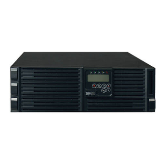
SU10KRT3/1X
Rack/Tower On-Line UPS System
™
with Parallel Redundancy Capability
Input: 160-280/277-485V AC, 50/60 Hz, 3Ø, 4-Wire + Ground, Wye
Not suitable for mobile applications.
1111 W. 35th Street, Chicago, IL 60609 USA
+1.773.869.1234 • www.tripplite.com
2
2
4
5
5
6
6
7
7
7
7
8
8
9
10
10
11
1
12
13
13
13
15
16
16
16
16
17
18
18
19
20
39
58
Advertisement
Chapters
Table of Contents

Related Manuals for Tripp Lite SmartOnline SU10KRT3/1X


Summary of Contents for Tripp Lite SmartOnline SU10KRT3/1X
-
Page 1: Table Of Contents
Русский 6-2 Control Panel Error Codes 1111 W. 35th Street, Chicago, IL 60609 USA +1.773.869.1234 • www.tripplite.com Copyright © 2009 Tripp Lite. SmartOnline is a trademark of Tripp Lite. All other trademarks are the sole property of their respective owners. -
Page 2: Introduction
1 – Introduction Tripp Lite’s SmartOnline Rack/Tower On-Line UPS System with Parallel Redundancy Capability provides long-lasting battery backup for data centers, telecommunications, networks, industrial facilities, security, emergency systems and other critical applications that require high capacity, high availability and extended runtime. True on-line operation continuously transforms 3-phase input power into precision-regulated single-phase output to guarantee maximum equipment protection and stability. -
Page 3: Wiring Warnings
• The batteries are recyclable. Refer to local codes for disposal requirements. Do not dispose of batteries except through approved channels in accordance with all applicable local, state and national regulations. • Tripp Lite offers a complete line of UPS system Replacement Battery Cartridges (R.B.C.). Contact Tripp Lite to determine the specific replacement battery for the UPS system. -
Page 4: Rear Panel Features
3 – Rear Panel Features Note: Refer to Section 6-1 for a description of the UPS system’s control panel. UPS System Power Module Rear Panel UTILITY INPUT BREAKER SLOT RS-232 Port (Note: Remove the network card in order to use the RS-232 port.) Settings Switch for Parallel Redundancy Operation CAN Bus Connection Ports for Parallel Redundancy Operation Cooling Fans... -
Page 5: Mounting
4 – Mounting Read Section 2 – Important Safety Instructions Before Mounting Warning: The UPS system is very heavy—be careful when moving or lifting it. 4-1 Unpacking Remove the protective foam and unwrap the unit. Inspect the unit carefully prior to installation. If anything appears to be damaged, contact Tripp Lite for service. -
Page 6: Placement
• Use the included rackmount shelves and mounting hardware to mount the UPS system in a 4-post rack or rack enclosure. To mount the UPS system in a 2-post (telecom) rack, order Tripp Lite’s 2-Post Rackmount Kit (model 2POSTRMKITWM, sold separately). -
Page 7: Mounting (Tower)
4 – Mounting continued 4-4 Mounting (Tower) Warning: When mounting the UPS system in a tower position, make sure the control panel is closer to the top of the cabinet than the bottom. Note: The control panel can be rotated to match the UPS system’s position. Pull the panel out slightly, rotate it and push it back into place. Tower Mounting Procedure To mount the module in an upright, tower position, first determine the fitness of the hardware and procedures. -
Page 8: Electrical And Cable Data
5 – Wiring continued 5-3 Electrical and Cable Data AC Input and Output (75°C Minimum Copper Wire) Maximum Current Conductor Diameter Torque Force 54.3 amperes 4.6 mm (#6 AWG) 2.60 N•m (23 in•lb) 5-4 AC Input/Output Wiring Instructions Use M3 pan-head screws to attach the cable attachment tray beneath the terminal block. -
Page 9: External Battery Pack Connection
Additional external battery packs, sold separately, may be connected to the UPS system for additional battery backup runtime. Contact Tripp Lite customer service to order additional external battery packs. Switch the external battery pack’s DC breaker to the ON position. -
Page 10: Standard Operation
Bypass LED: If an internal fault or overload occurs, the LED will flash repeatedly to show that connected equipment will receive filtered AC line power, but will not receive battery power during a blackout. In this case, contact Tripp Lite for service. -
Page 11: Control Panel Error Codes
6 – Standard Operation continued 6-1 Control Panel Features continued LCD Symbols Symbol Description LINE Utility or Bypass Source Battery Low Battery Abnormal/Fault UPS Overload UPS Operating in Specified Mode (Normal, Economy, etc.) A Transfer to Battery Occurred in the UPS Output UPS Failure to Transfer to Bypass or Bypass Abnormal in ECO Mode Utility Input Abnormal UPS Shutoff... -
Page 12: Normal Mode Startup
6 – Standard Operation continued 6-3 Normal Mode Startup Confirm that the UPS system is properly grounded. Make sure the utility AC supply circuit breaker and the UPS system’s input breaker are switched off. Wire the utility AC supply circuit and output circuit to the UPS system’s terminal block and connect the external battery pack, following the instructions in Section 5 –... -
Page 13: Battery Mode Startup (Cold Start)
6 – Standard Operation continued 6-4 Battery Mode Startup (Cold Start) The UPS system supports battery mode startup (cold start), allowing it to operate as a standalone power source when AC input power is unavailable. Make sure the UPS system is properly installed and the battery is at least partially charged. Some electronic equipment may draw more amps during startup;... -
Page 14: Changing Default Settings
6 – Standard Operation continued 6-6 UPS System Settings and Measurements continued Settings and Special Functions After the UPS starts up completely, press to view settings and execute special functions. Scroll down to review the settings. Use the button to execute special functions. Special functions include buzzer ON or buzzer OFF and self-test OFF or self-test ON... -
Page 15: Parallel Redundancy Operation
7 – Parallel Redundancy Operation (Optional) DANGER! LETHAL HIGH VOLTAGE HAZARD! All wiring should be performed by a qualified electrician, in accordance with the warnings in this manual and all applicable electrical and safety codes. Incorrect wiring may cause serious personal injury and property damage. Read, study and understand the warnings listed in Section 2 –... -
Page 16: Communications
8 – Communications Note: These connections are optional. The UPS system will function without these connections. 8-1 Network Card The UPS system includes an internal network card that provides an Ethernet interface for remote monitoring and control of the UPS system. Refer to the network card documentation for additional information. -
Page 17: Troubleshooting
Reconnect the RJ45 cable or set a UPS with ID=1. Fault LED Other Error Code Have a qualified electrician check the AC supply circuit and wiring, then restart the UPS system. If the problem persists, contact Tripp Lite for service. UPS fails to offer battery Not Applicable Recharge the battery uninterrupted for 12 hours. -
Page 18: Specifications
The UPS system is covered by the limited warranty described in this manual. Extended and on-site warranty options are also available. For more information, call Tripp Lite Customer Service at +1.773.869.1234. If returning the UPS system to Tripp Lite, carefully pack the UPS system using the original packing material that came with the unit. -
Page 19: Warranty
Regulatory Compliance Identification Numbers For the purpose of regulatory compliance certifications and identification, your Tripp Lite product has been assigned a unique series number. The series number can be found on the product nameplate label, along with all required approval markings and information. When requesting compliance information for this product, always refer to the series number. The series number should not be confused with the marking name or model number of the product. -
Page 20: Español
6-2 Códigos de error del panel de control 1111 W. 35th Street; Chicago IL 60609; EE. UU. +1.773.869.1234 • www.tripplite.com Copyright © 2009 Tripp Lite. SmartOnline es una marca registrada de Tripp Lite. Todas las otras marcas registradas son propiedad exclusiva de sus respectivos dueños. -
Page 21: Introducción
1 – Introducción El sistema de UPS de Tripp Lite SmartOnline en línea, para montar en rack/torre, con capacidad de redundancia paralela, proporciona respaldo de batería de larga duración para centros de datos, telecomunicaciones, redes, instalaciones industriales, seguridad, sistemas de emergencia y otras aplicaciones vitales que requieren gran capacidad, disponibilidad y tiempo de funcionamiento extendido. - Page 22 • Tripp Lite ofrece una línea completa de cartuchos de baterías de reemplazo para sistemas de UPS (R.B.C.). Comuníquese con Tripp Lite para determinar la batería de reemplazo específica para su sistema de UPS.
-
Page 23: Características Del Panel Posterior
3 – Características del panel posterior Nota: Consulte la sección 6-1 para obtener una descripción del panel de control del sistema de UPS. Panel posterior del módulo de alimentación del sistema de UPS UTILITY INPUT BREAKER SLOT Puerto RS-232 (Nota: quite la tarjeta de red para poder utilizar el puerto RS-232). Interruptor de configuración para el funcionamiento de redundancia paralela Puertos de conexión de bus CAN para el funcionamiento de redundancia paralela Ventiladores... -
Page 24: Montaje
Quite la espuma protectora y desenvuelva la unidad. Antes de instalar la unidad examínela atentamente. Si algo parece estar dañado, comuníquese con el servicio técnico de Tripp Lite. Guarde los materiales de embalaje para utilizarlos en el futuro. Lista de embalaje: •... -
Page 25: Colocación
• Utilice los estantes y las herramientas de montaje incluidas para montar el sistema de UPS en un rack de 4 puestos o en un gabinete de rack. Para montar el sistema de UPS en un rack de 2 puestos (telecomunicaciones), pida en Tripp Lite un kit para montar en rack de 2 puestos (modelo 2POSTRMKITWM, se vende por separado). -
Page 26: Montaje (Torre)
4 – Montaje (continuación) 4-4 Montaje (Torre) Advertencia: Al montar el sistema de UPS en una posición en torre, asegúrese de que el panel de control esté más cerca de la parte superior del gabinete y que de la inferior. Nota: Se puede rotar el panel de control para que coincida con la orientación del sistema de UPS. -
Page 27: Datos Eléctricos Y De Los Cables
5 – Cableado (continuación) 5-3 Datos eléctricos y de los cables Entrada y salida de CA (cable de cobre de mínimo 75 ºC) Corriente máxima Diámetro del conductor Fuerza de torque 54,3 amperios 4,6 mm (#6 AWG) 2,60 N·m (23 in·lb) 5-4 Instrucciones del cableado de entrada/salida de CA Utilice tornillos de cabeza troncocónica M3 para fijar la bandeja de conexión de cables... -
Page 28: Conexión Del Módulo De Baterías Externas
Se pueden conectar módulos de baterías externas adicionales al sistema de UPS para obtener tiempo respaldo de batería adicional; se venden por separado. Para pedir módulos de baterías externas comuníquese con el servicio al cliente de Tripp Lite. Coloque el disyuntor de CC del módulo de baterías externas en la posición ENCENDIDO. -
Page 29: Funcionamiento Estándar
CA filtrada pero que no serán alimentados por la batería durante un apagón. En este caso, comuníquese con el servicio técnico de Tripp Lite. LED de redundancia paralela: Este LED verde se ilumina cuando el sistema de UPS está funcionando en modo de redundancia paralela. -
Page 30: Códigos De Error Del Panel De Control
6 – Funcionamiento estándar (continuación) 6-1 Características del panel de control (continuación) Símbolos LCD Símbolo Descripción LINE Fuente de la red pública o de derivación Batería baja Batería anormal/falla Sobrecarga del UPS El UPS funciona en el modo especificado (normal, económico, etc.) Ocurrió... -
Page 31: Arranque En Modo Normal
6 – Funcionamiento estándar (continuación) 6-3 Arranque en modo normal Confirmar que el sistema de UPS esté correctamente conectado a tierra. Asegúrese de que el disyuntor de suministro de CA de la red pública y que el disyuntor de entrada del sistema de UPS estén apagados. Conecte el circuito de suministro de CA de la red pública y el circuito de salida al bloque de terminales del sistema de UPS y conecte el módulo de baterías externas siguiendo las instrucciones de la sección 5 –... -
Page 32: Arranque En Modo De Batería (Arranque En Frío)
6 – Funcionamiento estándar (continuación) 6-4 Arranque en modo batería (arranque en frío) El sistema de UPS soporta el arranque en modo batería (arranque en frío), lo que le permite funcionar como fuente de alimentación independiente cuando la tensión CA de entrada no está disponible. Asegúrese de que el sistema de UPS esté... -
Page 33: Configuraciones Y Mediciones Del Sistema De Ups
6 – Funcionamiento estándar (continuación) 6-6 Configuraciones y mediciones del sistema de UPS (continuación) Configuraciones y funciones especiales Después de que el UPS arranque completamente, presione para visualizar las configuraciones y ejecutar las funciones especiales. Desplácese hacia abajo para revisar estas configuraciones. Utilice el botón para ejecutar las funciones especiales. -
Page 34: Funcionamiento Con Redundancia Paralela
7 – Funcionamiento con redundancia paralela (opcional) ¡PELIGRO! ¡RIESGO DE MUERTE POR ALTA TENSIÓN! Todo el cableado debe ser realizado por un electricista calificado, de acuerdo con las advertencias de este manual y los códigos de seguridad y eléctricos correspondientes. El cableado incorrecto puede causar graves lesiones personales y daño a la propiedad. -
Page 35: Comunicaciones
8 – Comunicaciones Nota: Estas conexiones son opcionales. El sistema de UPS funcionará sin estas conexiones. 8-1 Tarjeta de red El sistema de UPS incluye una tarjeta de red interna que proporciona una interfaz Ethernet para monitoreo y control remotos del sistema de UPS. Para obtener información adicional, consulte la documentación de la tarjeta de red. -
Page 36: Resolución De Problemas
• ¿La tensión de entrada de CA de la red pública está dentro del rango aceptable para el sistema de UPS? Si los problemas persisten, consulte las siguientes instrucciones: Si el problema continúa después de seguir las siguientes instrucciones y/o reiniciar el sistema de UPS, comuníquese con Tripp Lite para obtener servicio técnico. Problema Código de error de pantalla LCD Solución posible... -
Page 37: Especificaciones
Para obtener más información, llame al Servicio de atención al cliente de Tripp Lite al +1.773.869.1234. Si desea devolver el sistema de UPS a Tripp Lite, guárdelo cuidadosamente en el material de embalaje original que vino con la unidad. Adjunte una carta... -
Page 38: Garantía
En caso de demostrarse dentro de ese período que el producto tiene defectos de materiales o de mano de obra, el vendedor lo reparará o reemplazará a su exclusiva discreción. El servicio bajo esta garantía incluye las partes y el laboratorio del centro de servicio técnico de Tripp Lite. Tripp Lite cuenta con planes de servicio técnico en el lugar a través de técnicos autorizados (en la mayoría de las áreas). -
Page 39: Français
6-2 Codes d’erreur du panneau de contrôle Русский 1111 W. 35th Street, Chicago, IL 60609 États-Unis +1.773.869.1234 • www.tripplite.com Copyright © 2009 Tripp Lite. SmartOnline est une marque de Tripp Lite. Toutes les autres marques sont détenues uniquement par leur propriétaire respectif. -
Page 40: Introduction
1 – Introduction Le système ASI on-line en rack/tour SmartOnline de Tripp Lite avec redondance parallèle permet de fournir une alimentation de secours durable pour les centres de données, de télécommunications, les systèmes en réseau, les établissements industriels, les systèmes de sécurité et d’urgence et d’autres applications critiques nécessitant un fonctionnement sans interruption à... - Page 41 • Tripp Lite vend une gamme complète de batteries de rechange pour système ASI. Veuillez contacter Tripp Lite pour déterminer le type de batterie de remplacement requis pour le système ASI.
-
Page 42: Caractéristiques Du Panneau Arrière
3 – Caractéristiques du panneau arrière NB : Consultez la Section 6-1 pour une description du panneau de contrôle du système ASI. Panneau arrière du module d’alimentation du système ASI UTILITY INPUT BREAKER SLOT Port RS-232 (NB : retirez la carte réseau pour utiliser le port RS-232.) Interrupteur de réglage pour un fonctionnement en mode parallèle redondant Ports de connexion bus CAN pour fonctionnement en mode parallèle redondant Ventilateurs de refroidissement... -
Page 43: Montage
4-1 Déballage Retirez la mousse protectrice et déballez l’unité. Inspectez soigneusement l’unité avant de l’installer. Si un élément semble endommagé, contactez Tripp Lite pour un entretien. Conservez les matériaux d’emballage pour une utilisation ultérieure. Liste de colisage : • 1 Module d’alimentation ASI •... -
Page 44: Mise En Place
• Utilisez les étagères de montage sur rack et le matériel de montage fournis pour monter le système ASI sur un rack à 4 montants ou une étagère à racks. Pour monter le système ASI sur un rack à 2 montants (télécom), commandez le kit de montage sur rack à 2 montants de Tripp Lite (référence produit 2POSTRMKITWM, vendu séparément). -
Page 45: Montage (Tour)
4 – Montage (suite) 4-4 Montage (tour) Avertissement : Lors du montage du système ASI en position tour, assurez-vous que le tableau de contrôle est le plus près possible du haut du boîtier que du bas. NB : Il est possible de faire tourner le panneau de contrôle en fonction de l’orientation du système ASI. Sortez le panneau en le tirant légèrement, faites-le tourner et poussez-le pour le remettre en position. -
Page 46: Données Électriques Et Câbles
5 – Câblage (suite) 5-3 Données électriques et câbles Entrée et sortie c.a. (fil en cuivre minimum 75 °C) Courant maximum Diamètre du conducteur Couple 54,3 ampères 4,6 mm (numéro 6, calibre américain) 2,60 N.m (23 in.lb) 5-4 Consignes de câblage entrée/sortie c.a. Utilisez des vis à... -
Page 47: Connexion Du Pack Batterie Externe
à chaque extrémité du câble c.c. en le fixant à chaque panneau arrière. Des packs batteries externes supplémentaires (vendus séparément) peuvent être connectés au système ASI pour une durée de fonctionnement supplémentaire de la batterie en mode de secours. Contactez le service clientèle Tripp Lite pour commander des packs batteries externes supplémentaires. -
Page 48: Fonctionnement Standard
Dans ce cas, contacter Tripp Lite pour une révision. LED de redondance parallèle : Cette LED verte s’allume lorsque le système ASI fonctionne en mode de redondance parallèle. -
Page 49: Codes D'erreur Du Panneau De Contrôle
6 – Fonctionnement standard (suite) 6-1 Caractéristiques du panneau de contrôle continued Symbole LCD Symbole Description LINE Source secteur ou dérivation Batterie basse Batterie anormale/Panne Surcharge ASI ASI fonctionnant en mode spécifié (normal, économie, etc.) Un transfert vers la batterie est survenu dans la sortie UPS L’ASI n’a pas réussi à... -
Page 50: Démarrage En Mode Normal
6 – Fonctionnement standard (suite) 6-3 Démarrage en mode normal Vérifiez que le système ASI est bien relié à la terre. Assurez-vous que l’interrupteur de circuit d’alimentation c.a. secteur et l’interrupteur d’entrée du système ASI sont bien sur Off. Câblez le circuit d’alimentation en c.a. secteur et le circuit de sortie à la plaque à borne du système ASI et connectez le pack batterie externe, en suivant les instructions en Section 5 –... -
Page 51: Démarrage En Mode Batterie (Démarrage À Froid)
6 – Fonctionnement standard (suite) 6-4 Démarrage en mode batterie (démarrage à froid) Ce système ASI prend en charge le démarrage en mode batterie (démarrage à froid) : il peut donc être utilisé comme une source d’alimentation autonome si l’alimentation en c.a. n’est pas disponible. Assurez-vous que le système ASI est bien installé... - Page 52 6 – Fonctionnement standard (suite) 6-6 Réglages et mesures du système ASI (suite) Réglages et fonctions spéciales Une fois le démarrage de l’ASI complètement terminé, appuyez pour afficher les réglages et effectuer des fonctions spéciales. Faites défiler vers le bas pour examiner les réglages.
-
Page 53: Fonctionnement En Redondance Parallèle
7 – Fonctionnement en redondance parallèle (en option) DANGER ! HAUTE TENSION, DANGER DE MORT ! Tous les câblages doivent être effectués par un électricien qualifié, en respectant les avertissements de ce manuel et tous les codes électriques et de sécurité en vigueur. Un mauvais câblage peut causer des dommages personnels et matériels graves. Veuillez lire, étudier et comprendre les avertissements figurant en Section 2 –... -
Page 54: Communications
8 – Communications NB : Ces connexions sont en option. Le système ASI fonctionnera sans ces connexions. 8-1 Carte réseau Le système ASI comprend une carte réseau interne qui offre une interface Ethernet pour un suivi et un contrôle à distance du système ASI. Veuillez consulter la documentation de la carte réseau pour tout complément d’informations. -
Page 55: Résolution Des Problèmes
LED de panne Vérifiez les connexions de la batterie, puis rechargez-la pendant 12 Er05 + heures. Si ce problème persiste, contactez Tripp Lite pour une révision et/ ou le remplacement de la batterie. LED de panne Si le disjoncteur s’est déclenché, éteignez complètement le système ASI et Er06/Er10/Er12/Er28 + laissez-le refroidir. -
Page 56: Spécifications
également disponibles. Pour tout complément d’informations, veuillez contacter le service clientèle Tripp Lite au +1.773.869.1234. En cas de retour du système ASI à Tripp Lite, emballez-le soigneusement à l’aide de ses matériaux d’emballage d’origine, fournis avec l’unité. Joignez une lettre décrivant les symptômes du problème. Si le système ASI est toujours couvert par la garantie, joignez une copie de la facture de vente. -
Page 57: Garantiecaractéristiques Eau De C
Si ce produit révélait un défaut matériel ou de fabrication pendant cette période, le vendeur réparera ou remplacera ce produit, à son entière discrétion. Les révisions dans le cadre de cette garantie comprennent les pièces et la main d’œuvre du centre de réparation Tripp Lite. Des options de réparation sur site sont disponibles auprès de Tripp Lite, via des partenaires de réparation agréés (dans la plupart des régions). -
Page 58: Русский
6-2 Коды ошибок, выдаваемые на контрольную панель 6-3 Запуск при работе в стандартном режиме 1111 W. 35th Street, Chicago, IL 60609 USA +1.773.869.1234 • www.tripplite.com Copyright © 2009 Tripp Lite. SmartOnline – торговая марка компании Tripp Lite. Все прочие торговые марки являются исключительной собственностью соответствующих владельцев. -
Page 59: Введение
1 – Введение Онлайновая система ИБП (UPS) SmartOnline с двойным преобразованием и возможностью параллельного резервирования в стоечном/вертикальном исполнении, выпускаемая компанией Tripp Lite, обеспечивает длительное аварийное батарейное питание для центров сбора и обработки данных, телекоммуникационных систем, информационных сетей, промышленного оборудования, систем безопасности, аварийных и других критических важных применений, для которых требуются источники питания с высокой... - Page 60 аккумуляторных батарей по иным каналам и иными способами, помимо тех, что предусмотрены в применимых национальных, региональных и местных нормативных документах. • Компания Tripp Lite предлагает полную линейку запасных аккумуляторных блоков для системы ИБП. Для того чтобы определить тип запасного аккумуляторного блока для вашей системы ИБП, свяжитесь с компанией Tripp Lite.
-
Page 61: Элементы Задней Панели
2 – Основные правила техники безопасности (продолжение) Условные обозначения на этикетке На этикетке изделия встречаются следующие условные обозначения: переменное напряжение положительный вывод аккумуляторной батареи фаза Ø постоянное напряжение отрицательный вывод аккумуляторной батареи “земля” Номер модели, значения напряжения и другая важная информация находятся на этикетке изделия. 3 –... -
Page 62: Установка
Внимание: Силовой модуль ИБП очень тяжелый – соблюдайте осторожность при его поднятии и перемещении. 4-1 Распаковка Удалите упаковочный пенопласт и мягкую упаковку. Перед началом сборки внимательно осмотрите силовой модуль. При обнаружении любых повреждений свяжитесь с компанией Tripp Lite для проведения обслуживания. Сохраняйте упаковку для дальнейшего использования. Упаковочный лист: •... -
Page 63: Размещение
поставки полок и установочного крепежа. Для сборки системы ИБП в стойку с 2 опорами (типа “телеком”) необходимо заказать комплект для сборки в стойку с 2 опорами компании Tripp Lite (модель 2POSTRMKITWM – продается отдельно). • Данное Руководство содержит инструкции по сборке системы ИБП в стандартные стойки и стеллажные шкафы, которые... -
Page 64: Сборка (Вертикальный Вариант)
4 – Сборка (продолжение) 4-4 Сборка (вертикальный вариант) Внимание: При сборке вертикального варианта системы ИБП контрольная панель должна располагаться в верхней части корпуса. Примечание: Контрольная панель поворачивается и её положение можно регулировать в зависимости от варианта установки. Слегка потяните контрольную панель на себя, поверните и, слегка нажав, вставьте на место. Процедура... -
Page 65: Параметры Входов/Выходов И Кабелей
5 – Электромонтажные работы и подключение (продолжение) 5-3 Параметры входов/выходов и кабелей Вход и выход переменного тока/напряжения (медные провода, выдерживающие нагрев, как минимум, до 75°С) Макс. ток Диаметр проводника Крутящий момент 54,3 А 4,6 мм (#6 AWG) 2,60 Н·м (23 дюйм·фунт) 5-4 Инструкции... -
Page 66: Подсоединение Внешнего Блока Аккумуляторных Батарей
Для увеличения времени аккумуляторного питания от системы ИБП к ней можно подсоединять дополнительные внешние блоки аккумуляторных батарей, которые продаются отдельно. По вопросам приобретения дополнительных внешних блоков аккумуляторных батарей свяжитесь со службой поддержки клиентов компании Tripp Lite. Переключите прерыватель постоянного тока на задней панели внешнего блока аккумуляторных батарей в положение “ON” – “ВКЛ”. -
Page 67: Эксплуатация Системы В Стандартной Конфигурации
фильтрованный переменный ток от внешнего источника, но не получит батарейного питания в случае аварийного отключения подачи электроэнергии. При возникновении описанной проблемы, свяжитесь с компанией Tripp Lite для устранения неисправности. Светодиодный индикатор параллельного резервирования: Этот индикатор горит ровным зеленым светом при работе системы... -
Page 68: Коды Ошибок, Выдаваемые На Контрольную Панель
6 – Эксплуатация системы в стандартной конфигурации (продолжение) 6-1 Элементы контрольной панели (продолжение) Символы, выводимые на ЖК-дисплей Символ Описание Сетевой или байпасный источник питания (от обходной цепи) LINE Низкий уровень заряда батареи Повреждение/отказ батареи Перегрузка ИБП ИБП работает в заданном режиме (нормальном, экономичном и т.п.) Произошел... - Page 69 6 – Эксплуатация системы в стандартной конфигурации (продолжение) 6-3 Запуск при работе в нормальном режиме Убедитесь, что система ИБП надежно заземлена. Убедитесь, что прерыватель внешней питающей цепи переменного тока и прерыватель входа системы ИБП находятся в положении “ВЫКЛ”. Подсоедините кабель для подключения к внешнему источнику переменного тока и кабель выходной цепи к блоку выводов на...
-
Page 70: Запуск В Батарейном Режиме (Холодный Старт)
6 – Эксплуатация системы в стандартной конфигурации (продолжение) 6-4 Запуск в батарейном режиме (Холодный старт) Система ИБП поддерживает запуск в батарейном режиме (холодный старт), что позволяет использовать её в качестве автономного источника питания при отсутствии напряжения в сети переменного тока. Убедитесь, что... - Page 71 6 – Эксплуатация системы в стандартной конфигурации (продолжение) 6-6 Настройки и значения измеряемых параметров системы ИБП (продолжение) Настройки и специальные функции После полного завершения запуска системы ИБП нажмите кнопку для просмотра настроек и работы со специальными функциями. Просмотр настроек осуществляется с помощью кнопки прокрутки “Следующая” Кнопка...
-
Page 72: Работа В Режиме Параллельного Резервирования
7 – Работа в режиме параллельного резервирования (по желанию пользователя) ОСТОРОЖНО! ВЫСОКОЕ НАПРЯЖЕНИЕ, ОПАСНО ДЛЯ ЖИЗНИ! Все работы по электромонтажу и подключению должны выполняться квалифицированным электриком в строгом соответствии с основными правилами техники безопасности, изложенными в настоящем Руководстве, а также общими... -
Page 73: Возможность Использования Сетевых Подключений
8 – Возможность использования сетевых подключений Примечания: Описанные сетевые подключения предназначены для осуществления дополнительных функций. Они не являются критическими для обеспечения работы системы ИБП. 8-1 Сетевая карта В комплект поставки системы ИБП входит сетевая карта локальной сети, которая дает пользователям возможность использовать коммуникационный... -
Page 74: Диагностика И Устранение Неисправностей
зуммера, а затем отпустите. Отключите прерыватель входа для питания от внешнего сетевого источника. Перезапустите систему ИБП, следуя указаниям Раздела 6.3 – Запуск при работе в нормальном режиме. Если проблема не устранена, свяжитесь с компанией Tripp Lite для проведения ТО. ИБП Выключен... -
Page 75: Технические Характеристики
варианты предоставления расширенной гарантии или гарантии по месту установки. Более подробную информацию по этому вопросу вы можете получить в службе технической поддержки клиентов компании Tripp Lite Customer Service, позвонив по телефону +1.773.869.1234. При отправке неисправной системы ИБП производителю (компании Tripp Lite) тщательно упакуйте её, используя... -
Page 76: Гарантия
центра компании Tripp Lite, осуществляющих техническое обслуживание изделия в рамках настоящей гарантии. Компания Tripp Lite предоставляет обслуживание изделий по месту установки через уполномоченные сервисные центры (в большинстве регионов). Для получения более подробной информации, свяжитесь со службой технической поддержки компании Tripp Liteпо телефону +1.773.869.1234. Зарубежным клиентам рекомендуется связаться со службой поддержки компании Tripp Lite на сайте intlservice@tripplite.com.