Table of Contents
Advertisement
Advertisement
Table of Contents

Related Manuals for UNI-T UT805


Summary of Contents for UNI-T UT805
- Page 1 Model UT805 OPERATING MANUAL...
-
Page 3: Table Of Contents
Model UT805: OPERATING MANUAL TABLE OF CONTENTS TITLE PAGE Overview Unpacking Inspection Safety Information Rules For Safe Operation International Electrical Symbols The Meter Structure A. Front Panel B. Rear Panel Functional Buttons Display Symbols Measurement Operation A. DC Voltage Measurement B. - Page 4 Maintenance A. General Service B. Replacing the Fuses RS232C and USB Serial Port System Requirements for Installing the UT805 Interface Program RS232C Serial Port A. Connecting between the Meter and computer B. RS232C Port Cable C. Setting of RS232C Serial Ports USB Serial Port A.
-
Page 5: Overview
“Safety Information” and “Rules for Safety Operation” for scientific research. carefully before using the Meter. Model UT805 is a kind of 5 1/2 digit, vacuum-fluorescent, This is also a highly applied digital multimeter of good dual display bench-type true RMS Multimeter (hereafter performance with full overload protection. -
Page 6: Unpacking Inspection
Model UT805: OPERATING MANUAL Unpacking Inspection Carefully remove the Meter from its shipping container and check the following items carefully to see any missing or damaged part: Item Description 1 piece Operating Manual 1 pair Test Lead 1 pair Alligator Clip... -
Page 7: Safety Information
Model UT805: OPERATING MANUAL Safety Information Rules For Safe Operation This Meter complies with the standards IEC61010: in Warning pollution degree 2, overvoltage category (CAT. I 1000V, To avoid possible electric shock or personal injury, CAT II 600V) and double insulation. - Page 8 Model UT805: OPERATING MANUAL Ensure the Meter is at right measurement position Disconnect circuit power and discharge all high- range. Disconnect the connection between the test voltage capacitors before testing on-line resistance, lead and the circuit under tested before changing continuity, diodes, current, or capacitance.
-
Page 9: International Electrical Symbols
Model UT805: OPERATING MANUAL International Electrical Symbols AC or DC Grounding Double Insulated Warning. Refer to the Operating Manual High Voltage Continuity Test Diode Capacitance Test Fuse Conforms to Standards of European Union... -
Page 10: The Meter Structure
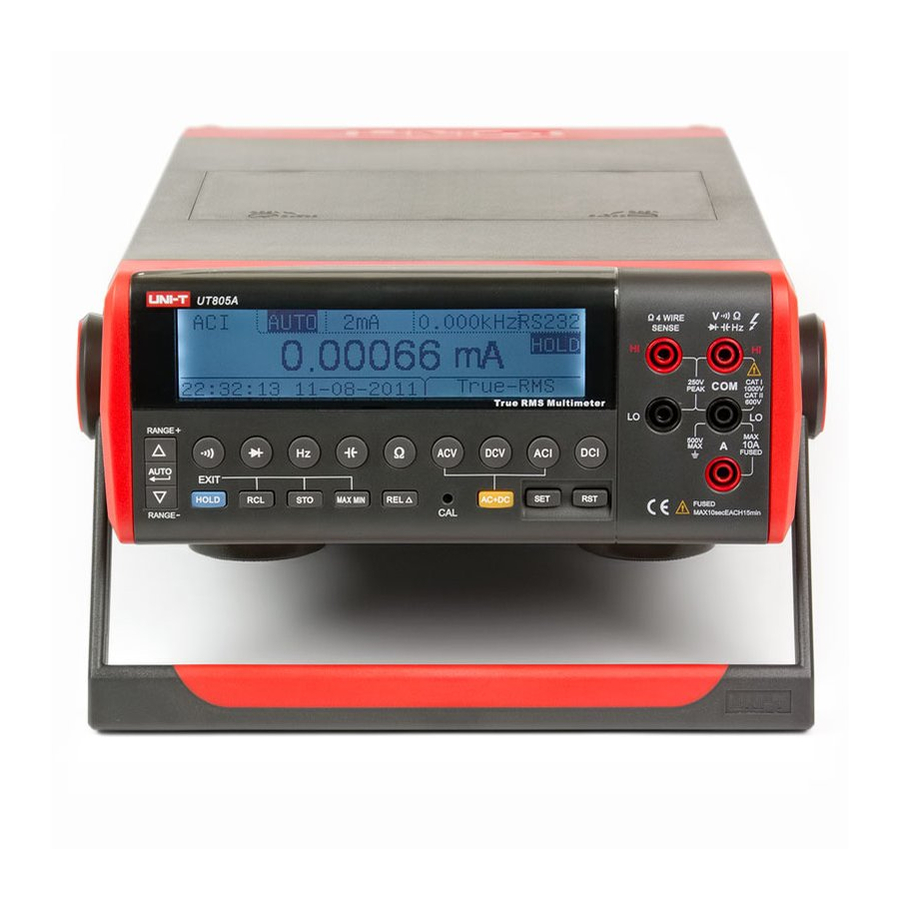
Model UT805: OPERATING MANUAL The Meter Structure A. Front Panel (see figure 1) VFD Display Primary Functional Buttons: Different key functions selection. COM Input Terminal: Negative input terminal, inserting the black test lead. V/ Input Terminal: Positive input terminal for voltage and resistance measurement, inserting the red test lead. - Page 11 Model UT805: OPERATING MANUAL CAL Button: Calibrate the accuracy of Voltage, Current and Resistance Secondary Functional Buttons: Different side functions selection. RANGE Button ( , AUTO and ): Select Auto or Manual ranging...
-
Page 12: Rear Panel
Model UT805: OPERATING MANUAL B. Rear Panel (see figure 2) HI Input Terminal: 4-wire configuration to measure resistance: high current terminal, inserting red test lead. LO Input Terminal 4-wire configuration to measure resistance: low current terminal, inserting black test lead. -
Page 13: Functional Buttons
Model UT805: OPERATING MANUAL Functional Buttons The pushbuttons on the front panel select the Meter functions and operations. Below table indicated for information about the functional button operations. Button Operation Performed Switching between auto and manual ranging, step through the ranges when the Meter is at manual , AUTO and ranging measurement mode. - Page 14 Model UT805: OPERATING MANUAL Button Operation Performed AC Current Measurement Press 2mA down to select 2mA current measurement range. 2mA & 200mA Press 200mA down to select 200mA current measurement range. Press both 2mA and 200mA down is a mis-operation, the Meter displays “ --Err 1-“.
- Page 15 Model UT805: OPERATING MANUAL Button Operation Performed MAX MIN Press MAX MIN to select the maximum and minimum value. STO and Press STO to store the reading. Press RCL to recall the stored reading. HOLD HOLD has two features: 1. Data Holding...
-
Page 16: Display Symbols
Model UT805: OPERATING MANUAL Display Symbols (see figure 3) HOLD AC+DC TrueRMS MAX MIN AVG mVAnF AUTO (figure 3) - Page 17 Model UT805: OPERATING MANUAL Number Symbol Meaning Indicator for high voltage Data hold is active HOLD Indicator for AC voltage or current Indicator for AC AC Voltage or Current with DC deviation measurement AC+DC Indicator for True RMS value of AC measurement...
- Page 18 Model UT805: OPERATING MANUAL Number Symbol Meaning The unit of frequency of AC measurement: Kilohertz (shown in the secondary display) The unit of capacitance nF : Nanofarad µF µF : Microfarad mF : Millifarad : Amperes (amps). The unit of current.
- Page 19 Model UT805: OPERATING MANUAL Number Symbol Meaning Relative mode is on The continuity buzzer is on. Larger digits Primary Display Indicates negative reading. Reading storage is on Reading recalling is on AUTO Auto ranging mode indicator...
-
Page 20: Measurement Operation
Model UT805: OPERATING MANUAL Measurement Operation If you have not done so, plug the line cord into the connector on the rear of the Meter. A. DC Voltage Measurement (See figure 4) Warning To avoid harms to you or damages to the Meter from... - Page 21 Model UT805: OPERATING MANUAL Connect the test leads across with the object being measured as shown in figure 4. The measured value shows on the primary display and the secondary display shows the measuring range. The sampling rate is around 2 times per second.
-
Page 22: Ac Voltage Measurement
Model UT805: OPERATING MANUAL B. AC Voltage Measurement (See figure 5) Warning To avoid harms to you or damages to the Meter from electric shock, please do not attempt to measure voltages higher than 1000V or 750V rms although readings may be obtained. - Page 23 Model UT805: OPERATING MANUAL Connect the test leads across with the object being When DC voltage measurement has been completed, disconnect the connection between the testing leads measured as shown in figure 5. The primary display and the circuit under test, and remove the testing shows the True RMS AC value, the effective reading leads away from the input terminals of the Meter.
-
Page 24: Dc Or Ac Current Measurement
Model UT805: OPERATING MANUAL C. DC or AC Current Measurement (see figure 6) Warning If the fuse burns out during measurement, the Meter may be damaged or the operator himself may be hurt. Use proper terminals, function, and range for the measurement. - Page 25 Model UT805: OPERATING MANUAL Note Press ACI or DCI button, then press 200mA button If the value of current to be measured is unknown, to select 200mA measurement range. Insert the red use the maximum measurement position, and reduce test lead into the 200mA MAX terminal and black the range step by step until a satisfactory reading is test lead into the COM terminal.
-
Page 26: Measuring Resistance
Model UT805: OPERATING MANUAL D. Measuring Resistance Warning To avoid damages to the Meter or to the devices under test, disconnect circuit power and discharge all the high-voltage capacitors before measuring resistance. To avoid harms to you, please do not attempt to input voltages higher than 60V DC or 30V AC. - Page 27 Model UT805: OPERATING MANUAL To obtain more accurate readings, you could short- circuit the test lead and press REL to display “0” before carrying out measurement Connect the test leads across with the object. The measured value shows on the primary display and the measuring range shows on the secondary display.
- Page 28 Model UT805: OPERATING MANUAL Note When measuring high resistance (>1M ), it is normal to take several seconds to obtain a stable reading. In order to obtain stable reading, choose shorter test lead to carrying out measurement. The LCD displays OL indicating open-circuit for the tested resistor or the resistor value is higher than the maximum range of the Meter.
-
Page 29: Testing Diodes
Model UT805: OPERATING MANUAL E. Testing Diodes (See figure 9) Warning To avoid possible damage to the Meter and to the device under test, disconnect circuit power and discharge all high-voltage capacitors before testing diodes. To avoid harms to you, please do not attempt to input voltages higher than 60V DC or 30V AC. - Page 30 Model UT805: OPERATING MANUAL on the component’s anode and place the black test lead on the component’s cathode. The measured value shows on the primary display and the secondary display shows 6.000V range. Note Connect the test leads to the proper terminals as said above to avoid error display.
-
Page 31: Testing For Continuity
Model UT805: OPERATING MANUAL F. Testing for Continuity (See figure 10) Warning To avoid damages to the Meter or to the devices under test, disconnect circuit power and discharge all the high-voltage capacitors before testing for continuity. To avoid harms to you, please do not attempt to input voltages higher than 60V DC or 30V AC. - Page 32 Model UT805: OPERATING MANUAL Note Open circuit voltage around 1.2V. The primary display shows OL indicating the tested circuit is open. When continuity testing has been completed, disconnect the connection between the testing leads and the circuit under test, and remove the testing...
-
Page 33: Capacitance Measurement
Model UT805: OPERATING MANUAL G. Capacitance Measurement (See figure 11) Warning To avoid damage to the Meter or to the equipment under test, disconnect circuit power and discharge all high-voltage capacitors before measuring capacitance. Use the DC Voltage function to confirm that the capacitor is discharged. - Page 34 Model UT805: OPERATING MANUAL The measured value shows on the primary display. The secondary display shows the measuring range Note If the tested capacitance has polarity, connect the red test lead to the capacitor’s positive and the black test lead to the capacitor’s negative.
-
Page 35: Frequency Measurement
Model UT805: OPERATING MANUAL H. Frequency Measurement (see figure 12) Warning To avoid harms to you, please do not attempt to input voltages higher than 60V DC or 30V AC. To measure frequency, connect the Meter as follows: Insert the red test lead into the terminal and the black test lead into the COM terminal. - Page 36 Model UT805: OPERATING MANUAL Note When making frequency measurement, it must comply with the following scope (a) requirement: When 10Hz ~ 1Mz : 150mV 30V rms. When > 1Mz~ 10MHz : 300mV 30V rms When > 10Mz~ 50MHz : 600mV 30V rms When >...
-
Page 37: Selecting A Measurement Range ( , Auto And Button)
Model UT805: OPERATING MANUAL Selecting a Measurement Range ( , AUTO and Button) ranging mode, or press to toggle in the manual ranging mode. The Meter is default at DC Voltage 2V auto ranging In the manual range mode, press to up measurement mode when turning on the Meter. -
Page 38: The Use Of Relative Value Mode
Model UT805: OPERATING MANUAL The Use of Relative Value Mode AUTO cannot be pressed, otherwise “--Err 1-“ will be displayed and then back to the current meaurement Relative Mode applies to all functions except continuity, range diode and frequency measurements. -
Page 39: Max Min Mode
Model UT805: OPERATING MANUAL MAX MIN Mode Selecting the MAX MIN mode turns off autoranging and locks in the present range. Make sure you are in the MAX MIN mode applies only to DCV, ACV, ACV and correct range before selecting the MAX MIN mode. If ACI with DC deviation, and resistance. -
Page 40: The Use Of Sto And Rcl Button
Model UT805: OPERATING MANUAL The Use of STO and RCL Button Follow the following procedure to recall the stored reading: STO Button 1. Press HOLD to exit STO mode. 2. Press RCL to step through MAX reading, MIN Press STO to step through 7 different storage speed... -
Page 41: Operation Of Hold Mode
Model UT805: OPERATING MANUAL Operation of Hold Mode General Specifications The Hold mode allows you to take a measurement and Maximum Voltage between any Terminals and hold that measurement on the display. This feature Grounding: can be particularly advantageous in difficult or hazardous Refer to different range input protection voltage. - Page 42 Model UT805: OPERATING MANUAL Icon Display: Safety/Compliances: Equipped with functions and electrical unit symbol IEC61010 CAT.I 1000V, CAT.II 600V overvoltage icon display. and double insulation standard. Polarity Display: Auto Certifications: Overloading Display: OL UL pending. Temperature: Operating: 0 C to +40...
-
Page 43: Accuracy Specifications
Relative humidity: not more than 75% RH. Temperature coefficient: 0.1 x (specified accuracy)/1 Note UT805 multimeter is a precise digital multimeter when you turn on the UT805 allow a warm-up period of at least 30 minutes for the internal components to stabilize this ensures that the multimeter accord with the specification A. -
Page 44: Ac Voltage
Model UT805: OPERATING MANUAL B. AC Voltage (True RMS) Accuracy Range Resolution 40Hz~10kHz >10~30kHz >30~50kHz >50~100kHz 200mV (0.1%+100) (0.2%+200) (0.3%+200) (0.5%+300) 10 V 100 V (1%+500) (2%+500) (0.2%+100) (0.3%+200) 200V 40Hz-1kHz: >1kHz-5kHz: 750V 10mV (0.3%+100) (0.4%+100) Remarks: Overload Protection: 1000V DC or 750V AC... -
Page 45: Dc Current
Model UT805: OPERATING MANUAL C. DC Current Range Measurement Scope Resolution Accuracy 0.01 A~2.20000mA 0.01 A (0.03%+10) 20mA 1 A~220.000mA 0.1mA~10.0000A 0.1mA (0.8%+60) Remarks: Overload Protection: At mA Range: Fuse 315mA, 250V, fast type, 5x20mm. At A Range :Fuse 10A, 250V, fast type, 5x20mm. -
Page 46: Ac Current
Model UT805: OPERATING MANUAL D. AC Current (Frequency range: 40Hz~5kHz) Range Measurement Scope Resolution Accuracy 0.01 A~2.20000mA 0.01 A (0.3%+100) 20mA 1 A~220.000mA 0.1mA~10.0000A 0.1mA (2%+200) Remarks: Overload Protection: At mA Range:Fuse 315mA, 250V, fast type, 5x20mm. At A Range :Fuse 10A, 250V, fast type, 5x20mm. -
Page 47: Resistance
Model UT805: OPERATING MANUAL E. Resistance Range Measurement Scope Resolution Accuracy 0.01 ~2.20000k 0.01 In REL mode: (0.01%+8) 0.1 ~22.0000k In REL mode: 200k 1 ~220.000k (0.01%+5) 10 ~2.20000M (0.02%+10) 100 ~22.0000M (0.1%+20) Remarks: Overload Protection : 1000V DC or 750V AC... -
Page 48: Diode Test
Model UT805: OPERATING MANUAL F. Diode Test Range Measurement Scope Resolution Overload Protection Remarks Open circuit voltage approximate 2.8V. 0.00~6.00V 10mV 250Vp A good silicon junction drops between 0.5V and 0.8V G. Continuity Test Range Measurement Scope Resolution Overload Protection Remarks Open circuit voltage approximate -1.2V. -
Page 49: Capacitance
Model UT805: OPERATING MANUAL H. Capacitance Range Measurement Scope Resolution Accuracy 1pF~5.999nF In REL mode: (2.5%+5) 60nF 10pF~59.99nF 10pF In REL mode: (2.0%+5) 600nF 100pF~599.9nF 100pF 1nF~5.999 F (2.0%+5) 60 F 10nF~59.99 F 10nF 600 F 100nF~599.9 F 100nF (5.0%+5) 1 F~5.999mF... -
Page 50: Frequency
Model UT805: OPERATING MANUAL I. Frequency Range Measurement Scope Resolution Accuracy 6kHz 1Hz~5.999kHz 60kHz 10Hz~59.99kHz 10Hz (0.1%+3) 600kHz 100Hz~599.9kHz 100Hz 6MHz 1kHz~5.999MHz 1kHz 60MHz 10kHz~59.99MHz 10kHz Remarks: Overload Protection: 250Vp Input scope (a): (DC electric level is zero) When 10Hz ~ 1MHz: 150mV 30V rms When >... -
Page 51: Calibration Procedure
Model UT805: OPERATING MANUAL CALIBRATION PROCEDURE Short circuit the test lead, press REL display “0”, input 19V, then press CAL The calibration must be done in manual ranging button. mode. The Meter displays: (--CAL--) (-HI-END) Power-up the Meter and allow it to stabilize for one (19.0000V), calibration finished. -
Page 52: Ac Voltage
Model UT805: OPERATING MANUAL B. AC Voltage(750V range: frequency 1kHz, all other 750V Input 190V, press CAL button to display ranges: frequency 20kHz) (-- CAL--) (-LO-END) ) Input 750V, press CAL button to display (-- CAL--) 200mV: Input 19mV, press CAL button to display (-HI-END) (750.00V), calibration... -
Page 53: Dc Current
Model UT805: OPERATING MANUAL C. DC Current (Calibrate both positive and negative D. AC Current (Frequency: 1kHz) polarity) Press REL to display “0”, input 1.9mA, Input 0.19mA, Press CAL button to display (--CAL--) (-LO-END) ) Input press CAL button to display (--CAL--) 1.9mA, Press CAL button to display (--CAL--) -
Page 54: Resistance
Model UT805: OPERATING MANUAL E. Resistance F. AC Voltage with DC deviation (AC+DC) Press REL to display “0”, input 1.9k , 1. Press ACV button press CAL button to display (--CAL--) 2. Press AC+DC button (-HI-END) ( 1.90000k ), calibration 3. -
Page 55: Summary Of Error Codes
Model UT805: OPERATING MANUAL SUMMARY OF ERROR CODES If the Meter is failed to operate properly, an error code is displayed in the primary display. Error codes are listed in below table: Error Code Description Err1 Wrong button is pressed Err2 At AVG mode, the number of average times >... -
Page 56: Maintenance
Model UT805: OPERATING MANUAL Maintenance A. General Service Calibrate the Meter around once a year to ensure the This section provides basic maintenance information accuracy of each functions. including general service and fuse replacement Periodically wipe the case with a damp cloth and mild instruction. -
Page 57: Replacing The Fuses
Model UT805: OPERATING MANUAL B. Replacing the Fuses (see figure 13) Warning To avoid electrical shock or arc blast, or personal injury or damage to the Meter, use specified fuses ONLY in accordance with the following procedure. To replace the Meter’s fuse: Turn the Meter off, disconnect the power cord and remove all connections from the terminals. - Page 58 Model UT805: OPERATING MANUAL the fuse from its bracket. Then install the replacement fuse. Install ONLY replacement fuses with the identical type and specification as follows and make sure the fuse is fixed firmly in the bracket. Fuse 1: 315mA, 250V, fast type, 5x20mm (AC220V)
-
Page 59: Rs232C And Usb Serial Port
RS232C and USB Serial Port System Requirements for Installing the UT805 Interface Program To use UT805 Interface Program, you need the following hardware and software: An IBM PC or equivalent computer with 80486 or higher processor and 600 x 800 pixel or better monitor. -
Page 60: Rs232C Serial Port
Model UT805: OPERATING MANUAL RS232C Serial Port A. Connecting between the Meter and computer (see figure 14) B. RS232C Port Cable The Meter Computer D-sub D-sub D-sub 9 Pin Male 9 Pin Female 25 Pin Female 2 (RXD) 3 (TXD) - Page 61 Model UT805: OPERATING MANUAL Serial port output 25 bits. Each bit is an alphabet, below table explains the meaning of each alphabet: Number S (STO) X (MAX) C (Continuity) E (REL) Start R (RCL) N (MIN) D (Diode) U (AUTO)
- Page 62 Model UT805: OPERATING MANUAL The Meter adopts a single large alphabet command, each command is sent out twice as below table: Number Command Meaning AC+DC Number Command Meaning HOLD When the Meter receives the computer sent command, same large alphabet command twice, it will return the same...
-
Page 63: Usb Serial Port
Panel => System => Device Manager. Make sure connect the Meter and the computer with the same TO COMPUTER port. Please refer to the included “Installation Guide & Computer Interface Software” for installing and (figure 15) operating instructions of the UT805 Interface Program. **END**... - Page 64 Model UT805: OPERATING MANUAL This operating manual is subject to change without notice. Copyright 2005 Uni-Trend International Limited. All rights reserved. Manufacturer: UNI-TREND TECHNOLOGY(DONG GUAN)LIMITED Address: Dong Fang Da Dao, Bei Shan Dong Fang Industrial Development District, Hu Men Town, Dong Guan City,...
Need help?
Do you have a question about the UT805 and is the answer not in the manual?
Questions and answers