Table of Contents
Advertisement
Advertisement
Table of Contents

Related Manuals for UNI-T UT81B


Summary of Contents for UNI-T UT81B
- Page 1 Model UT81B OPERATING MANUAL...
-
Page 2: Table Of Contents
Model UT81B: OPERATING MANUAL Table of Contents Chapter Title Page Before You Start Overview Unpacking Inspection Safety Information Rules For Safe Operation International Electrical Symbols Using The Testing Tool Reading the screen The Meter Structure Functional Buttons Making Measurements A. Scope Mode i. - Page 3 Model UT81B: OPERATING MANUAL Table of Contents Chapter Title Page vii. Measuring Capacitance Using Software Maintenance The Test Tool A. General Service B. Replacing the Fuses C. Replacing the Battery Specifications Safety and Compliances Physical Specifications General Specifications (Digital Multimeter) General Specifications (Scope) Feature Summary Basic Specifications (Digital Multimeter)
- Page 4 Model UT81B: OPERATING MANUAL Table of Contents Chapter Title Page H. Frequency and Duty Cycle % I. Capacitance...
- Page 5 Model UT81B: OPERATING MANUAL List of Tables Table Title Page Unpacking Inspection International Electrical Symbols Reading the Screen Functional Buttons...
- Page 6 Model UT81B: OPERATING MANUAL List of Tables Figure Title Page Meter Structure Functional Buttons Waveform Display Voltages Measurement A Range Measurement mA Range Measurement 10A Range Measurement Resistance Measurement Diode Test Continuity Test Frequency / Duty Cycle Measurement 3-10 Capacitance Measurement Fuse Replacement Battery Replacement...
-
Page 7: Before You Start
Model UT81B: OPERATING MANUAL Chapter 1 Before You Start Overview bandwidth 8MHz, real-time sample rate 40MS/s with This Operating Manual covers information on safety peak rate sampling process can catch up pulse industrial and cautions. Please read the relevant information signal. -
Page 8: Unpacking Inspection
Model UT81B: OPERATING MANUAL Unpacking Inspection Open the package case and take out the Meter. Check the items shown on Table 1-1 carefully to see any missing or damaged part: Table 1-1. Unpacking Inspection Item Description English Operating Manual 1 piece USB interface cable 1 piece CD-ROM (Installation Guide &... -
Page 9: Safety Information
Model UT81B: OPERATING MANUAL International electrical symbols used on the Meter and Safety Information in this Operating Manual are explained on page 10. This Meter complies with the standards IEC61010 safety measurement requirement: in pollution degree 2, Rules For Safe Operation overvoltage category (CAT. - Page 10 Model UT81B: OPERATING MANUAL connecting the Meter to the circuit. shock or damages to the Meter. Replace the battery as soon as the battery The rotary switch should be placed in the right position and no any changeover of range shall indicator appears.
-
Page 11: International Electrical Symbols
Model UT81B: OPERATING MANUAL International Electrical Symbols Symbols used on the Meter and in this manual are explained in Table1-2. Table 1-2. International Electrical Symbols AC or DC DC Measurement AC Measurement Continuity Test Diode Grounding Double Insulated Warning. Refer to the Operating Manual Deficiency of Built-In Battery Conforms to Standards of European Union... -
Page 12: Using The Testing Tool
Model UT81B: OPERATING MANUAL Chapter 2 Using the Testing Tool Reading the Screen The screen displays the menu that provides the following choices available: Table 2-1. Reading the Screen Table 2-1. Reading the Screen Display Description Display Description RANG Decrease a range Contrast The degree of contrast BASE... -
Page 13: The Meter Structure
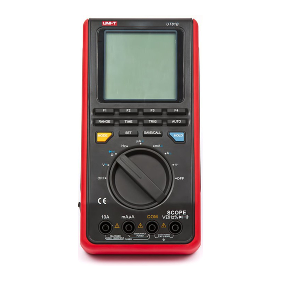
Model UT81B: OPERATING MANUAL The Meter Structure The Figure 2-1 shows the Meter structure. 1. USB Terminals 2. LCD Display 3. Functional Buttons 4. Rotary Switch 5. Power adaptor Input Terminals 6. 10A Input Terminal 7. mA A Input Terminals 8. -
Page 14: Functional Buttons
Model UT81B: OPERATING MANUAL Functional Buttons Table 2-2. Functional Buttons The buttons activate features that augment the function selected with the rotary switch. The buttons are shown Description Buttons in Table 2-2. Software functional buttons, details F1, F2, please refer to the below. F3 and F4 Under scope mode, Press Range Range... - Page 15 Model UT81B: OPERATING MANUAL Table 2-2. Functional Buttons Description Buttons To switch between waveform display Mode (scope mode) and digital reading (multimeter mode). This button is only valid when under voltage, frequency, currents mode. Press Set button to set the auto power off, backlight, contrast and beep Under scope mode, press Save/Cal to Save/Call...
-
Page 16: Making Measurements
Model UT81B: OPERATING MANUAL Chapter 3 Making Measurement Introduction Chapter 3 explains how to make measurements. Based on the working environment to set up sleep mode, contrast, beep You could turn the Meter off by turning to OFF position Press Set button to set the auto power off, display or set up the sleep mode from 1-30 minutes. - Page 17 Model UT81B: OPERATING MANUAL F2: Set the Display Backlight F4: Set the beeps features, it can only be used under BK Light ENTER resistance, diode and continuity measurement. Beep ENTER The brightness level from 0 to 31. Press F4 to confirm, save and return.
-
Page 18: Acv, Dcv, Hz, Acv And Dca Range
Model UT81B: OPERATING MANUAL Press Range to switch between DC and AC measurement. Turn the rotary switch to ACV, DCV, Hz, ACA or DCA When the frequency and amplitude of a waveform range, the Meter displays digital reading (Multimeter is unknown, press Auto : mode). - Page 19 Model UT81B: OPERATING MANUAL l Y-axis adjustment: Press Range button under scope increase the number of periods mode, the corresponding functional button: decrease the number of periods. Move Move Rang Rang trigger point move left trigger point right move move up the waveform The auto set feature will be off when changing the move down the waveform measurement mode.
-
Page 20: Trigger Function
Model UT81B: OPERATING MANUAL 10 location) F4: confirm Press Trig button under scope mode, the corresponding function buttons: When saving the data, it will overwrite the current Trig Trig Auto/Norm/Shot Slop Rrise/Fall data in the location no matter that location has data or not. -
Page 21: Digital Multimeter Mode
Model UT81B: OPERATING MANUAL B. Digital Multimeter Mode be returned to working mode to carry out measurement. Warning In order to have more accurate waveform, user can buy an optional BNC probe and scope probe to decrease To avoid harms to you or damages to the Meter signal attenuates. - Page 22 Model UT81B: OPERATING MANUAL When measuring voltage, the corresponding functional buttons AC / DC Rang Rang toggle between AC or DC relative mode (REL will be displayed at the right bottom of the LCD when it is on) select a range up select a range down Note: After changing the measurement mode, the...
-
Page 23: Measuring Currents
Model UT81B: OPERATING MANUAL Warning If the fuse burns out during measurement, the Meter may be damaged or the operator himself may be hurt. To avoid possible damage to the Meter or to the equipment under test, check the Meter’s fuses before measuring current. - Page 24 Model UT81B: OPERATING MANUAL 1. Insert the red test lead into the mA terminal and black test lead into the COM terminal. To measure AC A or DC A currents, set up the 2. Set the rotary switch to A . Meter as Figure 3-3 and proceed as follows: 3.
- Page 25 Model UT81B: OPERATING MANUAL 1. Insert the red test lead into the A mA terminal and black test lead into the COM terminal. To measure ACmA or DcmA currents, set up the 2. Set the rotary switch to mA . Meter as Figure 3-4 and proceed as follows: 3.
- Page 26 Model UT81B: OPERATING MANUAL 1. Insert the red test lead into the 10A terminal and black test lead into the COM terminal. To measure AC 10A or DC 10A currents, set up 2. Set the rotary switch to A the Meter as Figure 3-5 and proceed as follows: 3.
- Page 27 Model UT81B: OPERATING MANUAL When measuring current, the corresponding functional Note buttons: After changing the measurement mode, the AC / DC Rang Rang autoranging will be off automatically and the AUTO will be disappeared at the bottom left of the LCD. If the value to be measured is unknown, use the maximum measurement position and reduce the toggle between AC or DC...
-
Page 28: Measuring Resistance
Model UT81B: OPERATING MANUAL Warning To avoid possible damages to the Meter or to the devices under test, disconnect circuit power and discharge all the high-voltage capacitors before measuring resistance. To measure resistance, set up the Meter as shown in Figure 3-6 and follow the following procedure: Figure 3-6. - Page 29 Model UT81B: OPERATING MANUAL 1. Insert the red test lead into the terminal and the Note black test lead into the COM terminal. When measuring low resistance, the test leads can 2. Set the rotary switch to add 0.1 to 0.2 of error to resistance measurement. 3.
-
Page 30: Testing Diodes
Model UT81B: OPERATING MANUAL To test the diode out of a circuit, set up the Meter as Figure 3-7 and proceed as follows: Warning To avoid harms to you, please do not attempt to input voltages higher than 60V DC or 42V rms AC. To avoid damages to the Meter or to the devices under test, disconnect circuit power and discharge all the high-voltage capacitors before testing diodes. - Page 31 Model UT81B: OPERATING MANUAL 1. Insert the red test lead into the terminal and the Note black test lead into the COM terminal. Connect the test leads to the proper terminals as 2. Set the rotary switch to said above to avoid error display. 3.
-
Page 32: Testing For Continuity
Model UT81B: OPERATING MANUAL To test for continuity, set up the Meter as Figure 3-8 and do the following: Warning To avoid harms to you, please do not attempt to input voltage higher than 60V DC or 42V rms AC. To avoid possible damages to the Meter or to the devices under test, disconnect circuit power and discharge all the high-voltage capacitors before... - Page 33 Model UT81B: OPERATING MANUAL 1. Insert the red test lead into the W terminal and the Note black test lead into the COM terminal. When continuity testing has been completed, 2. Set the rotary switch to disconnect the connection between the testing leads 3.
- Page 34 Model UT81B: OPERATING MANUAL 1. Insert the red test lead into the Hz terminal and the black test lead into the COM terminal. Warning 2. Set the rotary switch to Hz. To avoid harms to you, please do not attempt to 3.
- Page 35 Model UT81B: OPERATING MANUAL Note The requirement of Input amplitude “a” is as follows: When 1MHz: 300 mV 30Vrms; 1MHz: 600 mV 5Vrms It is normal to have few seconds run time when switch from other functions to these functions. When Hz or duty cycle measurement has been completed, disconnect the connection between the testing leads and the circuit under test and remove...
-
Page 36: Measuring Capacitance
Model UT81B: OPERATING MANUAL To measure capacitance, set up the Meter as shown in Figure 3-10 and proceed as follows: Warning To ensure accuracy, the Meter inside is discharged against the tested capacitor To avoid damage to the Meter or to the equipment under test, disconnect circuit power and discharge all high-voltage capacitors before measuring capacitance. - Page 37 Model UT81B: OPERATING MANUAL Insert the red test lead into theterminal and the When measuring capacitance, the corresponding black test lead into the COM terminal. functional buttons: Set the rotary switch to measurement mode, the Capacity Meter may display a fixed reading which is a internal distributed capacitor value.
-
Page 38: Using Software
Model UT81B: OPERATING MANUAL Chapter 4 Using Software When using the Software, please refer to the Installation Guide of the included CD-ROM. -
Page 39: Maintenance The Test Tool
Model UT81B: OPERATING MANUAL Chapter 5 Maintaining The Test Tool This chapter provides basic maintenance information high temperature, explosive, inflammable and strong including battery and fuse replacement instruction. magnetic field. Warning Do not attempt to repair or service your Meter unless you are qualified to do so and have the relevant calibration, performance test, and service information. -
Page 40: Replacing The Fuses
Model UT81B: OPERATING MANUAL B. Replacing the Fuses Follow Figure 5-1 and proceed as follows to replace the Meter’s fuse: Turn the rotary switch to OFF and remove all connections from the terminals. Remove the screw from the battery compartment, and separate the battery compartment from the case bottom. -
Page 41: Replacing The Battery
Model UT81B: OPERATING MANUAL C. Replacing the Battery Warning To avoid false readings, which could lead to possible electric shock or personal injury, replace the battery as soon as the battery indicator “ ” appears. Make sure the test leads are disconnected from the circuit being tested before opening the case bottom. -
Page 42: Specifications
Model UT81B: OPERATING MANUAL Chapter 6 Specifications Safety and Compliances Refer to different range input protection voltage Maximum Voltage between any Terminal and Grounding Certification IEC 61010 CAT. II 1000V, CAT.III 600V overvoltage Compliances and double insulation standard 0.5A, 250V, fast type fuse, ø5×20mm Fused Protection for mA input terminal: 10A , 250V,fast type fuse, ø5×20mm Fused Protection for 10A input terminal:... -
Page 43: Physical Specifications
Model UT81B: OPERATING MANUAL Physical Specifications Digital: 3999 counts on display ; updates 2-3 times / second. Display (LCD) C~40 C (32 F~104 Operating Temperature C~50 C (14 F~122 Storage Temperature 75% @ 0 C~40 Relative Humidity 0% @ -10 C~50 Operating: 2000m;... -
Page 44: General Specifications (Digital Multimeter)
Model UT81B: OPERATING MANUAL General Specifications ( Digital Multimeter) When it is under Multimeter mode, you could select either auto or Range manual ranging. Auto, negative polarity displays “-“ Polarity Display OL Overloading Display Battery Deficiency General Specifications (Scope) 160 x 160 Monochrome Display Auto set the Meter according to the tested signal size Auto setting... -
Page 45: Feature Summary
Model UT81B: OPERATING MANUAL Feature Summary 160 x 160 Monochrome Display When it is under multimeter mode, the Meter automatically selects Autorange best range Beeper sounds for resistance readings below threshold. Continuity Measure signal on or off time in %. Duty Cycle Battery replaceable. -
Page 46: Basic Specifications (Scope)
Model UT81B: OPERATING MANUAL Basic Specifications (Scope) Horizontal Vertical Sampling rate 40M per second Bandwidth 8MHz Sampling rate / Scale 20 pixels Channel Single Updating rate >5 Coupling Trigger types Free Run / Normal / Voltage resolution 8 Bits Single Shot Timebase Range 100ns/div~5 sec /div Input Impedance... -
Page 47: Dc Voltage
Model UT81B: OPERATING MANUAL A. DC Voltage Range Resolution Accuracy Overload Protection Input Impedance 400mV 100 V Around 10M (0.8%+8) 1000V DC or AC 10mV (excluding waveform) 400V 100mV (0.1%+8) 1000V B. AC Voltage Range Resolution Accuracy Overload Protection Input Impedance 10mV Around 10M 1000V DC or AC... -
Page 48: Dc Current
Model UT81B: OPERATING MANUAL l The specification is same as Bi Under Multimeter mode. On the top right corner of the display shows the accuracy of the frequency which is around 2%. When the LCD displays 1-10 period waveform, the reading is valid, otherwise the Meter displays “ —— “ C. -
Page 49: Ac Current
Model UT81B: OPERATING MANUAL D. AC Current Range Resolution Accuracy Overload Protection 400 A 0.1 A (1.5%+8) 4000 A 0.5A, 250V, fast type fuse, ø5×20mm 40mA 10 A (2%+8) 400mA 100 A 10A, 250V, fast type fuse, ø5×20mm (2.5%+5) 10mA (Continuous measurement 10 seconds and interval more than 15 minutes.) Remarks:... -
Page 50: Resistance
Model UT81B: OPERATING MANUAL l The specification is same as Di Under Multimeter mode. On the top right corner of the display shows the accuracy of the frequency which is around 2%. When the LCD displays 1-10 period waveform, the reading is valid, otherwise the Meter displays “------ “ E. -
Page 51: Continuity Test
Model UT81B: OPERATING MANUAL G. Continuity Test Test Range Resolution Overload Protection Remarks l The buzzer sounds when the test resistance is 10 . 250V DC or AC l The buzzer does not sound when the test resistance is 100 . H. -
Page 52: I. Capacitance
Model UT81B: OPERATING MANUAL l The specification is same as Hi. Under Multimeter mode, press RANGE button to toggle between frequency and duty cycle mode. l On the top right corner of the display shows the waveform’s RMS value, for reference only. When the LCD displays 1-10 period waveform cycle or the peak-peak difference value is greater than 1/3 div, the reading is valid, otherwise the Meter displays “... - Page 53 Model UT81B: OPERATING MANUAL ** END ** This operating manual is subject to change without notice.
- Page 54 Model UT81B: OPERATING MANUAL Copyright 2006 Uni-Trend Group Limited. All rights reserved. Manufacturer: Uni-Trend Technology (Dongguan) Limited Dong Fang Da Dao Bei Shan Dong Fang Industrial Development District Hu Men Town, Dongguan City Guang Dong Province China Postal Code: 523 925 Headquarters: Uni-Trend Group Limited Rm901, 9/F, Nanyang Plaza...
- Page 55 Model UT81B: OPERATING MANUAL...
Need help?
Do you have a question about the UT81B and is the answer not in the manual?
Questions and answers