Advertisement
Table of Contents
- 1 Open Box Inspection
- 2 Safety Instructions
- 3 General Specifications
- 4 Display Screen
- 5 Symbols on Meter
- 6 DC Voltage Measurement
- 7 AC Voltage Measurement
- 8 Resistance Measurement
- 9 Continuity Measurement
- 10 Inductance Measurement
- 11 Capacitance Measurement
- 12 Frequency Measurement
- 13 Duty Ratio Measurement
- 14 Current Measurement
- 15 Technical Specifications
- Download this manual
Advertisement
Table of Contents

Related Manuals for UNI-T UT8803


Summary of Contents for UNI-T UT8803
- Page 1 Benchtop Digital Multimeter User Manual True RMS DIGITAL MULTIMETER 6000 Counts 1000V FUSED 750V CAT II 600V FUSED MAX 30 sec EACH 15min...
-
Page 2: Open Box Inspection
Warning: When the measured voltage is greater than 600V, The instrument cannot be used for measurements in CAT II, CAT III and CAT IV environment I. Introduction UT8803 is a professional 6000 count benchtop multimeter with high accuracy and outstanding performance. It supports multiple measurements: AC/DC voltage... -
Page 3: Safety Instructions
III. Safety instructions Safety standards This instrument strictly follows the EN 61010-1: 2010, EN 61326: 2013, RoHS, pollution grade II safety standard, CAT II 600V. Unplug the power cord when the instrument is not in use. Note: In the case that the instrument is not used in accordance with the operation instructions, the protection provided by the instrument may be weakened or lost. -
Page 4: General Specifications
8) Do not use or store the instrument in high temperature, high humidity, flammable, explosive or strong magnetic field environments. 9) Do not change the internal circuit of the instrument in order to avoid the damage to the instrument and users. -
Page 5: Display Screen
V.Display screen Capacitance Audion magnification Auto range Diode& thyristor polarity AUTO Manual range Thyristor/continuity/ RANGE Reading Maximum value Minimum value Unit Stimulation bargraph Data hold HOLD High voltage Relative value Inductance Series Capacitance loss factor, inductance Parallel D Q R quality factor, equivalent resistance USB connection measurement. - Page 6 Negative value Alternative current Direct current 15.Measurement units: mV、V Voltage μA、mA、A Current Ω、kΩ、MΩ Resistance nF、 F、mF μ Capacitance μH、mH、H Inductance Hz、kHz、MHz Frequency β Thyristor magnification ℃ / ℉ Temperature...
- Page 7 VI. Functions Input terminal Functions (measurement modes) Position ←→ DC voltage AC voltage V ←→ COM Ω V ←→ COM Resistance Continuity V ←→ COM Frequency/ duty ratio Hz % V ←→ COM Capacitance V ←→ COM V ←→ COM Inductance Capacitance loss factor V ←→...
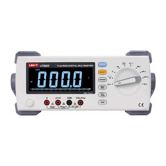
- Page 8 VII. Structure 1. Power switch True RMS DIGITAL MULTIMETER 2. Display screen 3. 20A jack 4. μA/mA jack 6000 Counts 5. COM jack 6. Function jack(voltage, resistance, inductance, 1000V 750V FUSED FUSED CAT II 600V MAX 30 sec EACH 15min capacitance, frequency, continuity, diode, duty ratio) 7.
-
Page 9: Symbols On Meter
Symbols on meter Power on Power off Direct current Alternating current Ground Terminal Caution, possibility of electric shock Warning or caution, To ensure safe operation and service of this meter, follow all warnings and instructions detailed in this manual. USB port Do not place equipment and its accessories in the trash. -
Page 10: Dc Voltage Measurement
VIII. Operation instructions Note: Select the corresponding input terminal. Functional dial should be switched to proper position 1. DC voltage measurement a) Insert red test lead to V jack, black lead to COM jack. b) Switch the dial to position, press button to enter DC measurement mode (figure 1). -
Page 11: Ac Voltage Measurement
2.AC voltage measurement a) Insert red test lead to V jack, black lead to COM jack. b) Switch the dial to position, press button to enter AC measurement mode (figure 1). Connect the test leads to the load in parallel. c) Reading displayed. -
Page 12: Resistance Measurement
3.Resistance measurement a) Insert red test lead to Ω jack, black lead to COM jack. b) Switch the dial to position, press button to enter resistance measurement mode (figure 2). Connect the test leads to the load in parallel. c) Reading displayed. d) Press button to manually switch the range. - Page 13 4.Diode measurement Method 1: a) Insert red test lead to jack, black lead to COM jack. b) Switch the dial to position, press button to enter diode measurement mode (figure 2). Connect the test leads to the load in parallel. When appears, positive pole: red test lead;...
-
Page 14: Continuity Measurement
5.Continuity measurement a) Insert red test lead to Ω jack, black to COM jack. b) Switch the dial to position, press to enter continuity measurement. Connect the test leads to the resistor in parallel. If circuit is well conducting, resistance<10Ω, buzzer goes off continuously; if circuit is open, resistance>50Ω, buzzer does not go off. -
Page 15: Inductance Measurement
6.Inductance measurement a) Insert red test lead to L jack, black test lead to COM jack. b) Switch the dial to L position, connect test leads with the inductance in parallel. c) Reading is displayed. d) Press to manually switch the range. e) Press to switch Q/R functions, long press this button to return to inductance measurement. -
Page 16: Capacitance Measurement
7.Capacitance measurement a) Insert red test lead to C jack, black test lead to COM jack. b) Switch the dial to ** position, connect test leads with capacitor in parallel. c) Reading is displayed, d) Press to manually switch the range. e) Press to switch Q/R functions, long press this button to return to capacitance measurement. - Page 17 8.Audion measurement a) Insert UT-S03A (multi-function socket) to the corresponding socket. b) Switch the dial to position, press to switch to audion measurement. c) Insert the audion to UT-S03A. Pins of audion should correspond with jacks of UT-S03A. B(basic), E(emission), C(collector) d) Reading is displayed.
- Page 18 9.Thyristor measurement a) Insert UT-S03A (multi-function socket) to the instrument. b) Switch the dial to position, press to switch to thyristor measurement. c) Insert SCR correctly to UT-S03A: G(gate), A(anode), K(cathode) d) Display as following: True RMS True RMS DIGITAL MULTIMETER DIGITAL MULTIMETER 6000 Counts 6000 Counts...
- Page 19 10.Temperature measurement a) Insert UT-S03A(multi-function socket) to the instrument. b) Switch the dial to position, press button to switch temperature unit. OL appears if no thermocouple connected. c) Insert the thermocouple to UT-S03A, pay attention to the polarity. (reverse polarity results in negative reading.) True RMS DIGITAL MULTIMETER...
-
Page 20: Frequency Measurement
11.Frequency measurement. a) Insert red test lead to Hz% jack, black to COM jack. b) Switch the dial to Hz% position, press to frequency measurement. c) Connect the test leads with frequency source in parallel. d) Reading is displayed. Note: Do not input over 30V AC or it will pose shock hazard. -
Page 21: Duty Ratio Measurement
Do not input over 36V AC or it will pose shock hazard. Disconnect test leads with the circuit after measurement. Duty ratio measurement function of UT8803 is only for reference. 13.Current measurement a) Insert red test lead to μA mA or A jack, black to COM jack. -
Page 22: Technical Specifications
IX. Technical specifications Accuracy: ± (% of reading + least significant digit), 1 year warranty Ambient temperature: 18˚C~28˚C Ambient humidity: ≤75% RH 1.DC voltage Range Accuracy Resolution 0.1mV ±(0.5%+2) 6000mV 10mV ±(0.3%+2) 100mV 600V ±(0.5%+3) 1000V Input impedance: 10MΩ; Maximum voltage:1000V... - Page 23 2.AC voltage Range Accuracy Resolution 40Hz-1kHz:±(0.6%+5) ≥1kHz-10kHz:±(1.2%+5) 600mV 0.1mV ≥10kHz-20kHz:±(3%+5) ≥20kHz-100kHz:±(4%+5) 40Hz-1kHz:±(0.6%+5) ≥1-10kHz: ±(1.2%+5) ≥10-20kHz: ±(3%+5) ≥20-100kHz: ±(4%+5) 40Hz-1kHz: ±(0.6%+5) ≥1-10kHz: ±(1.5%+5) 10mV ≥10-20kHz: ±(3%+5) ≥20-100kHz: ±(8%+5) 40 Hz-1kHz: ±(0.6%+5) 600V 100mV ≥1-10kHz: ±(3.5%+5) 40Hz-1kHz: ±(1.2%+5) 750V ≥1-3kHz: ±(3%+5) Input impedance: 10MΩ; Maximum voltage:750Vrms. Frequency response: 40Hz~100kHz.
- Page 24 3.DC current Range Accuracy Resolution 600μA 0.1μA ±(0.8%+3) 1μA 10μA 60mA ±(1.5%+3) 100μA 600mA ±(2%+5) 10mA If current ≥10A, measure time should be less than 30s with 15mins interval. In open status, allowable error: ≤5 residual digits. 4.AC current Range Accuracy Resolution 40Hz-10kHz ±(1%+5)
- Page 25 5. Resistance Range Accuracy Resolution 600Ω 0.1Ω ±(0.8%+5) 6kΩ 1Ω ±(1%+5) 60kΩ 10Ω 600kΩ 100Ω 6MΩ 1 Ω ±(2%+5) 60MΩ 10kΩ ±(5%+5) Open circuit voltage: -1.2V 6.Capacitance Range Accuracy Resolution ±(2.5%+5) 60nF 10PF ±(1.5%+5) 100pF 600nF 6µF ±(3%+10 ) 60 F µ...
- Page 26 7.Inductance Range Accuracy Resolution 600µH 0.1µH ±(2.5%+5) µ 10 H 60mH µ 100 H 600mH µ ±(2%+5 ) 10mH 100H 100mH Only for reference Measure voltage: 0.6V RMS Minimum measure range: >16μH Input impedance: 4KΩ 8.Equivalent resistance (ACR) Ω Range Accuracy Resolution 60Ω...
- Page 27 9.Frequency/ duty ratio Range Accuracy Resolution 600Hz 0.1Hz 6kHz 60kHz 10Hz ±(0.1%+10) 600kHz 100Hz 6MHz 1kHz 20MHz 10kHz Only for reference 5%~95% 0.10% Sensitivity: frequency<600KHz, amplitude>1.5Vrms or frequency>600kHz, amplitude>2.5Vrms, minimum input>5Hz. Duty ratio measurement only applicable for square wave ≤10kHz. 2Vpp≤input amplitude≤30Vpp Frequency≤1kHz, Duty: 5.0%~95.0% Frequency>1kHz, Duty: 30.0%~70.0%...
- Page 28 Display SCR polarity indicator SCR polarity Status Two-way 0.1V~2V Normal One-way 0.1V~2V Normal SCR bad contact Unknown SCR not connected or bad contact Unknown 11.Temperature Range Accuracy Resolution -40 -0 ℃ ℃ ±2%+5℃ >0 -400 ℃ ℃ ±1%+5℃ 1℃ >400 -1000 ℃...
- Page 29 X.Power supply and fuse replacement 1.Power supply setting 1) Turn the red switch to the corresponding position 2) Setting steps: a. Unplug the power cord b. Turn the red switch to corresponding position c. Selectable positions are shown below Voltage Description Position Demonstration...
Need help?
Do you have a question about the UT8803 and is the answer not in the manual?
Questions and answers