Table of Contents
Advertisement
Quick Links
Advertisement
Table of Contents

Related Manuals for Patton electronics 2029


Summary of Contents for Patton electronics 2029
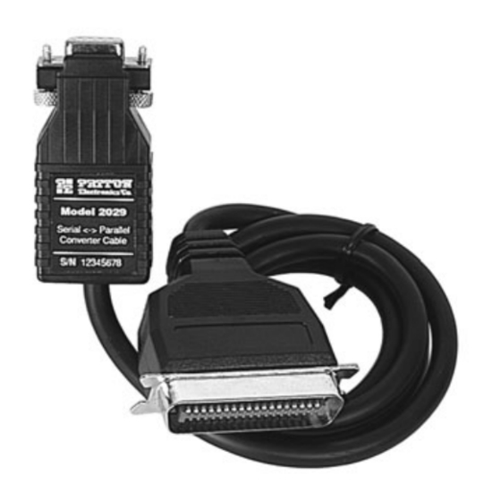
- Page 1 USER MANUAL MODEL 2029 Parallel to Serial/ Serial to Parallel Interface Converter SALES OFFICE Part #07M2029-B, Rev. C (301) 975-1000 Doc. #102011UB TECHNICAL SUPPORT Revised 6/16/09 C E R T I F I E D (301) 975-1007 An ISO-9001 http://www.patton.com...
-
Page 2: Radio And Tv Interference
However, there is no guarantee that interference will not occur in a particular installation. If the Model 2029 does cause interference to radio or television reception, which can be... - Page 3 NOTE: Packages received without an RMA number will not be accepted. Patton Electronics' technical staff is also available to answer any questions that might arise concerning the installation or use of your Model 2029. Technical Support hours: 8AM to 5PM EST, Monday through Friday.
-
Page 4: General Information
RS-232C serial data to parallel data format and vice versa. Incorporating advanced microprocessor technology, the Model 2029 is able to automatically sense and select parallel and serial modes. Requiring no AC power, the Model 2029 supports serial data rates to 38.4 Kbps. -
Page 5: Configuration Switches
Technical Support at (301) 975-1007. 3.1 CONFIGURATION SWITCHES The Model 2029 uses a set of eight external DIP switches (see Figure 1) that allow configuration to a wide range of applications. Because all eight switches are in one externally accessible DIP switch package, there is no need to open the case for configuration. -
Page 6: Detailed Switch Settings
DIP SWITCH SUMMARY TABLE Position Function Factory Default Flow Control Hardware Enabled LED Indicator Data, Parity, Stop Bits 8B, NP, 1S Data, Parity, Stop Bits Data, Parity, Stop Bits Data Rate 9600 bps Data Rate Data Rate 3.2 DETAILED SWITCH SETTINGS This section provides detailed information about the function of each DIP switch and lists all possible settings. - Page 7 Stop Data Parity Switches 6 through 8: Frequency and Data Rate Switches 6 through 8 determine the frequency and data rate. The following chart shows the settings that may be used: Model 2029 Data Rate 1200 2400 4800 9600 19200...
-
Page 8: Installation
4.0 INSTALLATION The Patton Model 2029 is very simple to install. Once you have configured the DIP switches, just plug it in like a normal cable and you're ready to go. Figure 3 illustrates the proper connections for the standard cables. If you have special-ordered a non-standard connector, your connections may be different. -
Page 9: Operation
“ON/OFF” switch. 5.1 LED STATUS MONITORS The Model 2029 features an easy-to-read status LED that glows red to indicate the condition of the transmission line. Figure 1 shows the location of the LED. The following chart describes the LED's various functions. - Page 10 APPENDIX A PATTON MODEL 2029 SPECIFICATIONS Interface: Asynchronous., RS-232C compatible Connectors: Serial, DB-9 female; Parallel, Centronics male Cables: Six foot integral cable Data Rates: 0- 38,400 Kbps LED: LED displays status and operating condition Power Supply: No external power required; uses power...
- Page 11 APPENDIX B PATTON MODEL 2029 INTERFACE CONNECTIONS Model 2029 Centronics Strobe (Output)-1 19-Ground Data bit 0 (I/O)-2 20-Ground Data bit 1 (I/O)-3 21-Ground Data bit 2 (I/O)-4 22-Ground Data bit 3 (I/O)-5 23-Ground Data bit 4 (I/O)-6 24-Ground Data bit 5 (I/O)-7...
- Page 12 APPENDIX C PATTON MODEL 2029 BLOCK DIAGRAM Copyright © Patton Electronics Company All Rights Reserved...