
Related Manuals for Patton electronics 2065RC


Summary of Contents for Patton electronics 2065RC
- Page 1 USER MANUAL MODEL 2065/66RC Miniature RS-232/V.35 to X.21 Interface Converter: Rack Mount Card SALES OFFICE Part# 07M2065/66RC-B (301) 975-1000 Doc# 077071UB TECHNICAL SUPPORT Revised 5/24/96 (301) 975-1007 http://www.patton.com...
- Page 2 Section 3.3 in this manual. • V.35 data rates up to 2.048 Mbps (Model 2066RC) • RS-232 data rates up to 128 kbps (Model 2065RC) • RS-232/V.35 interface is DTE/DCE switchable • Built-in 16 bit elastic buffers...
-
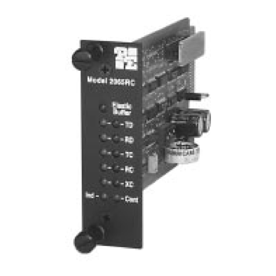
Page 3: Front Card Configuration
DTE). Clocking is supplied by the X.21 DCE device. This interface converter is available in two versions: The Model 2065RC converts from X.21 to RS-232, and supports sync data rates to DCE/DTE strap 128 kbps. The Model 2066RC converts from X.21 to V.35 and supports sync data rates to 2.048 Mbps. - Page 4 will change. The summary table below describes DIP switch S1 configured this way, the Model 2065/66RC will want to connect to an settings, including factory defaults. RS-232/V.35 DTE device. Changing the DCE/DTE strap orientation will enable the Model 2065/66RC to connect to an RS-232/V.35 DCE 3.1.2 SETTING THE DCE/DTE STRAP device.
- Page 5 4.0 INSTALLATION 3.3 REAR CARD CONFIGURATION This section describes the functions of the Model 1000R16P rack The rear interface card for the Model 2065/66RC is equipped with chassis, tells how to install front and rear Model 2065/66RC cards into two female UD-26 connectors: one for each port. This card has one the chassis and provides diagrams for wiring up the interface configuration jumper (JB4).
- Page 6 “A1” and “B1” (see figure 7, below). Port A1 connects to the 1000R16P is a "hot swappable" rack, it is not necessary for any cards RS-232 device (Model 2065RC) or the V.35 device (Model 2066RC). to be installed before switching on the power supply . The power supply Port B1 connects to the X.21 device in all cases.
-
Page 7: Operation
5.0 OPERATION If the DCE/DTE strap is set for “Converter = DTE”, then receive data is an input to the converter. Red indicates a mark or idle Once you have configured each Model 2065/66RC and connected state. Green indicates a space or active state. the cables, you are ready to operate the unit. - Page 8 2065-26M/25M ....Cable, 6 ft, UD-26M to DB-25M compatible 2065-26M/34F.....Cable, 6 ft, UD-26M to M/34F Data Rates: Model 2065RC (RS-232), up to 128 kbps; 2065-26M/34M ....Cable, 6 ft, UD-26M to M/34M Model 2066RC (V.35), up to 2.048 Mbps. Clocking: RS-232/V.35 DCE or DTE receiving timing 1000RPEM......120/240V Rear Power Entry Module...
- Page 9 3- (R-a) Receive (a) Sgnl Elmt Tmg (a) (S-a) -15 2- (T-a) Transmit (a) Transmit (b) (T-b) -14 1- (FG) Frame Ground MODEL 2065RC RS-232 INTERFACE Not Used -26 13- Not Used Not Used -25 12- Not Used External Clock (XC) -24...
Need help?
Do you have a question about the 2065RC and is the answer not in the manual?
Questions and answers