Table of Contents
Advertisement
Quick Links
Advertisement
Table of Contents

Related Manuals for Patton electronics 2085


Summary of Contents for Patton electronics 2085
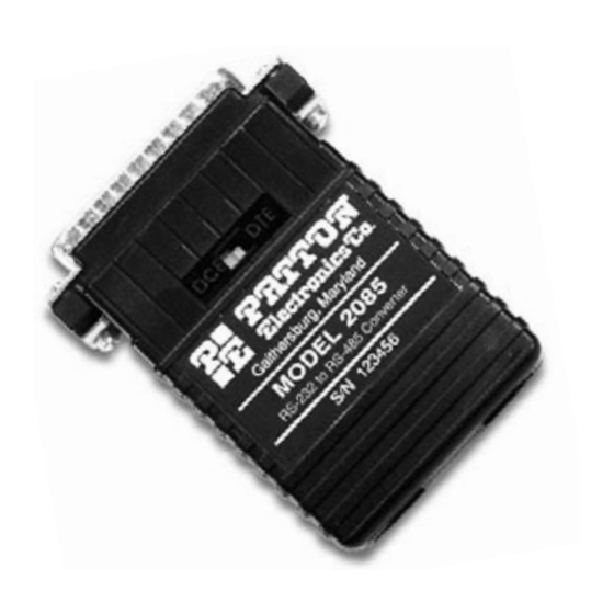
- Page 1 USER MANUAL MODEL 2085 High Speed RS-232 to RS-485 Interface Converter SALES OFFICE Part# 07M2085-D (301) 975-1000 Doc# 047033U, Rev. E TECHNICAL SUPPORT Revised 1/22/08 C E R T I F I E D (301) 975-1007 An ISO-9001 http://www.patton.com Certified Company...
-
Page 2: Radio And Tv Interference
However, there is no guarantee that interference will not occur in a particular installation. If the Model 2085 does cause interference to radio or television reception, which can be... - Page 3 Packages received without an RMA number will not be accepted. Patton Electronics’ technical staff is also available to answer any questions that might arise concerning the installation or use of your Model 2085. Technical Service hours: 8AM to 5PM EST, Monday through Friday.
-
Page 4: General Information
“echo”. RTS/CTS delay may be set for “no delay” or 8 mS. The Model 2085 is equipped with either male or female DB-25 for RS-232 connection. Options for twisted pair connection include terminal blocks with strain relief, RJ-11, RJ-45 and DB-25 male or female. - Page 5 Figure 1. Top view of Model 2085 board, showing DCE/DTE switch. Figure 2 (below) shows the location of the eight position DIP switch on the underside of the Model 2085 PC board. Figure 3 (following page) shows the orientation of the eight position DIP switch, with respect to ON/OFF positions.
-
Page 6: Dip Switch Configuration
For your convenience, the Model 2085 has an externally accessible DCE/DTE switch. If the device connected to the Model 2085 is a modem or multiplexer (or is wired like one), set the switch to “DTE”. This setting causes the Model 2085 to behave like Data Terminal Equipment and transmit data on pin 2. -
Page 7: Dip Switch Settings
Intermediate Impedance High Impedance S1-3: RTS/CTS Delay The setting for switch S1-3 determines the amount of delay between the time the Model 2085 “sees” RTS and when it sends CTS. Note: RTS/CTS Delay setting should be based upon transmission timing. S1-3... - Page 8 Low (120 Ohm) High (16 kOhm typical) S1-7 and S1-8: 2-Wire/4-Wire Modes Switches S1-7 and S1-8 are set together to determine whether the Model 2085 is in 2-wire or 4-wire operating mode. Note: 2-wire mode is half-duplex only. S1-7 S1-8...
-
Page 9: Configuration Switch Applications
3.4 CONFIGURATION SWITCH APPLICATIONS The switch settings generally needed to configure the Model 2085 for various applications are shown in the table below. Note: Do not change switch settings until you have carefully read Section 3.3. TYPICAL MODEL 2085 APPLICATIONS... -
Page 10: Installation
4.0 INSTALLATION Once you have properly set the configuration switches, you are ready to connect the Model 2085 to your system. This section tells you how to properly connect the Model 2085 to the RS-485 and RS-232 interfaces, and how to operate the Model 2085. - Page 11 In most modular RS-485 applications it is necessary to use a "cross over" cable. The diagram below shows how a cross over cable should be constructed for an environment where both the Model 2085 and the RS-485 device use a 6-wire RJ-11 connector. Similar logic should be followed when using RJ-45 connectors or a combination of the two.
- Page 12 4.1.3 4-WIRE CONNECTION USING TERMINAL BLOCKS If your RS-485 application requires you to connect two pairs of bare wires to the Model 2085, you will need to open the case to access the terminal blocks. The following instructions will tell you how to open the case, connect the bare wires to the terminal blocks, and fasten the strain relief collar in place so that the wires won't pull loose.
- Page 13 "G" on the terminal block. We recommend connecting the shield at the computer end only to avoid ground loops. A ground wire is not necessary for proper operation of the Model 2085. 7. When you finish connecting the wires to the terminal block, the assembly should resemble the diagram below: 8.
- Page 14 4.1.4 2-WIRE CONNECTION Most RS-485 devices employ a two-wire, half duplex configuration. When using this configuration, be sure to first set the Model 2085 to "two wire" mode—then use only the transmit (XMT) pair as shown on the following page.
-
Page 15: Star Topology
Call Technical Support for specific distance estimates. Figure 7 (below) shows how to wire the two-pair cables properly for a Model 2085 star topology. Note that the ground connection is not needed. HOST... -
Page 16: Daisy Chain Topology
DB-25 port of the RS-232 device. Remember to insert and tighten the two captive connector screws. (Note: If you must use a cable to connect the Model 2085 to the RS-232 device, make sure it is a straight through cable of the shortest possible length—we recommend 6 feet or less). - Page 17 APPENDIX A PATTON MODEL 2085 SPECIFICATIONS Transmission Format: Asynchronous Data Rate: Up to 115,200 bps Range: Up to 9 miles RS-232 Interface: DB-25, male or female (DCE/DTE switchable) RS-485 Interface Options: DB-25, male or female; RJ-11 or RJ-45 jack; terminal block with strain relief...
- Page 18 5- (CTS) Clear to Send To Model 2085 6- (DSR) Data Set Ready To Model 2085 7- (SG) Signal Ground From Model 2085 Data Term. Ready (DTR) - 20 8- (DCD) Data Carrier Detect To Model 2085 Copyright © Patton Electronics Company...
- Page 20 Dear Valued Customer, Thank you for purchasing Patton Electronics products! We do appreciate your business. I trust that you find this user manual helpful. We manufacture one of the widest selections of data communications products in the world including CSU/DSU's, network termination units, powered and self-powered short range modems, fiber optic modems, interface converters, baluns, electronic data switches, data-line surge protectors, multiplexers, transceivers, hubs, print servers and much more.