Table of Contents
Advertisement
SERVICE MANUAL
MODEL TYPE: YS1067
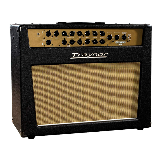
TRAYNOR YCS90
WEB ACCESS: http://www.yorkville.com
WORLD HEADQUARTERS
CANADA
U.S.A.
Yorkville Sound
Yorkville Sound Inc.
550 Granite Court
4625 Witmer Industrial Estate
Pickering, Ontario
Niagara Falls, New York
L1W-3Y8 CANADA
14305 USA
Voice: (905) 837-8481
Voice: (716) 297-2920
Fax: (905) 837-8746
Fax: (716) 297-3689
Quality and Innovation Since 1963
Printed in Canada
Manual-Service-YCS90-00-1v3.pdf
Advertisement
Table of Contents

Related Manuals for YORKVILLE Traynor YCS90


Summary of Contents for YORKVILLE Traynor YCS90
-
Page 1: Service Manual
SERVICE MANUAL MODEL TYPE: YS1067 TRAYNOR YCS90 WEB ACCESS: http://www.yorkville.com WORLD HEADQUARTERS CANADA U.S.A. Yorkville Sound Yorkville Sound Inc. 550 Granite Court 4625 Witmer Industrial Estate Pickering, Ontario Niagara Falls, New York L1W-3Y8 CANADA 14305 USA Voice: (905) 837-8481 Voice: (716) 297-2920... -
Page 2: Important Safety Instructions
IMPORTANT SAFETY INSTRUCTIONS This lightning flash with arrowhead symbol, within The exclamation point within an equilatereal triangle is an equilateral triangle, is intended to alert the user to intended to alert the user to the presence of important the presence of uninsulated “dangerous voltage” operating and maintenance (servicing) instructions in within the product’s enclosure that may be of sufficient the literature accompanying the appliance. -
Page 3: Specifications
Specifications Model: YCS50 / YCS50H / YCS90 Type: Combo / Head / Combo Guitar Amplifiers Cabinet Impedance (ohms): 8 / na / 8 Power @ min. impedance (Watts): 50 / 50 / 90 Minimum Impedance (ohms): 4 ohms on all models... - Page 4 MODEL TYPE: YS1064 MODEL TYPE: YS1067 Block Diagram for YCS50/50H/YCS90 YCS50H Tube Configuration D E S I G N E D A N D M A N U F A C T U R E D B Y Y O R K V I L L E S O U N D...
-
Page 5: Input Stage
Preamp Headers W20_:F 8 W20:F NET00142 NET00142 +200V Input Stage 113K INPUT_PL R7X1 3440 S8:C C21X W20_:A W25_ 100N 250V ALTERNATE EQ Shift INPUT_PL INPUT_PL INPUT INPUT CLN_GR W21_:C 8 STANDBY To_Input CLN_OUT_PL ALTERNATE EQ Shift EQ Shift ALTERNATE EQ Shift ALTERNATE To_Input 3700... - Page 6 +15V 100K 3700 K1:C 5908 1N5240BRL +15V 100N 10V0 BC550C 5101 TO92 1/4W 1/4W 1/4W 470K 470K 470K -15V 1/4W 100N FT.SWITCH 100R 4148 Gold Gold Gold 1/4W MPSA06 MPSA06 470K BC560C 4148 4148 4148 4148 1/4W BC550C LVGND 5103 5103 5102 TO92...
- Page 7 220P 100V 1/4W 620R 1/4W MINI 100V 220P R122 4423 1/4W P18:A 1/4W 5B LIN FX Ret 2 -15V 4417 1/4W P12:A Send Level U3:B 1/4W 620R U3:A U3:C MINI 1/4W 4423 TL072 1/4W 1/4W EFF.RETURN P13:A EFF.SEND FX Ret 1 1/4W TL072 +15V...
- Page 8 SEE PRODUCTION W26_ R257 W11_ 100N R108 NOTE, PC# 7446 113K C119 M1294 R256 R256 470K V200 M1294 V200 ONLY YCS90 (3/ ) 5 12V0 R109 R109 RING-SW R T V INT SPEAKER 12V0 C19X 470N R23X To_IG To_Preamp_2 R155 100K...
- Page 9 2. Lay C126 flat before RTVing. 3. Bend C21X as flat as possible towards components R210X and X34 before RTVing. PC# 7446 ONLY FOR YCS90 4. Wave solder in the indicated direction. 5. YCS90 ONLY T&R REMOVE R256 AND R257...
-
Page 10: Pin Configuration
CUT R91 CONNECTION AND RECONNECT IT TO W30 P4 BASS 4425 8431 2007/12/10 2.00 REVISED BOARD PER PC#7333 4423 8431 PC#7446, ONLY FOR YCS90, T&R WILL REMOVE TWO 2N5401 OD VOLUME 4425 8431 RESISTORS, R256 AND R257. Resonance 4425 8431... - Page 11 4520 160V 1/4W R259 820R 100U 1/4W 1N5237B 5108 4148 R260 TO92 1/4W Product Product YCS90 Output YCS90 Output Power Amp Power Amp PCB# PCB# M1296 M1296 Sheet Sheet Date: Date: Fri Jan 15, 2010 Fri Jan 15, 2010 Rev: Rev: YsType:.
- Page 12 3984 R139 2.0W 820R R137 R146 R T V 249K 249K 5834 R145 R154 2.0W 3984 R135 820R R T V R142 2.0W 3984 R T V 820R R138 249K R144 249K R143 R257 220K Bias 4148 2N5401 R260 R149 2.0W R T V 3984...
- Page 13 SEE LAYOUT DIAGRAM PRODUCTION NOTES M1296 MODEL(S):- YCS90 DATE VER# DESCRIPTION OF CHANGE 2007/06/06 1.00 FIRST DESIGN 1. APPLY RTV TO C64, C54, C66 AND C67. 12-FEB-2008 1.01 REVISION PER PC7456 09-JUN-2008 1.02 PC7393: CHANGE R49 FROM 39K TO 43K #4878...
-
Page 14: Variant Parts
Moved R171 0.05in away from tab W11. Rotate C8 to allow eyelet insertion. 19-JUN-2007 Added ClinchRepeats field -RAW R181 29-AUG-2007 2.00 Renamed to X8001. Added jumpers for M1295/YCS90, 220N 220N 1/4W C113 M1353/YCS50, M1357/YCS30. Imported fixture nodes. 250V 250V 4007... - Page 15 BREAK PANEL IN 2 ALONG THIS SCORE LINE BEFORE CLINCHING. CLINCH M1295 V05 YCS90 ORIGIN SCORE StepAndRepeat - X3@5.375Y2@5.400 SCORE R184 100R 100R 470U 1.0W 1.0W 1000U R T V R185 5618 100U 5635 8799 4007 5635 3692 R T V...
- Page 16 19-JUN-2007 Added ClinchRepeats field 3. B.A. WILL CUT TWO OTHER JUMPERS 29-AUG-2007 2.00 Renamed to X8001. Added jumpers for M1295/YCS90, TO220 M1353/YCS50, M1357/YCS30. Imported fixture nodes. M1295 YCS90 M1295 Moved R171 0.05in more away from tab W11. Updated...
-
Page 17: Amp Mode
M1295 V4.00 YCS90 100R 100R 470U R184 1.0W 1.0W 1000U R T V R185 8799 5618 100U 5635 3538 .4"Fins 5635 3692 4007 8799 R T V 3692 4007 To_PowerAmp R182 100U M1295 YCS90 HI V 16AWG M1353 YCS50/50H 5635... - Page 18 M1295 V4.00 YCS90 100R 100R 470U R184 1.0W 1.0W 1000U R T V R185 8799 5618 100U 5635 3538 .4"Fins 5635 3692 4007 8799 R T V 3692 4007 To_PowerAmp R182 100U M1295 YCS90 HI V 16AWG M1353 YCS50/50H 5635...
- Page 19 M1295 V4.00 YCS90 100R 100R 470U R184 1.0W 1.0W 1000U R T V R185 8799 5618 100U 5635 3538 .4"Fins 5635 3692 4007 8799 R T V 3692 4007 To_PowerAmp R182 100U M1295 YCS90 HI V 16AWG M1353 YCS50/50H 5635...
- Page 20 5B LIN 4417 Send Level 3424 DPDT SLID 4ohm/8ohm OD GAIN BOOST LEVEL OD VOLUME TREBLE BASS REVERB1 FX Ret 1 500K 500K 500K 100K 500K BOOST Modern Scoop 4425 4425 4425 4424 4423 4425 4423 4423 Alternate Alternate Alternate MASTER VOLUME Presence Resonance...
-
Page 21: Service Bulletin
SERVICE BULLETIN Tube Bias Adjustment 1. Adjust the amplifiers bias when in the 50W mode (YCS50/H) or 90W mode (YCS90). A speaker/load should be connected at all times when amplifier is powered. Products Affected Traynor YCS50, 2. Turn the amplifier on; allow it to warm up for 2-3 minutes. - Page 22 3428 8' 3/18 SJT AC LINE CORD REMOVABLE 8657 6-32 X 3/8" HEX SPACER ALUMINUM 5197 220P 100V 2%CAP T&R RAD CER.2NPO 8269 TRAYNOR LOGO PLASTIC W/ BLK INSERT 3865 1/2 PLASTIC HEX SPACER #6 5277 220P 200V 5%CAP T&R RAD CER.2NPO 8800 6-32 KEPS NUT ZINC 7083 12"...
Need help?
Do you have a question about the Traynor YCS90 and is the answer not in the manual?
Questions and answers