Advertisement
Quick Links
SERVICE MANUAL
YCV40/T
TYPE YS1003
WEB ACCESS: http://www.yorkville.com
WORLD HEADQUARTERS
CANADA
U.S.A.
Yorkville Sound
Yorkville Sound Inc.
550 Granite Court
4625 Witmer Industrial Estate
Pickering, Ontario
Niagara Falls, New York
L1W-3Y8 CANADA
14305 USA
Voice: (905) 837-8481
Voice: (716) 297-2920
Fax: (905) 837-8746
Fax: (716) 297-3689
Quality and Innovation Since 1963
Printed in Canada
Manual-Service-ycv40-ycv40t-00-2v9.pdf
Advertisement

Related Manuals for YORKVILLE YCV40


Summary of Contents for YORKVILLE YCV40
- Page 1 SERVICE MANUAL YCV40/T TYPE YS1003 WEB ACCESS: http://www.yorkville.com WORLD HEADQUARTERS CANADA U.S.A. Yorkville Sound Yorkville Sound Inc. 550 Granite Court 4625 Witmer Industrial Estate Pickering, Ontario Niagara Falls, New York L1W-3Y8 CANADA 14305 USA Voice: (905) 837-8481 Voice: (716) 297-2920...
-
Page 2: Important Safety Instructions
IMPORTANT SAFETY INSTRUCTIONS This lightning flash with arrowhead symbol, within The exclamation point within an equilatereal triangle is an equilateral triangle, is intended to alert the user to intended to alert the user to the presence of important the presence of uninsulated “dangerous voltage” operating and maintenance (servicing) instructions in within the product’s enclosure that may be of sufficient the literature accompanying the appliance. - Page 3 YCV40 Parts List 5/20/2010 YS No. Description Qty. YS No. Description Qty. 5906 RED 3MM LED 1V9 20MA.4SPCER T&R 2019 1/8W 100R0 1%FLAME PROOF T&R RES 5907 YEL 3MM LED 1V9 20MA.4SPCER T&R 4735 1.0W 100R T&R RES 5908 GRN 3MM LED 1V9 20MA.4SPCER T&R...
- Page 4 3438 IEC PWR SOC W/.205TAB &FUSE 10A250V 12AX7BLK 12AX7 DUAL TRIODE PREAMP TUBE 3552 NYLON SPRING CLAMP 6L6BULK 6L6G VACUUM TUBE BULK 3810 4" NYLON CABLE TIE CH1324 YCV40 POWER 120-100VAC 50-60HZ XFMR 3674 9 CIR CABLE HOLDER .098 CH1324M YCV40 O/P TRAN XFMR...
- Page 5 MODEL TYPE: YS1003 Block Diagram for YCV40 & YCV40T SPLITTER PREAMP D E S I G N E D A N D M A N U F A C T U R E D B Y Y O R K V I L L E S O U N D...
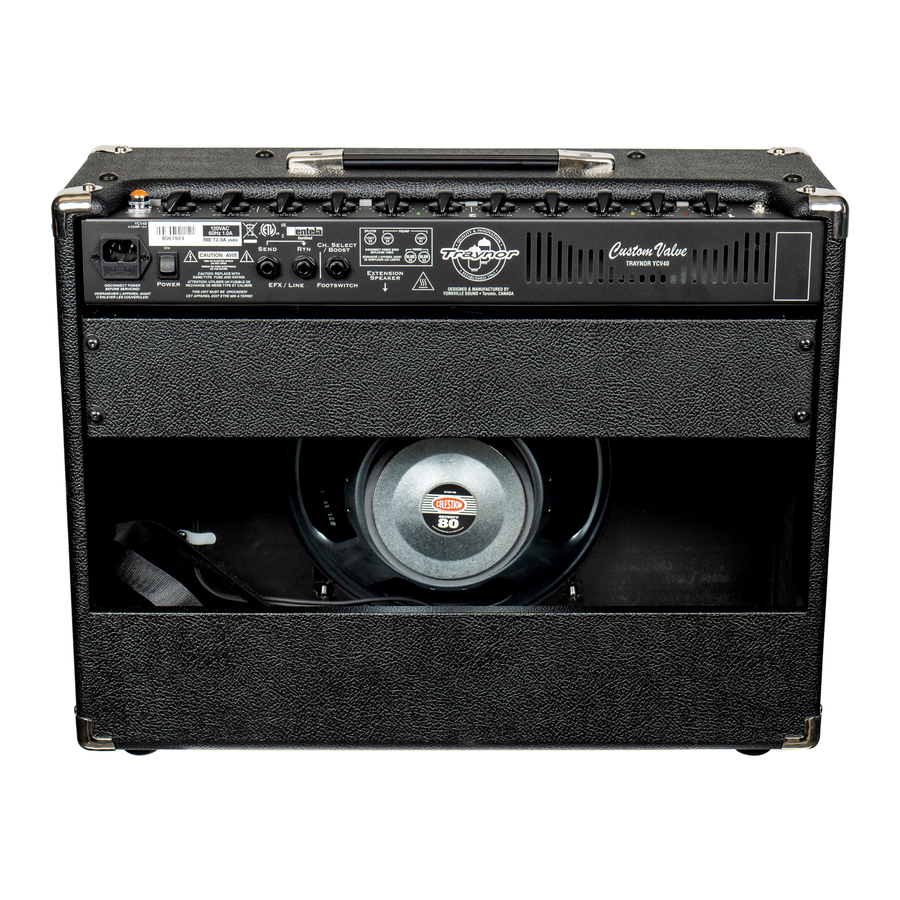
- Page 6 Description Labeled Components 8260 TRAYNOR LOGO 7080 12" 8R 80WPGM SPEAKER CELESTION 8461 TRIM CLIP (PLATED BLK ZINC) YCV40 GRILLE* ‡ Z357 3482 LOWPROFILE FUSEHOLDER 1/4" BUSSMANN 3438 AC RECEPTACLE / FUSE HOLDER 8456 10.0" STRAP HANDLE, NICKEL COVERS 3426...
- Page 7 Description Labeled Components 8260 TRAYNOR LOGO TUBE10 10" 8R 30WPGM SPEAKER CELESTION 8461 TRIM CLIP (PLATED BLK ZINC) YCV40 GRILL* Z357* 3438 AC RECEPTACLE / FUSE HOLDER 8456 10.0" STRAP HANDLE, NICKEL COVERS TFS-2B TRAYNOR DUAL FOOTSWCH 10' CORD 3537...
- Page 8 4423 1/4W P6:A 220K MINI Alternate 3700 3700 K1:A K2:A 1/4W This part is stuffed ONLY 113K 250V on M581 (YCV40) 3700 This part is stuffed ONLY 400V on M613 (YCV50BLUE) 100N 250V 470P 100V PRE-AMP 100K K1:B 4424 R114...
- Page 9 1/4W 1/4W REVERB SEND 250V 400V 100K NE5532N 6541 4424 U1:C 1/4W P11:A REVERB U1:B Product Product YCV40/YCV50BLUE YCV40/YCV50BLUE Loop/Reverb Loop/Reverb PCB# PCB# X8004 X8004 Sheet Sheet Date: Date: Wed Oct 08, 2008 Wed Oct 08, 2008 Rev: Rev: v14.00 v14.00...
- Page 10 These parts are X581 stuffed ONLY on 1/4W X581_ 220K MINI M581 (YCV40) These parts are X613 400V stuffed ONLY on X613_ M613 (YCV50BLUE) 1/4W 1/4W 1/4W 470K 270K 3682 SPLITTER OUTPUT 1324M OUTPUT V3:A V4:A 1.0W 3682 OUTPUT 100N...
- Page 11 4007 4007 IEC_RECT BC550C 3682 XF PRI 3682 R101 100R 100R 4007 1/4W 5101 TO92 {AWG} to_DC_FIL 3682 {AWG} DC_FIL YCV40 YCV50BLUE M581 M613 R106 R115 V4:B V3:C V5:B V1:C V2:C 5.0W 1/2W 1/2W PENTODE RefDes Value/YSpart# Value/YSpart# 2X_TRIODE_HCT PENTODE...
- Page 12 X8004 Version History M581 PCB HISTORY MODEL(S):- MODEL(S):- YCV40/YCV50BLUE YCV40 DATE VER# DESCRIPTION OF CHANGE DATE VER# DESCRIPTION OF CHANGE 23-APR-2008 14.00 Released for Production NOV/02/00 1.00 FIRST PRODUCTION PC7625,M581 R78 27K>18K#4831.M613 R78 18K>15K#4830 NOV/08/00 PC#6305 R63 2K2->3K3 R40 24K->27K...
- Page 13 SCORE Into Wave YCV40 M581 v14.00 BlankSize - 18600x12800 StepAndRepeat - X1@0.000Y2@6.400 BlankSize - 18600x12800 YCV40 M581 X581_ 5908 5907 100R0 5906 CHNL2 YCV50BLUE M613 CHNL1 100U BOOST v14.00 1 /5 4148 3700 100U CLEAN VOLUME TREBLE 500K 500K 100K...
- Page 14 SEE LAYOUT DIAGRAM YCV40 M581 v14.00 X8004 Version History X8004 DRILL HISTORY MODEL(S):- MODEL(S):- YCV40/YCV50BLUE YCV40/YCV50BLUE DATE VER# DESCRIPTION OF CHANGE DATE VER# DESCRIPTION OF CHANGE 23-APR-2008 14.00 Released for Production PC7625,M581 R78 27K>18K#4831.M613 R78 18K>15K#4830 PC7649, CHANGE P12 22K #4517 TO 10K #4520...
- Page 15 SEE LAYOUT DOCUMENTATION PRODUCTION NOTES 6. BEND C69 OVER Q7 AS FAR AS POSSIBLE BEFORE 1. RTV MUST BE ADDED TO THE FOLLOWING CAPS ADDING RTV C1,C16,C19,C17,C70 BETWEEN C84,C28,C60,C15 BETWEEN C49,C50, ADDED TO C15,C7,C8,C3,C9 7. PCBSA: BREAK OUT BOARD BEFORE TESTING C56,C14,C6,C10,C4,C2 AND C12 2.
- Page 16 ALUMINUM 2MM WITH_90DEG_BEND_UP_1.25" ALIGNMENT HOLE ALIGNMENT ADD 150K / 2watt resistor HOLE IRF830 7824 change to 1Kohm FUNCTION 24V_REG 100U change to 2.7ohms change to MPSA13 and be certain to re-orient the device as shown in purple remove R103 and replace with a 51v zener and a 390k resistor with R103 polarity as shown in purple.
- Page 17 YCV40 m581 Service Update for V11.00 boards April 2005 boards have been reworked as described in this document. To address PC#6866 a 22AWG wire, part # 3947 jumper, needs to be soldered from P11 to S3 on the bottom side of the board as shown:...
- Page 19 Standby Switch Fix...
- Page 22 R E D ME T A L _ B A C K T O E Y E 9 W C 1 1 GR AY G R A Y R E D WC 8 + 2 4 V B R O W N B R O W N S UPPLY E Y 9...
- Page 23 R E D M E T A L _ B A C K T O E Y E 9 W C 1 1 GR AY G R A Y R E D WC 8 + 2 4 V B R O W N B R O W N S UPPLY T O E Y 4...
Need help?
Do you have a question about the YCV40 and is the answer not in the manual?
Questions and answers