Vivotek VS8801 User Manual
Video server
Hide thumbs
Also See for VS8801:
- User manual (251 pages) ,
- Quick installation manual (10 pages) ,
- Specification (6 pages)
Table of Contents
Advertisement
Quick Links
Advertisement
Table of Contents

Related Manuals for Vivotek VS8801


Summary of Contents for Vivotek VS8801
- Page 1 Rev. 1.2...
-
Page 2: Table Of Contents
Ready to Use ....................13 Accessing the Video Server ..................14 Using Web Browsers ..................14 Using RTSP Players ..................16 Using 3GPP-compatible Mobile Devices ............17 Using VIVOTEK Recording Software ...............18 Main Page ........................19 Client settings ......................22 Configuration ......................25 System ......................26 Security ...................... - Page 3 VIVOTEK Technology License Notice ................177 Electromagnetic Compatibility (EMC) .............178 User's Manual - 3...
-
Page 4: Revision History
* Added Local Storage options. * Added the Quad View setting options. * Added the joystick configuration options. 3. Rev. 1.2: Added description for VS8801 stating that it does not support the SD card local storage. 4 - User's Manual... -
Page 5: Overview
The H.264 compression format drastically reduces the file sizes and conserves valuable bandwidth and storage space. The VS8401 supports simultaneous dual streams, while the VS8801 supports single stream to be transmitted in H.264, MPEG-4 and MJPEG formats for versatile applications. The stream can also be individually configured with frame rates, resolution, and image quality so as to meet different platforms or bandwidth constraints. -
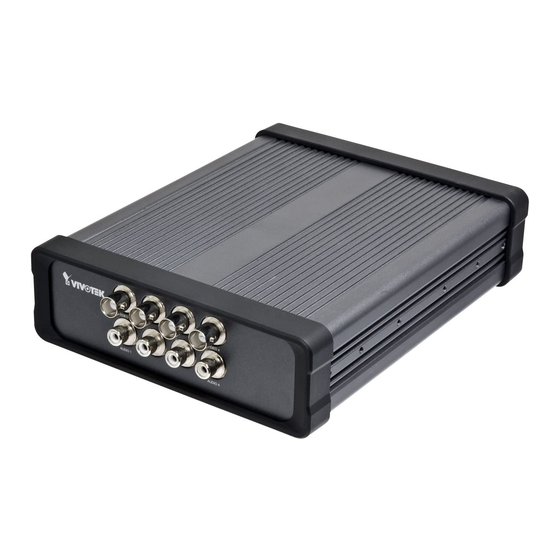
Page 6: Physical Description
VIVOTEK Physical Description Front Panel ■ VS8801 BNC Video Input RCA Audio Input ■ VS8401 USB & SD card USB function functions is not available are not available BNC Video Input on this unit. on this unit. RCA Audio Input Back Panel ■... - Page 7 VIVOTEK General I/O Terminal Block This video server provides a general I/O terminal block which is used to connect external input / output devices. The pin definitions are described below. ■ VS8801 USB & SD card USB function functions is not available are not available on this unit.
-
Page 8: Status Led
VIVOTEK DI/DO Diagram Please refer to the following illustration for the connection method. Sensors/detectors Digital Inputs Digital Outputs USB function is not available on this unit. Alarms DC Power Power Source NOTE: ► External alarms or other devices that connect to the digital outputs require external power supply, e.g., DC power from a power adapter. - Page 9 Blinking Red every 0.15 sec. + Blinking Green every Upgrading Firmware 1 sec. Blinking Red every 0.15 sec. + Blinking Green every Restoring default 0.15 sec. Hardware Reset ■ VS8801 USB & SD card USB function functions is not available are not available on this unit.
-
Page 10: Network Deployment
VIVOTEK Network Deployment Setting up the Video Server over the Internet This section explains how to configure the video server to an Internet connection. 1. Make video connection from the camera to the BNC video input. 2. Make audio connection from the Line-Out audio source to the RCA audio input. - Page 11 VIVOTEK Internet connection via a router Before setting up the video server over the Internet, make sure you have a router and follow the steps below. 1. Connect your video server behind a router, the Internet environment is illustrated below.
-
Page 12: Software Installation
After your network environment is analyzed, please click Next to continue the program. 3. The program will search for all VIVOTEK network devices on the same LAN. After a brief search, the main installer window will prompt. Double-click on the MAC and model name which matches the product label on your device to connect to the Network Camera via a web browser. -
Page 13: Ready To Use
VIVOTEK Ready to Use 1. A browser session with the Video Server should prompt as shown below. 2. You should be able to see live video from your camera. You may also install the 32-channel recording software from the software CD in a deployment consisting of multiple cameras. For its installation details, please refer to its related documents. -
Page 14: Accessing The Video Server
3. The live video will be displayed in your web browser. 4. If it is the first time installing the VIVOTEK video server, an information bar will pop up as shown below. Follow the instructions to install the required plug-ins on your computer. - Page 15 VIVOTEK ® 2. Look for Download signed ActiveX controls; select Enable or Prompt. Click OK. ® 3. Refresh your web browser, then install the Active X control. Follow the instructions to complete installation. User's Manual - 15...
-
Page 16: Using Rtsp Players
VIVOTEK Using RTSP Players To view the MPEG-4 streaming media using RTSP players, you can use one of the following players that support RTSP streaming. Quick Time Player Real Player VLC media player 1. Launch the RTSP player. mpegable Player 2. -
Page 17: Using 3Gpp-Compatible Mobile Devices
VIVOTEK Using 3GPP-compatible Mobile Devices To view the streaming media through 3GPP-compatible mobile devices, make sure the video server can be accessed over the Internet. For more information on how to set up the video server over the Internet, please refer to Setup the video server over the Internet on page 10. -
Page 18: Using Vivotek Recording Software
VIVOTEK Using VIVOTEK Recording Software The product software CD also contains recording software, allowing simultaneous monitoring and video recording for multiple video servers. Please install the recording software; then launch the program to add the video server to the Channel list. For detailed information about how to use the recording software, please refer to the user’s manual of the software or download it from... -
Page 19: Main Page
26. Camera Control Area Video Stream: VS8401 supports 4 channels for video live viewing, as VS8801 supports 8 channels. Each channel allows you to view only one stream. There are channel1,2,3,4,(5,6,7,8),and Quad View for you to choose. For more information about video settings, please refer to page 56 for detailed information. - Page 20 DI/O Control Area Digital output: There are 4 (VS8401) or 8 (VS8801) digital output switches; click to turn the digital output device on or off. Switch 1 is for channel 1 digital output control, switch 2 is for channel 2 digital output control, and so on.
- Page 21 VIVOTEK Title and Time: The video title and time can be stamped on the streaming video. For further configuration, please refer to Video settings on page 56. Video and Audio Control Buttons: Depending on the video server model and video server configuration, some buttons may not be available.
-
Page 22: Client Settings
VIVOTEK Client settings This chapter explains how to select the stream transmission mode and saving options on the local computer. When completed with the settings on this page, click Save on the page bottom to enable the settings. H.264 / MPEG-4 media options Select to stream video or audio data or both. - Page 23 VIVOTEK MP4 saving options Users can record live video as they are watching it by clicking Start MP4 Recording on the main page. Here, you can specify the storage destination and file name. Folder: Specify a storage destination for the recorded video files.
- Page 24 VIVOTEK Joystick settings Calibrate: Make sure a joystick is already attached to your COM port or USB port on your client computer. Click on the Calibrate button and the Windows Game Controller function will be started. If properly connected, your operating system should have already detected the joystick. Follow the onscreen instructions to calibrate your joystick.
-
Page 25: Configuration
Click Configuration on the main page to enter the camera setting pages. Note that only Administrators can access the configuration page. VIVOTEK offers an easy-to-use user interface that helps you set up your video server with minimal effort. To simplify the setting procedure, two types of user interfaces are available: Advanced Mode for professional users and Basic Mode for entry-level users. -
Page 26: System
VIVOTEK Advanced mode Configuration List Click to switch to Basic Mode Firmware Version Each function on the configuration list will be explained in the following sections. Those functions that are displayed only in Advanced Mode are marked with Advanced mode . If you want to set up advanced... - Page 27 VIVOTEK System time Keep current date and time: Select this option to preserve the current date and time of the Video server. The video server’s internal real-time clock maintains the date and time even when the power of the system is turned off.
-
Page 28: Security
VIVOTEK Security This section explains how to enable password protection and create multiple accounts. Root password The administrator account name is “root”, which is permanent and can not be deleted. If you want to add more accounts in the Manage User column, please apply the password for the “root” account first. -
Page 29: Https (Hypertext Transfer Protocol Over Ssl)
VIVOTEK HTTPS (Hypertext Transfer Protocol over SSL) Advanced Mode This section explains how to enable authentication and encrypted communication over SSL (Secure Socket Layer). It helps protect streaming data transmission over the Internet on higher security level. Enable HTTPS Check this item to enable HTTPS communication, then select a connection option: "HTTP & HTTPS"... - Page 30 VIVOTEK 4. The Certificate Information will automatically de displayed in the third column as shown below. You can click Property to view detailed information about the certificate. 5. Click Home to return to the main page. Change the address from “http://” to “https://“ in the address bar and press Enter on your keyboard.
- Page 31 VIVOTEK Create self-signed certificate manually 1. Select this option. 2. Click Create to open the Create Certificate page, then click Save to generate the certificate. 3. The Certificate Information will automatically be displayed in the third column as shown below. You can click Property to see detailed information about the certificate.
- Page 32 VIVOTEK 3. If you see the following Information bar, click OK and click on the Information bar at the top of the page to allow pop-ups. 4. The pop-up window shows an example of a certificate request. 32 - User's Manual...
- Page 33 VIVOTEK 5. Look for a trusted certificate authority that issues digital certificates. Enroll the video server. Wait for the certificate authority to issue a SSL certificate; click Browse... to search for the issued certificate, then click Upload in the second column.
-
Page 34: Snmp (Simple Network Management Protocol)
VIVOTEK SNMP (Simple Network Management Protocol) Advanced Mode This section explains how to use the SNMP on the video server. The Simple Network Management Protocol is an application layer protocol that facilitates the exchange of management information between network devices. It helps network administrators to remotely manage network devices and find, solve network problems with ease. -
Page 35: Network
Use fixed IP address: Select this option to manually assign a static IP address to the video server. 1. You can make use of VIVOTEK Installation Wizard 2 on the software CD to easily set up the Network Camera on LAN. Please refer to Software Installation on page 12 for details. - Page 36 VIVOTEK Primary DNS: The primary domain name server that translates hostnames into IP addresses. Secondary DNS: Secondary domain name server that backups the Primary DNS. Primary WINS server: The primary WINS server that maintains the database of computer name and IP address.
- Page 37 VIVOTEK NOTE: ► If the default ports are already used by other devices connected to the same router, the video server will select other ports for the video server. ► If UPnP is not supported by your router, you will see the following message: Error: Router does not support UPnP port forwarding.
- Page 38 VIVOTEK 4. In the Networking Services dialog box, select Universal Plug and Play and click OK. 5. Click Next in the following window. 6. Click Finish. UPnP is enabled. ► How does UPnP work? UPnP networking technology provides automatic IP configuration and dynamic discovery of devices added to a network.
- Page 39 VIVOTEK Enable IPv6 Select this option and click Save to enable IPv6 settings. Please note that this only works if your network environment and hardware equipment support IPv6. The ® browser should be Microsoft Internet Explorer 6.5, Mozilla Firefox 3.0 or above.
- Page 40 VIVOTEK Please follow the steps below to link to an IPv6 address: 1. Open your web browser. 2. Enter the link-global or link-local IPv6 address in the address bar of your web browser. 3. The format should be: http://[2001:0c08:2500:0002:0202:d1ff:fe04:65f4]/ IPv6 address 4.
- Page 41 Authentication server (usually a RADIUS server): Checks the client certificate and decides whether to accept the end user’s access request. ■ VIVOTEK video servers support two types of EAP methods to perform authentication: EAP-PEAP and EAP-TLS. Please follow the steps below to enable 802.1x settings: 1.
- Page 42 VIVOTEK 3. When all settings are complete, move the video server to the protected LAN by connecting it to an 802.1x enabled switch. The devices will then start the authentication automatically. NOTE: ► The authentication process for 802.1x: 1. The Certificate Authority (CA) provides the required signed certificates to the video server (the supplicant) and the RADIUS Server (the authentication server).
- Page 43 VIVOTEK QoS (Quality of Service) Advanced Mode Quality of Service refers to a resource reservation control mechanism, which guarantees a certain quality to different services on the network. Quality of service guarantees are important if the network capacity is insufficient, especially for real-time streaming multimedia applications. Quality can be defined as, for instance, a maintained level of bit rate, low latency, no packet dropping, etc.
- Page 44 VIVOTEK QoS/DSCP (the DiffServ model) DSCP-ECN defines QoS at Layer 3 (Network Layer). The Differentiated Services (DiffServ) model is based on packet marking and router queuing disciplines. The marking is done by adding a field to the IP header, called the DSCP (Differentiated Services Codepoint). This is a 6-bit field that provides 64 different class IDs.
- Page 45 Access name for channel 1~4/8: VS8401 supports 4 channels for video live viewing, as VS8801 supports 8 channels. Each channel allows you to view only one stream. The access name is used to differentiate the streaming source. Users can go to Configuration > Audio and video > Video settings to set up the video quality of linked streams.
- Page 46 VIVOTEK URL command -- http://<ip address>:<http port>/<access name for channel 1 ~ 4/8> For example, when the Access name for stream 2 is set to video2.mjpg: 1. Launch Mozilla Firefox or Netscape. 2. Type the above URL command in the address bar. Press Enter.
- Page 47 To stop talking, click again. The FTP server allows the user to save recorded video clips. You can utilize VIVOTEK's Installation Wizard 2 to upgrade the firmware via FTP server. By default, the FTP port is set to 21. It also can be assigned to another port number between 1025 and 65535.
- Page 48 Basic Digest Access name for channel 1 ~4/8: VS8401 supports 4 channels for video live viewing, as VS8801 supports 8 channels. Each channel allows you to view only one stream. The access name is used to differentiate the streaming source.
- Page 49 VIVOTEK RTSP port /RTP port for video, audio/ RTCP port for video, audio ■ RTSP (Real-Time Streaming Protocol) controls the delivery of streaming media. By default, the port number is set to 554. ■ The RTP (Real-time Transport Protocol) is used to deliver video and audio data to the clients. By default, the RTP port for video is set to 5556 and the RTP port for audio is set to 5558.
-
Page 50: Express Link
VIVOTEK Express link Express link is a free service provided by VIVOTEK server, which allows users to register an domain name for a network device. One URL can only be mapped to one Mac address. This service will check out if the host name is valid and automatically open a port on your router. -
Page 51: Ddns
DDNS: Dynamic domain name service Enable DDNS: Select this option to enable the DDNS setting. Provider: Select a DDNS provider from the provider drop-down list. VIVOTEK offers Safe100.net, a free dynamic domain name service, to VIVOTEK customers. It is recommended that you register Safe100.net to access VIVOTEK’s video servers from the Internet. - Page 52 4. Select Enable DDNS and click Save to enable the setting. ■ CustomSafe100 VIVOTEK offers documents to establish a CustomSafe100 DDNS server for distributors and system integrators. You can use CustomSafe100 to register a dynamic domain name if your distributor or system integrators offer such services.
-
Page 53: Access List
VIVOTEK Access list Advanced Mode This section explains how to control access permission by verifying the client PC’s IP address. General settings Maximum number of concurrent streaming connection(s) limited to: Simultaneous live viewing for 1~10 clients (including stream 1 and stream 2). The default value is 10. If you modify the value and click Save, all current connections will be disconnected and automatically attempt to re-link (IE Explore or Quick Time Player). - Page 54 VIVOTEK ■ Refresh: Click this button to refresh all current connections. ■ Add to deny list: You can select entries from the Connection Status list and add them to the Deny List to deny access. Please note that those checked connections will only be disconnected temporarily and will automatically try to re-link again (IE Explore or Quick Time Player).
-
Page 55: Digital I/O
VIVOTEK Digital I/O This section explains how to change digital input and digital output settings. Digital input settings You can select High or Low to define normal status for the digital input. The video server will report the current status. -
Page 56: Audio And Video
VIVOTEK Audio and video This section explains how to cofigure the audio and video settings of the video server. Overview This table shows all stream settings of each channel. Video settings Channel: In the drop-down list, there are channel 1~4/8, select one to set video settings on it in the column below. - Page 57 This function can work seamlessly with VIVOTEK’s ST7501 recording software. When an event occurs, the recording software can request time shift cache stream from the camera, which allows the user to retrieve pre-event video data.
- Page 58 VIVOTEK Advanced Mode Image settings Click Image Settings to open the Image Settings page. On this page, you can tune the White balance, Brightness, Saturation, Contrast, and Sharpness settings for the video. Please choose the Channel first. Image adjustment ■ Brightness: To adjust the image brightness level, please drag the slider bar to the right (+) to increase the effect, or to the left (-) to reduce the effect.
- Page 59 VIVOTEK ■ Enable deinterlace: Check to enable deinterlace, and choose Adaptive mode or Blend mode in the drop-down list. Adaptive mode provides the best image quality, while Blend mode provides better image quality (than not using the deinterlace function at all). Note that applying this function to all channels at the same time will consume quite a lot computing power.
- Page 60 VIVOTEK ■ To set the privacy mask windows, follow the steps below: 1. Click New to add a new window. 2. Use the mouse to size and drag-drop the window, which is recommended to be at least twice the size of the object (height and width) you want to cover.
- Page 61 VIVOTEK NOTE: ► Aspect ratio correction doesn’t support QCIF. ► When aspect ratio correction takes effect, the frame size for D1 will be adjusted to 640x480. This video server offers real-time H.264, MPEG-4, and MJPEG compression standards (Triple Codec) for real-time viewing.
- Page 62 VIVOTEK JPEG mode is selected, the video server continuously sends JPEG images to the client, producing a moving effect similar to a filmstrip. Every single JPEG image transmitted guarantees the same image quality, which in turn comes at the expense of variable bandwidth usage. Because the media contents are a combination of JPEG images, no audio data is transmitted to the client.
- Page 63 VIVOTEK ■ Available FPS Check Check frame rate to display the current available frame rate status (Available FPS). Available FPS provides the information of the unused encoding capability with available frame rate in different frame size. The embedded Soc (System-on-Chip) has limited encoding capability, so you may set the video quality according to the available FPS.
-
Page 64: Audio Settings
VIVOTEK the frame rate that cannot be reached is marked in red color. Audio settings Mute: Select this option to disable audio transmission from the video server to all clients. Note that if mute mode is turned on, no audio data will be transmitted even if audio transmission is enabled on the Client Settings page. -
Page 65: Motion Detection
VIVOTEK Motion detection This section explains how to configure the Video Server to enable motion detection. A total of three motion detection windows can be configured for each channel. Follow the steps below to enable motion detection: 1. Select Channel. - Page 66 VIVOTEK A green bar indicates that even though motions have been detected, the event has not been triggered because the image variations still fall under the defined threshold. Percentage = 30% This motion detection window will also be displayed on the Event Settings page. You can go to Application >...
-
Page 67: Camera Tampering Detection
VIVOTEK Percentage is a value that expresses the proportion of “alerted pixels” to all pixels in the motion detection window. In this case, 50% of pixels are identified as “alerted pixels”. When the percentage is set to 30%, the motions are judged to exceed the defined threshold; therefore, the motion window will be outlined in red. -
Page 68: Camera Control
Transparent HTTP Tunnel. The UART commands will be sent through HTTP tunnel established between the RS-485 device and the linked camera. For detailed application notes, please refer to URL Commands on page 105 or http://www.vivotek.com/downloadfiles/support/faq/172_document_2.pdf. 68 - User's Manual... - Page 69 VIVOTEK Preset positions If you select DynaDome/SmartDOME, Lilin PIH-7x00, or Pelco D, Pelco P protocol, Samsung scc643 protocol protocol as the PTZ driver and click the Save button, the Preset Position button will be enabled. Click Preset Position to open the settings page. You can also select preset positions for the camera to patrol.
- Page 70 VIVOTEK ■ Home location settings: You can configure the Home location by clicking on Set current position as home. Click on Restore home position to default, and the Home position will be set as the center position. ■ The Camera Control Panel and Preset positions will be displayed on the home page: ■...
- Page 71 VIVOTEK Camera ID settings VIVOTEK offers five PTZ drivers: DynaDome/SmartDOME, Lilin PIH-7x00, Pelco D protocol, Pelco P protocol, and Samsung scc643 protocol. If none of the above PTZ drivers is supported by your PTZ scanner, please select Custom camera (scanner). Please refer to the user’s manual of your PTZ scanner to determine the Camera ID, PTZ driver, and Port settings.
- Page 72 VIVOTEK Patrol settings You can select some preset positions for the Network Camera to patrol. Please follow the steps below to set up a patrol schedule: 1. Select Channel in the drop-down list. 2. Select the preset locations on the list, and click 3.
- Page 73 VIVOTEK Custom Command If Custom Camera (scanner) is selected as the PTZ driver, the Preset Position and PTZ Control Panel on the main page will be disabled. You will need to configure command buttons to control the PTZ scanner. Click Custom Command to open the Custom Command page to set the commands in the Control Settings session.
- Page 74 VIVOTEK ►The command buttons will be displayed on the main page: 74 - User's Manual...
-
Page 75: Homepage Layout
Theme Options (the third column on this page). The settings will be displayed automatically in this Preview field. The following shows the homepage using the default settings: ■ Hide Powered by VIVOTEK: If you check this item, it will be removed from the homepage. Logo Here you can change the logo at the top of your homepage. - Page 76 VIVOTEK Theme options Here you can change the color of your homepage layout. There are three types of preset patterns for you to choose from. The new layout will simultaneously appear in the Preview filed. Click Save to enable the settings.
- Page 77 VIVOTEK ■ Follow the steps below to set up the customed homepage: 1. Click Custom on the left column. 2. Click the field where you want to change the color on the right column. Color Selector Custom Pattern 3. The palette window will pop up as shown below.
-
Page 78: Application
Please note that there is a limited number of customized scripts you can upload; if the current amount of customized scripts has reached the limit, an alert message will pop up. If you need more information, please contact VIVOTEK’s technical support. 20110224... - Page 79 VIVOTEK Event settings In the Event settings column, click Add to open the Event settings page. On this page, you can arrange three elements -- Trigger, Schedule, and Action to set an event. A total of 3 event settings can be configured.
- Page 80 VIVOTEK ■ System boot This option triggers the video server when the power to the video server is disconnected. ■ Video motion detection This option makes use of the built-in motion detection mechanism as a trigger source. To enable this function, you need to configure a Motion Detection Window first.
- Page 81 VIVOTEK ■ Periodically This option allows the video server to trigger periodically for every other defined minute. Up to 999 minutes are allowed. ■ Digital input This option allows the video server to use an external digital input device or sensor as a trigger source.
- Page 82 VIVOTEK Action Define the actions to be performed by the video server when a trigger is activated. ■ Trigger digital output for seconds Check the desired DO to turn on the external digital output device when a trigger is activated. Specify the length (seconds) of the trigger interval in the text box.
- Page 83 VIVOTEK Here is an example of the Event settings page: When completed, click Save to enable the settings and click Close to exit Event Settings page. The new Event settings / Server settings / Media settings will appear in the event drop-down list on the Application page.
- Page 84 VIVOTEK Here is an example of the Application page with an event setting: When the Event Status is ON, once an event is triggered by motion detection, the video server will automatically send snapshots via e-mail. status or click Delete to remove...
-
Page 85: Server Settings
VIVOTEK Server settings Click Server on Event Settings page to open the Server Setting page. On this page, you can specify where the notification messages are sent when a trigger is activated. A total of 5 server settings can be configured. - Page 86 VIVOTEK FTP: Select to send the media files to an FTP server when a trigger is activated. ■ Server address: Enter the domain name or IP address of the FTP server. ■ Server port By default, the FTP server port is set to 21. It can also be assigned to another port number between 1025 and 65535.
- Page 87 VIVOTEK HTTP: Select to send the media files to an HTTP server when a trigger is activated. ■ URL: Enter the URL of the HTTP server. ■ User name: Enter the user name if necessary. ■ Password: Enter the password if necessary.
-
Page 88: Media Settings
VIVOTEK Media settings Click Media on the Event Settings page to open the Media Settings page. On this page, you can specify the type of media that will be sent when a trigger is activated. A total of 5 media settings can be configured. - Page 89 VIVOTEK Video clip: Select to send video clips when a trigger is activated. ■ Channel: The video source. The stream source will be identical to the preset time shift caching stream. For more information about time shift caching stream, please refer to page 57.
- Page 90 VIVOTEK You can continue to select a server and media type for the event. Please go back to page 79 for detailed information. ■ Enable customized folder: Create folders by date, time, and hour automatically: If you check this item, the system will generate folders automatically by date.
- Page 91 VIVOTEK Click 20110120 to open the directory: The format is: HH (24r) Click to open the file list for that hour 2011/01/20 2011/01/20 Click to go back to the previous Click to delete level of the directory selected items Click to delete all...
-
Page 92: Recording > Recording Settings
VIVOTEK Recording > Recording settings Advanced Mode This section explains how to configure the recording settings for the Video Server. Recording Settings Insert your SD card and click here to test (VS8401 only) NOTE: ► Please remember to format your SD card when using it for the first time. Please refer to page 109 for detailed information. - Page 93 VIVOTEK If you enalbe the adaptive recording and enable time-shift cache stream on Camera A, only when an event takes place on Camera A will the server records the streaming data at the full frame rate. This methodology only requires transferring the Intra frame data during normal operation, and full-frame-rate videos in the occurrences of events, and thus saving users of network bandwidth and storage space.
- Page 94 VIVOTEK Please follow steps 1 to 2 below to set up a recording setting: 1. Trigger Select a triggering condition: For example, event triggers might not make sense in a place full of human traffic during the office hours. You may want to enable the triggering conditions during the night.
- Page 95 VIVOTEK ■ Capacity: You can select either the entire storage space available or specify a reserved space. The recording size limit must be larger than the reserved space for cyclic recording. The reserved space is used for cyclic recording to prevent malfunctions that might occur during the transaction stage when the video feeds are about to fill up the storage space.
-
Page 96: Local Storage > Sd Card Management (For Vs8401 Only)
VIVOTEK Local storage > SD card management (for VS8401 only) This section explains how to manage the local storage on the Network Camera. Here you can view SD card status, and implement SD card control. SD card staus This column shows the status and reserved space of your SD card. Please remember to format the SD card when using for the first time. -
Page 97: Local Storage > Content Management
VIVOTEK Local storage > Content management This section explains how to manage the content of recorded videos on the Network Camera. Here you can search and view the records and view the searched results. Searching and Viewing the Records This column allows the user to set up search criteria for recorded data. If you do not select any criteria and click Search button, all recorded data will be listed in the Search Results cloumn. - Page 98 VIVOTEK ■ View: Click on a search result which will highlight the selected item in purple as shown above. Click the View button and a media window will pop up to play back the selected file. For example: Click to adjust the image size ■...
-
Page 99: System Log
VIVOTEK System log Advanced Mode This section explains how to configure the video server to send the system log to the remote server as backup. Remote log You can configure the video server to send the system log file to a remote server as a log backup. -
Page 100: View Parameters
VIVOTEK View parameters Advanced Mode The View Parameters page lists the entire system’s parameters in alphabetical order. If you need technical assistance, please provide the information listed on this page. 100 - User's Manual... -
Page 101: Maintenance
VIVOTEK Maintenance This chapter explains how to restore the video server to factory default, upgrade firmware version, etc. Reboot This feature allows you to reboot the video server, which takes about one minute to complete. When completed, the live video page will be displayed in your browser. The following message will be displayed during the reboot process. - Page 102 VIVOTEK Export / Upload Files Advanced Mode This feature allows you to Export / Upload daylight saving time rules, custom language files, and setting backup files. Export daylight saving time configuration file: Click to set the start and end time of DST.
- Page 103 Note: Do not power off the video server during the upgrade! Follow the steps below to upgrade the firmware: 1. Download the latest firmware file from the VIVOTEK website. The file is in .pkg file format. 2. Click Browse… and specify the firmware file.
- Page 104 VIVOTEK The following message is displayed when the upgrade has succeeded. Reboot system now!! This connection will close. The following message is displayed when you have selected an incorrect firmware file. Starting firmware upgrade... Do not power down the server during the upgrade.
-
Page 105: Appendix
VIVOTEK Appendix URL Commands for the Network Camera/Video Server 1. Overview For some customers who already have their own web site or web control application, the Network Camera/Video Server can be easily integrated through URL syntax. This section specifies the external HTTP-based application programming interface. - Page 106 VIVOTEK 106 - User's Manual...
- Page 107 VIVOTEK User's Manual - 107...
- Page 108 VIVOTEK 108 - User's Manual...
- Page 109 VIVOTEK User's Manual - 109...
- Page 110 VIVOTEK 110 - User's Manual...
- Page 111 VIVOTEK User's Manual - 111...
- Page 112 VIVOTEK 112 - User's Manual...
- Page 113 VIVOTEK User's Manual - 113...
- Page 114 VIVOTEK 114 - User's Manual...
- Page 115 VIVOTEK User's Manual - 115...
- Page 116 VIVOTEK 116 - User's Manual...
- Page 117 VIVOTEK User's Manual - 117...
- Page 118 VIVOTEK 118 - User's Manual...
- Page 119 VIVOTEK User's Manual - 119...
- Page 120 VIVOTEK 120 - User's Manual...
- Page 121 VIVOTEK User's Manual - 121...
- Page 122 VIVOTEK 122 - User's Manual...
- Page 123 VIVOTEK User's Manual - 123...
- Page 124 VIVOTEK 124 - User's Manual...
- Page 125 VIVOTEK User's Manual - 125...
- Page 126 VIVOTEK 126 - User's Manual...
- Page 127 VIVOTEK User's Manual - 127...
- Page 128 VIVOTEK 128 - User's Manual...
- Page 129 VIVOTEK User's Manual - 129...
- Page 130 VIVOTEK 130 - User's Manual...
- Page 131 VIVOTEK User's Manual - 131...
- Page 132 VIVOTEK 132 - User's Manual...
- Page 133 VIVOTEK User's Manual - 133...
- Page 134 VIVOTEK 134 - User's Manual...
- Page 135 VIVOTEK User's Manual - 135...
- Page 136 VIVOTEK 136 - User's Manual...
- Page 137 VIVOTEK User's Manual - 137...
- Page 138 VIVOTEK 138 - User's Manual...
- Page 139 VIVOTEK User's Manual - 139...
- Page 140 VIVOTEK 140 - User's Manual...
- Page 141 VIVOTEK User's Manual - 141...
- Page 142 VIVOTEK 142 - User's Manual...
- Page 143 VIVOTEK User's Manual - 143...
- Page 144 VIVOTEK 144 - User's Manual...
- Page 145 VIVOTEK User's Manual - 145...
- Page 146 VIVOTEK 146 - User's Manual...
- Page 147 VIVOTEK User's Manual - 147...
- Page 148 VIVOTEK 148 - User's Manual...
- Page 149 VIVOTEK User's Manual - 149...
- Page 150 VIVOTEK 150 - User's Manual...
- Page 151 VIVOTEK User's Manual - 151...
- Page 152 VIVOTEK 152 - User's Manual...
- Page 153 VIVOTEK User's Manual - 153...
- Page 154 VIVOTEK 154 - User's Manual...
- Page 155 VIVOTEK User's Manual - 155...
- Page 156 VIVOTEK 156 - User's Manual...
- Page 157 VIVOTEK User's Manual - 157...
- Page 158 VIVOTEK 158 - User's Manual...
- Page 159 VIVOTEK User's Manual - 159...
- Page 160 VIVOTEK 160 - User's Manual...
- Page 161 VIVOTEK User's Manual - 161...
- Page 162 VIVOTEK 162 - User's Manual...
- Page 163 VIVOTEK User's Manual - 163...
- Page 164 VIVOTEK 164 - User's Manual...
- Page 165 VIVOTEK User's Manual - 165...
- Page 166 VIVOTEK 166 - User's Manual...
- Page 167 VIVOTEK User's Manual - 167...
- Page 168 VIVOTEK 168 - User's Manual...
- Page 169 VIVOTEK User's Manual - 169...
- Page 170 VIVOTEK 170 - User's Manual...
- Page 171 VIVOTEK User's Manual - 171...
- Page 172 VIVOTEK 172 - User's Manual...
- Page 173 VIVOTEK User's Manual - 173...
- Page 174 VIVOTEK 174 - User's Manual...
- Page 175 VIVOTEK User's Manual - 175...
-
Page 176: Technical Specifications
12V 2A Remove 8 7 6 5 4 3 2 1 RESET Copyright 2011 VIVOTEK INC. All rights reserved. Distributed by: VIVOTEK INC. 6F, No.192, Lien-Cheng Rd., Chung-Ho, New Taipei City, 235, Taiwan, R.O.C. |T: +886-2-82455282| F: +886-2-82455532| E: sales@vivotek.com VIVOTEK USA, INC. -
Page 177: Technology License Notice
VIVOTEK Technology License Notice MPEG-4 AAC Technology THIS PRODUCT IS LICENSED UNDER THE MPEG-4 AAC AUDIO PATENT LICENSE. THIS PRODUCT MAY NOT BE DECOMPILED, REVERSE-ENGINEERED OR COPIED, EXCEPT WITH REGARD TO PC SOFTWARE, OF WHICH YOU MAY MAKE SINGLE COPIES FOR ARCHIVAL PURPOSES. FOR MORE INFORMATION, PLEASE REFER TO HTTP://WWW.VIALICENSING.COM. -
Page 178: Electromagnetic Compatibility (Emc)
があいます。この場合には使用者が適切な対策を講ずるよう要求されるこたがあります。 Liability VIVOTEK Inc. cannot be held responsible for any technical or typographical errors and reserves the right to make changes to the product and manuals without prior notice. VIVOTEK Inc. makes no warranty of any kind with regard to the material contained within this document, including, but not limited to, the implied warranties of merchantability and fitness for any particular purpose.
Need help?
Do you have a question about the VS8801 and is the answer not in the manual?
Questions and answers