Table of Contents
Advertisement
Quick Links
WT
WT-100
-100, WT
WT
WT
-100
-100
Universal Wireless Transmitters
1 1 1 1 . INTRODUCTION
. INTRODUCTION
. INTRODUCTION
. INTRODUCTION
The WT-100 and WT-100A are general purpose, battery powered single-input
transmitters for use with Normally Open (N.O.) and Normally Closed (N.C.) sensors
and inertial vibration detectors.
A reed switch built into both units can be used with a magnet (not supplied) to protect a
door or a window. An on-board tamper switch triggers a tamper alert (Channel 2) if the
front cover is removed from the base.
A special timing circuit saves the 9-volt battery power by limiting the transmitting time.
When the WT-100 is triggered, it transmits for about 2 seconds, then inhibits itself for
approximately one minute. If an input remains disturbed, the WT-100 will keep
transmitting signals for a 2-second duration each minute, until the input reverts to the
undisturbed state. The WT-100A is a single-shot (non-repeating) model that transmits
only once upon each input trigger.
The LED lights during the transmission period. A special circuit continuously monitors
the battery voltage. If this drops below about 7.5 Volts, the transmitter automatically
transmits a low battery alert signal for 1-2 seconds, to activate a buzzer in the target
receiver. Low battery signals are repeated at one-minute intervals for a few days,
depending on the remaining amount of battery energy. The LED lights during each
transmission, identifying the unit transmitting the low battery signal.
2 2 2 2 . SPECIFICATIONS
. SPECIFICATIONS
. SPECIFICATIONS
. SPECIFICATIONS
Frequency (MHz): 315, 404, 418, 433.92 or other frequencies
according to local requirements
System Code: 8-bit, 256 combinations, pulse width modulation
Channel Codes: 4 codes, DIP-switch selectable
Transmission Cycle: 2 seconds ON, 1 minute OFF, indicated by
LED.
Input Circuit: N.C. / N.O. (N.C. input must be shorted by the N.C.
jumper if not used).
Input Response: Adjustable, 5 to 30 ms
3 3 3 3 . INSTALLATION
. INSTALLATION
. INSTALLATION
. INSTALLATION
3.1 Mounting
Open the case by removing
the screw from the front cover.
Mount the base with the
printed circuit board in the
selected location, using the
mounting knockouts.
Be sure to mount the unit with the antenna wire hanging down.
Route the wiring through any wiring knockout in the base.
3.2 System Code Selection
The on-board CODE selector consists of an 8-position DIP switch
with keys marked from 1 to 8 (see Fig. 3). Each key is set to
either ON or OFF to create a unique digital code (256 possible
combinations). This code serves as a system code or a
password between the transmitter and the target receiver.
Select the desired system code
by shifting the keys with a ball-
point pen or a small screw-
driver. All wireless units used in
the system and the target
receiver must be programmed
with the same digital code.
Caution: The factory test code combination 2, 4, 5, 6, 7 ON /
1, 3, 8 OFF must not be used. Also avoid codes which are often
used: all keys ON, all keys OFF or alternating ON/OFF settings.
DE2001
, WT-100
-100A A A A
, WT
, WT
-100
-100
Figure 2. Front Cover Removal
Figure 3. Code Selector
Installation Instructions
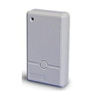
Figure 1. WT-100 and WT-100A
Power Supply: 9 VDC Alkaline or Lithium battery
Current Consumption: 10 µA standby, 10 mA in operation
Battery Supervision: Automatic transmission of low battery
alert code, which activates a buzzer in the receiver.
Compliance with Standards: Meets FCC Part 15, MPT 1349
and Directive 1999/5/EC.
Operating Temperature: 0°C to 49°C (32°F to 120°F).
Dimensions: 110 x 63 x 25 mm (4-5/16 x 2-1/2 x 1 in.).
Weight: 68 g (2.4 oz)
3.3 Channel Selection
Each transmitter can be set to transmit one of four different
"channel codes". The channel code is added to the system code
to activate a specific output in a multi-output receiver. Channel
codes are very useful for zoning purposes (activating various
types of zones of an alarm control panel).
The channel code selector consists of a 4-position DIP switch,
with keys marked from 1 to 4. The code is selected by switching
the corresponding key(s) to ON. You may select more than one
channel code for simultaneous activation of several channel
outputs at the receiver.
Note: Channel 2 code is transmitted automatically as a tamper
alert whenever the front cover is removed.
Setting all four-channel keys to
OFF will activate the buzzer at
the receiver (same as low
battery alert) and none of the
receiver's channel outputs.
3.4 Input Sensitivity Adjustment
Input sensitivity for vibration detectors is adjusted with the SENS.
potentiometer. The sensitivity is at maximum (response time
about 5 ms) with the control knob rotated fully towards [+] and at
minimum (response time about 30 ms) with the control knob
rotated fully towards [–]. If you are not using a vibration detector,
set the control fully towards [–].
Figure 4. Selecting Channel 2
1
Advertisement
Table of Contents

Related Manuals for Visonic WT-100


Summary of Contents for Visonic WT-100
-
Page 1: Installation Instructions
A special timing circuit saves the 9-volt battery power by limiting the transmitting time. When the WT-100 is triggered, it transmits for about 2 seconds, then inhibits itself for approximately one minute. If an input remains disturbed, the WT-100 will keep transmitting signals for a 2-second duration each minute, until the input reverts to the undisturbed state. -
Page 2: Battery Installation
VISONIC LTD. (ISRAEL): P.O.B 22020 TEL-AVIV 61220 ISRAEL. PHONE: (972-3) 645-6789, FAX: (972-3) 645-6788 VISONIC INC. (U.S.A.): 10 NORTHWOOD DRIVE, BLOOMFIELD CT. 06002-1911. PHONE: (860) 243-0833, (800) 223-0020 FAX: (860) 242-8094 VISONIC LTD. (UK): FRASER ROAD, PRIORY BUSINESS PARK, BEDFORD MK44 3WH. PHONE: (0870) 730-0800 FAX: (0870) 730-0801 www.visonic.com...
Need help?
Do you have a question about the WT-100 and is the answer not in the manual?
Questions and answers