Table of Contents
Advertisement
INSTALLATION AND TECHNICAL
REFERENCE MANUAL
WARNING! REMOTE START SYSTEMS ARE ONLY
APPLICABLE TO VEHICLES WITH AUTOMATIC
TRANSMISSION!
BOTH ORIGINAL KEYS ARE REQUIRED FOR ALL
REMOTE START SYSTEMS ON VEHICLES EQUIPPED
WITH SECURILOCK!
ALL MODELS 2002
Technical Support
(800) FORD-KEY
For French Technical Support
Rock Hebert (514) 973-2846
TOOLS REQUIRED
8mm
101871-2
2W7Z-16A901-AA
1/42
9/32"
7mm
1/4"
SK5W7J-19A361-AA
EXPERT FITMENT REQUIRED
Subject to Change Without Notice
Use Caution -
Personal Injury
Use Caution -
Vehicle Damage
See shop manual
!
Important note
© Copyright Ford 2005
SK5W7J-19A361-AA
Silicone sealer
D6AZ-19562-AA
Super Seal
F3AZ-19515-SA
Rev Date- 8/29/05
Advertisement
Table of Contents

Related Manuals for Ford SK5W7J-19A361-AA


Summary of Contents for Ford SK5W7J-19A361-AA
- Page 1 For French Technical Support Rock Hebert (514) 973-2846 TOOLS REQUIRED 9/32” 1/4” 101871-2 2W7Z-16A901-AA 1/42 SK5W7J-19A361-AA © Copyright Ford 2005 SK5W7J-19A361-AA EXPERT FITMENT REQUIRED Subject to Change Without Notice Use Caution - Personal Injury Use Caution - Vehicle Damage See shop manual...
-
Page 2: Table Of Contents
LOT MODE ONLY OPTION CHART ... 37 WIRING HARNESS LEGEND ... 38 CIRCUIT TESTING - IDENTIFYING CIRCUIT POLARITY ... 39 WIRE CONNECTION PROCEDURES ... 40 VEHICLE SPECIFIC WIRING DIAGRAMS ... 42 2W7Z-16A901-AA 2/42 SK5W7J-19A361-AA © Copyright Ford 2005 Rev Date- 8/29/05... -
Page 3: Read Me First
Then, when going through the installation print out the vehicle specific wiring section and use as a reference during the installation. 2W7Z-16A901-AA 3/42 buttons in the Acrobat toolbar, 2) clicking on the SK5W7J-19A361-AA © Copyright Ford 2005 Rev Date- 8/29/05... -
Page 4: Kit Contents
Ce véhicule est doté d'un démarreur à distance. Pour réduire les risques de blessures graves ou mortelles, mettre le démarreur à distance en mode service et débrancher la batterie du véhicule avant d'effectuer des travaux d'entretien sur celui-ci. © Copyright Ford 2005 Rev Date- 8/29/05... -
Page 5: Parts Bag Contents
PARTS BAG CONTENTS 750 OHM NOTE: Part bag contents are not available as service items 2W7Z-16A901-AA 5/42 1800 OHM SK5W7J-19A361-AA © Copyright Ford 2005 Rev Date- 8/29/05 PC-12 - 4X PC-32 - 7X... -
Page 6: Kit Bill Of Materials Lists
STATUS INDICATOR ASSEMBLY DIPOLE ANTENNA HOOD SAFETY SWITCH ASSEMBLY S - BB INSTALLATION PARTS BAG CC, DD FUSE PARTS BAG OPERATORS INSTRUCTION OPERATORS QUICK REFERENCE WALLET CARD UNDERHOOD WARNING LABEL 2W7Z-16A901-AA 6/42 SK5W7J-19A361-AA © Copyright Ford 2005 Rev Date- 8/29/05... - Page 7 STATUS INDICATOR ASSEMBLY DIPOLE ANTENNA 125 DB SIREN ASSEMBLY S - BB INSTALLATION PARTS BAG CC, DD FUSE PARTS BAG OPERATORS INSTRUCTION OPERATORS QUICK REFERENCE WALLET CARD VSS WINDOW WARNING DECAL 2W7Z-16A901-AA 7/42 SK5W7J-19A361-AA © Copyright Ford 2005 Rev Date- 8/29/05...
- Page 8 RKE DNA ASSEMBLY (2W7J-19A498-BA) 24-WAY WIRING HARNESS (BASE) STATUS INDICATOR ASSEMBLY WHIP ANTENNA S - BB INSTALLATION PARTS BAG CC, DD FUSE PARTS BAG OPERATORS INSTRUCTION OPERATORS QUICK REFERENCE WALLET CARD 2W7Z-16A901-AA 8/42 SK5W7J-19A361-AA © Copyright Ford 2005 Rev Date- 8/29/05...
-
Page 9: Module Preparation
(RKE, RKE/VSS or Preload), plug the whip antenna into the module at this time. 2W7Z-16A901-AA 9/42 DRIVER DOOR UNLOCK/ TRUNK RELEASE SK5W7J-19A361-AA © Copyright Ford 2005 DOME LIGHT PK LIGHTS DOOR LOCKS HVAC 1 MAIN B+ HVAC 2 IGNITION... - Page 10 Tape the harness sections together, making sure to cover all of the unused wires. 2W7Z-16A901-AA 10/42 Unused wires Driver kick panel harness Steering column harness 3” - 4” 2” - 3” SK5W7J-19A361-AA © Copyright Ford 2005 Rev Date- 8/29/05...
-
Page 11: Vehicle Preparation
If the doors do not unlock, connect the system’s factory alarm disarm output as shown in the vehicle specific wiring section or disable the door trim switch disable feature using the NGS or WDS testers. 2W7Z-16A901-AA 11/42 SK5W7J-19A361-AA © Copyright Ford 2005 Rev Date- 8/29/05... -
Page 12: Dipole Antenna Mounting
Also note that some interior trim fasteners are “one-time” use and must be replaced if removed. 2W7Z-16A901-AA 12/42 SK5W7J-19A361-AA © Copyright Ford 2005 NON-ELECTRONIC MIRROR Metal Film in windshield ELECTRONIC MIRROR Rev Date- 8/29/05... -
Page 13: Status Led
If necessary, remove the selected trim panel Insert status LED into drilled hole. The LED will plug into the main wiring harness during the wiring steps. Make sure to leave the LED pigtail accessible. SK5W7J-19A361-AA © Copyright Ford 2005 Rev Date- 8/29/05... -
Page 14: Securilock Interface Kits - 1L2Z-19G365-Ab & 1S4Z-19G365-Ab
5 minutes before proceeding with the next step. Remove backing from one side of supplied two-way tape ( E ) and apply tape around transceiver antenna coil. 2W7Z-16A901-AA 14/42 SECURILOCK KIT COMPONENTS SK5W7J-19A361-AA © Copyright Ford 2005 Rev Date- 8/29/05... - Page 15 Use a tie wrap ( Y ) to complete the bottom of the antenna loop as shown. Make sure that the Securilock PATS antenna loop ( B ) is as close to the PATS antenna as possible. INCORRECT 2W7Z-16A901-AA 15/42 SK5W7J-19A361-AA © Copyright Ford 2005 Stripe CORRECT Rev Date- 8/29/05...
- Page 16 Securilock Interface Module: 1) To or within 3” of a metal surface, including any underdash brackets, or 2) In the knee bolster area. Route the harness and connector ( C ) to module mounting location. 2W7Z-16A901-AA 16/42 SK5W7J-19A361-AA © Copyright Ford 2005 Vehicle wiring harness Rev Date- 8/29/05...
-
Page 17: Securilock Interface Kit - 1L3Z-19G365-Ab
2) In the knee bolster area. Route the harness and connector ( C ) to module mounting location. 2W7Z-16A901-AA 17/42 SECURILOCK KIT COMPONENTS SK5W7J-19A361-AA © Copyright Ford 2005 Vehicle wiring harness Rev Date- 8/29/05... -
Page 18: Siren Installation
Mount siren using screws provided (BB). Apply rustproofing compound (Super Seal #F3AZ-19515-SA) to drilled holes and mounting screws. Pass wires into vehicles interior compartment. Use silicone sealer (P/N D6AZ-19562-AA) as necessary to seal grommet. SK5W7J-19A361-AA © Copyright Ford 2005 Rev Date- 8/29/05... -
Page 19: Hood Tilt Switch Installation
The remaining hood switch wire will be connected during the wiring steps. Refer to the siren installation steps for directions on routing this wiring through the bulkhead panel. 2W7Z-16A901-AA 19/42 SK5W7J-19A361-AA © Copyright Ford 2005 10 in / lbs Rev Date- 8/29/05... -
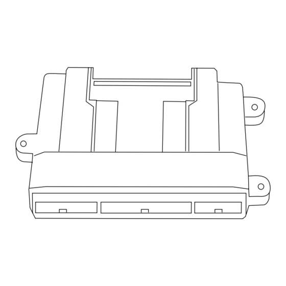
Page 20: Mounting The Control Module
(i.e. accelerator pedal, adjustable brake pedal assembly and/or parking brake mechanism). 2W7Z-16A901-AA 20/42 WHITE Main wire harness SK5W7J-19A361-AA Trim and tape off To Securilock module RF Antenna © Copyright Ford 2005 Rev Date- 8/29/05... -
Page 21: System Wiring Connections
RMST SYSTEMS ONLY - Install the Orange warning label on the radiator shroud (or similar area). 2W7Z-16A901-AA 21/42 VSS SYSTEMS ONLY - Install the window decals on both the driver and passenger side windows. SK5W7J-19A361-AA © Copyright Ford 2005 Rev Date- 8/29/05... -
Page 22: System Programming Instructions
4 times. 2W7Z-16A901-AA 22/42 on all, except RMST system which is SK5W7J-19A361-AA ) on the on the remote control transmitter to Press both buttons together 2 Button 4 Button Transmiter Transmitter © Copyright Ford 2005 Rev Date- 8/29/05... -
Page 23: Shock Sensor Setting
30 increments of the least sensative setting. Deviation from this setting recomendation introduces the potential of false alarm triggers, due to electrical or mechanical interference. 2W7Z-16A901-AA 23/42 SK5W7J-19A361-AA © Copyright Ford 2005 Rev Date- 8/29/05... -
Page 24: Tach (Idle Speed) Programming
Remove the second ignition key before engaging the remote starter. NOTE: If a third (or more) PATS ignition key has been programmed to the vehicle using either the Ford NGS or WDS programmers, the “Add Key” mode described in the installation manual may have been disabled. If this is the case, use the NGS or WDS programmer to either re- enable the “add key”... - Page 25 No remote start activation with the ignition key inserted into the ignition switch No remote start activation with the vehicle’s hood open No remote start activation with the vehicle’s brake pedal depressed 2W7Z-16A901-AA 25/42 SK5W7J-19A361-AA © Copyright Ford 2005 Rev Date- 8/29/05...
-
Page 26: Reference Section
1 relay D - Key latch release - 1 relay E- Door Lock/Unlock, A, E requires 2 relays for vehicles w/o factory RKE F- Remote Start Systems requires 2 relays B, F © Copyright Ford 2005 Rev Date- 8/29/05... - Page 27 2 relays for vehicles w/o factory RKE F- Remote Start Systems A, G requires 2 relays G- Tach Inverter required for vehicles with 6.0Liter diesel engines H- Parking lights, requires 2 relays © Copyright Ford 2005 Rev Date- 8/29/05...
- Page 28 C - Parking lights, requires 1 relay D- Door Lock/Unlock, requires 2 relays for vehicles w/o factory RKE E- Tach Inverter required for vehicles with 6.0Liter diesel engines F- Parking lights, requires 2 relays © Copyright Ford 2005 Rev Date- 8/29/05...
-
Page 29: Option Programming Charts
Delays crank attempt 30 seconds after ignition on..Off 6 – Rear Defrost output activation LED On- Activation only after remote start, LED Off- Activation anytime ... On 2W7Z-16A901-AA 29/42 SK5W7J-19A361-AA © Copyright Ford 2005 Factory setting Factory setting Factory setting Rev Date- 8/29/05... - Page 30 Switches Trunk release and Drivers door unlock outputs ... Off 6 – Learn tachometer With hood open or brake pedal pressed start engine. System will chirp horn every five seconds if a valid tach signal is present. 2W7Z-16A901-AA 30/42 SK5W7J-19A361-AA © Copyright Ford 2005 Rev Date- 8/29/05...
-
Page 31: Rke/Rmst Option Chart
Delays crank attempt 30 seconds after ignition on..Off 6 – Rear defrost output activation LED On-Activation after remote start, LED Off-Activation anytime ... On 2W7Z-16A901-AA 31/42 SK5W7J-19A361-AA © Copyright Ford 2005 Factory setting Factory setting Factory setting Rev Date- 8/29/05... - Page 32 Switches Trunk release and Drivers door unlock outputs ... Off 5 – Learn tachometer With hood open or brake pedal pressed start engine. System will chirp horn every five seconds if a valid tach signal is present. 2W7Z-16A901-AA 32/42 SK5W7J-19A361-AA © Copyright Ford 2005 Rev Date- 8/29/05...
-
Page 33: Rmst Option Chart
LED On – Positive, LED Off – Negative ... Off (Negative) 2 – Learn tachometer With hood open start engine. System will chirp horn every five seconds if a valid tach signal is present. 2W7Z-16A901-AA 33/42 SK5W7J-19A361-AA © Copyright Ford 2005 Factory setting Factory setting Rev Date- 8/29/05... -
Page 34: Deluxe Rke/Vss Option Chart
5 Second entry delay. Used for vehicles with external door mounted RKE keypads ... Off 4 – Use trunk relay as Driver door unlock Switches Trunk release and Drivers door unlock outputs ... Off 2W7Z-16A901-AA 34/42 SK5W7J-19A361-AA © Copyright Ford 2005 Factory setting Factory setting Factory setting Rev Date- 8/29/05... -
Page 35: Rke/Vss & Vss Option Chart
5 Second entry delay. Used for vehicles with external door mounted RKE keypads ... Off 4 – Use trunk relay as Driver door unlock Switches Trunk release and Drivers door unlock outputs ... Off 2W7Z-16A901-AA 35/42 SK5W7J-19A361-AA © Copyright Ford 2005 Factory setting Factory setting Factory setting Rev Date- 8/29/05... -
Page 36: Rke Option Chart
LED On – Positive, LED Off – Negative ... On (Positive) 2 – Use trunk relay as Driver door unlock Switches Trunk release and Drivers door unlock outputs ... Off 2W7Z-16A901-AA 36/42 SK5W7J-19A361-AA © Copyright Ford 2005 Factory setting Factory setting Factory setting Rev Date- 8/29/05... -
Page 37: Lot Mode Only Option Chart
With hood open or brake pedal pressed start engine. System will chirp horn every five seconds if a valid tach signal is present. 2W7Z-16A901-AA 37/42 SK5W7J-19A361-AA © Copyright Ford 2005 Factory setting Factory setting Factory setting Factory setting Rev Date- 8/29/05... -
Page 38: Wiring Harness Legend
Trunk Ajar Input TAN/RED Trunk Release/Driver Door Unlock Switch Input RED/WHITE Headlight Output / AUX 1 BLUE/WHITE Rear Defroster Output / AUX 2 GREEN/WHITE Memory 1 Output YELLOW/GREEN Memory 2 Output Open Open Open © Copyright Ford 2005 Rev Date- 8/29/05... -
Page 39: Circuit Testing - Identifying Circuit Polarity
(1) volt. However, when actuated the observed voltage will be 0V or very close to it. 2W7Z-16A901-AA 39/42 POSITIVE POLARITY CIRCUIT SK5W7J-19A361-AA © Copyright Ford 2005 DC Volts NEGATIVE POLARITY CIRCUIT Rev Date- 8/29/05... -
Page 40: Wire Connection Procedures
DO NOT USE CRIMP-CONNECTORS OF ANY KIND. THEY ARE NOT A ROBUST METHOD FOR SPLICING IN NEW WIRES. 2W7Z-16A901-AA 40/42 Wire From Powercode Harness Cut Target Wire In Vehicle SK5W7J-19A361-AA © Copyright Ford 2005 Heat Shrint Tubing Wih Hot Melt Wax Rev Date- 8/29/05... - Page 41 SOLDER MUST BE ROSIN CORE MILDLY ACTIVATED (RMA). DO NOT USE ACID CORE SOLDER. DO NOT USE CRIMP-CONNECTORS OF ANY KIND. THEY ARE NOT A ROBUST METHOD FOR SPLICING IN NEW WIRES. 2W7Z-16A901-AA 41/42 Wire From Powercode Harness SK5W7J-19A361-AA © Copyright Ford 2005 Heat Shrink Tubing With Hot Melt Wax Rev Date- 8/29/05...
-
Page 42: Vehicle Specific Wiring Diagrams
MAKE THIS CONNECTION FIRST! Box 5 Optional Installation Feature See Optional connections page Cut and tape off if not used SK5W7J-19A361-AA © Copyright Ford 2005 SK5W7J-19A361-AA (indicates CHASSIS GROUND POINT IN DRIVERS KICK PANEL Dome Light (BLACK/BLUE) + HARNESS UNDER...
Need help?
Do you have a question about the SK5W7J-19A361-AA and is the answer not in the manual?
Questions and answers