
Related Manuals for Asante 10T Hub/8


Summary of Contents for Asante 10T Hub/8
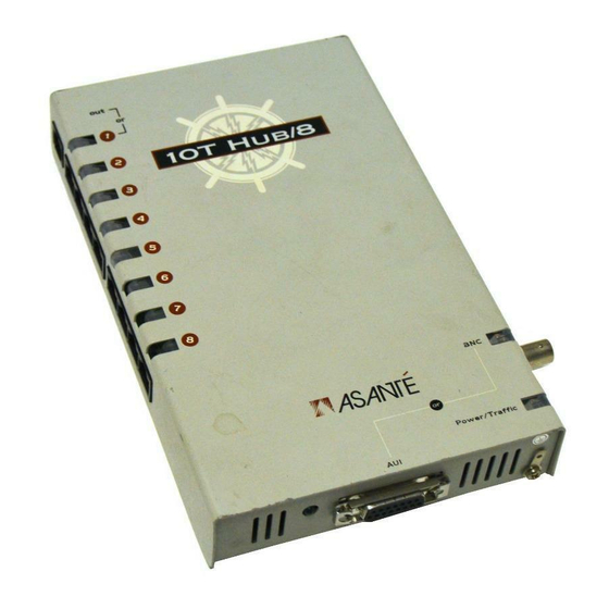
- Page 1 Asanté 10T Hub/8 10T Hub/12 10T Hub/24 for Twisted Pair Networks Installation Guide...
-
Page 2: Trademarks
Disclaimer Information in this document is subject to change without notice and does not represent a commitment on the part of Asanté Technologies, Inc. No part of this manual, or any associated artwork, software, product design or design concept, may be copied, reproduced or stored, in whole or in part, in any form or by any means mechanical, electronic, optical, photocopying, recording or otherwise, including translation to another language or format, without the express written consent of Asanté... -
Page 3: Warranty
Warranty This Asanté 10T Hub/8, 10T Hub/12, or 10T Hub/24 product has a limited lifetime warranty which applies to the original purchaser of the product. Asanté Technologies, Inc. warrants that this product will be free from defects in title, materials and manufacturing workmanship. -
Page 4: Warranty Disclaimers
Warranty Disclaimers Asanté Technologies, Inc. makes no other warranties, express, implied, or otherwise, regarding the 10T Hub/8, 10T Hub/12, or 10T Hub/24, and spe- cifically disclaims any warranty for merchantability or fitness for a particular purpose. The exclusion of implied warranties is not permitted in some states and the exclusions specified herein may not apply to you. -
Page 5: Asking For Assistance
Bulletin Board Service (BBS) (408) 432-1416 ARA BBS (guest log in) (408) 894-0765 AppleLink mail /BBS ASANTE.TECH FTP Archive ftp.asante.com Internet mail support@asante.com 1. Please request catalog of contents. 2. Download INDEX.TXT file for catalog of contents. 3. When sending email, please include your full name, US mailing address, phone number, product name, and a problem description. -
Page 6: Tell Us What You Think
What do you think is the least valuable or weakest part of this manual? What is the most needed improvement you would make to this manual? Fax your comments and suggestions to: Asanté Technical Publications at (408) 894-0363 E-mail them through Internet: techpubs@asante.com Page xi... -
Page 7: Table Of Contents
Table of Contents Disclaimer ..........i Trademarks . - Page 8 10T Hub/8 ........
- Page 9 List of Figures Figure 1-1 Sample network map ......1-4 Figure 2-1 AC Power Adapter ......2-2 Figure 2-2 10BaseT Workstation to Hub Connection .
- Page 10 List of Tables Table 2-1 Power Adapter Specifications ......2-2 Table 3-1 Hub LED Description ......3-3 Table A-1 RJ45 Connector Wiring Description .
-
Page 11: Preface
Preface • About the 10T Hub Family on page xiv • About This Manual on page xvi • About 10BaseT on page xvii • Other Asanté 10BaseT Networking Products on page xviii... -
Page 12: About The 10T Hub Family
Before going any further, examine this package and make sure that what you have is the product you ordered. The package should contain: One 10T Hub/8, 10T Hub/12, or 10T Hub/24, based on what you ordered One Installation Guide (this manual) -
Page 13: Features
A 10BaseT OUT port is provided for cascading hubs in a “tree” configuration The 10T Hub/8 has an autosensed BNC/AUI port; no switch is required The 10T Hub/12 has independent AUI and BNC ports The 10T Hub/12 also provides an optional RJ21 connec-... -
Page 14: About This Manual
About This Manual This manual is divided into four chapters and four appendices: Chapter 1, “Planning a Network Installation” on page 1-1 explains some important considerations when designing and planning your network, and provides the foundation for building reliable, easily managed, and expand- able LANs. -
Page 15: About 10Baset
About 10BaseT About 10BaseT Twisted-pair Ethernet, as defined by the IEEE 802.3 specifications, is called 10BaseT. This is the latest development in the Ethernet evolution and repre- sents a tremendous leap in networking technology. Because 10BaseT uses regular twisted-pair (UTP) telephone wire, it decreases the cost of network- ing. -
Page 16: Other Asanté 10Baset Networking Products
Other Asanté 10BaseT Networking Products To connect your personal computers and other network devices to a 10T Hub, you will need a 10BaseT 10-compatible internal or external adapter for each computer. Asanté Technologies provides a complete line of network interface cards for PCs and the Macintosh, as well as a 10T, BNC, or fiber MAU. -
Page 17: Planning A Network Installation
Planning a Network Installation • Before You Start on page 1-2 • Assign a Network Manager on page 1-3 • Create a Network Map on page 1-4 • Planning for Network Operations on page 1-5... -
Page 18: Before You Start
Planning a Network Installation Before You Start An efficient network that will serve your long-term needs requires thorough planning. This chapter discusses some of the topics that are important in the early stages of network development. The topics are arranged in chronologi- cal order. -
Page 19: Assign A Network Manager
Assign a Network Manager Assign a Network Manager A network manager initially coordinates the design and installation of the network. Once the network is up and running, the network manager is responsible for adding new users to the network and troubleshooting prob- lems. -
Page 20: Create A Network Map
Planning a Network Installation Create a Network Map A network map is a visual record of your network configuration. Create a network map by copying a floor plan diagram and adding graphics repre- senting devices and cabling. Modify the map as you change your plans, and use the completed map as a guide during installation. -
Page 21: Planning For Network Operations
Planning for Network Operations Planning for Network Operations Create a Network Log A network log is a record of the names of devices, locations of wire pairs, wall-jack numbers, and other information about the network. A simple net- work log may contain the name, description, node number, and 10T Hub port number for each device on the network. -
Page 22: Decide Where To Put The 10T Hub
Planning a Network Installation You must use solid copper (not stranded) twisted-pair wiring. You can identify twisted-pair wire by alternating color bands: white/blue, blue/white, white/orange, orange/white, and so on. Use approved building wiring standards or consult a pro- fessional The maximum twisted-pair link-length from hub to transceiver, including the RJ-45 cable, is 100 meters (328 feet). -
Page 23: Installation
Installation • Before You Start on page 2-2 • Plug and Play Installation on page 2-3 • 10BaseT Station to Hub Connection on page 2-4 • Connecting to Thin Coaxial Cable Ethernet on page 2-5 • Connecting to Thick Coaxial Cable Ethernet on page 2-7 •... -
Page 24: Before You Start
Installation Before You Start Before you begin the installation, check the AC voltage of the your country area. The AC power adapter used with your Asanté 10T Hubs or BNC Hubs should have the AC voltage that matches that of your country. Using an AC power adapter with an incorrect AC voltage may damage your hub. -
Page 25: Plug And Play Installation
Plug and Play Installation Plug and Play Installation The Asanté 10T Hubs are designed for plug and play installation. Before you connect the hub to other devices, there are several things you should keep in mind: When connecting two Ethernet devices (such as a hub, Ethernet adapter, or 10BaseT MAU) together, you must make sure that the total modular cable length is not greater than 100 meters. -
Page 26: 10Baset Station To Hub Connection
Installation 10BaseT Station to Hub Connection Do the following steps to connect a 10BaseT Ethernet station to a hub. Make sure the straight-through modular cable distance between the hub and the stations is not greater than 100 meters, including all patch cables and cross-connect wires. Connect one end of the straight through modular cable to any RJ45 port on the hub (except for the OUT port) and another end of the modular cable to the workstation, as shown in Figure 2-2. -
Page 27: Connecting To Thin Coaxial Cable Ethernet
Connecting to Thin Coaxial Cable Ethernet Connecting to Thin Coaxial Cable Ethernet Do the following steps to connect a thin Ethernet configuration. According to the IEEE 802.3 rules, a thin Ethernet segment sup- ports 30 connections over a distance of 185 meters (607 feet). A BNC T-connector is used to connect the thin Ethernet cable. - Page 28 Installation Only one shared port is available on the 10T Hub/8 for either BNC or AUI connection. This port is equipped with two connectors: a BNC connector and an AUI con- nector. The hub autosense circuit can detect which con- nector is in use and no switch needs to be set.
-
Page 29: Connecting To Thick Coaxial Cable Ethernet
Connecting to Thick Coaxial Cable Ethernet Connecting to Thick Coaxial Cable Ethernet The AUI connector on the hubs can be used to connect a 10Base5 thick Ethernet coaxial cable segment to the hub. This allows network stations on the thick coaxial cable to communicate with network stations on the 10BaseT UTP cables. -
Page 30: Connecting Multiple Hubs For A Larger Network
Installation Connecting Multiple Hubs for a Larger Network You have several choices when connecting networks with more than one hub: Use unshielded twisted-pair cable to connect the “OUT” port of port 1 to the “IN” port of another hub in a hierar- chical topology. -
Page 31: Interconnecting Via The Utp Port
Interconnecting via the UTP Port Interconnecting via the UTP Port To interconnect multiple star networks using the UTP ports: Use two, ISO 8877, 8-pin, modular jacks (RJ45) on a length of twisted-pair wire (no longer than 100 meters) that is 24-gauge, solid-conductor, unshielded twisted-pair. -
Page 32: Multiple Hubs Using 10Baset Connection
Installation Multiple Hubs Using 10BaseT Connection Figure 2-6 below illustrates an Ethernet twisted-pair LAN that uses multiple hubs connected together with twisted-pair cables. Up to 8 Hubs Up to 7 Up to 7 Hubs Hubs Up to 7 Up to 7 Stations Stations Figure 2-6 Multiple Hub Configuration... -
Page 33: Interconnecting Via The Bnc Port
Interconnecting via the BNC Port Interconnecting via the BNC Port To connect multiple hubs using the BNC Port on the hubs: Connect each hub to a T-connector on a properly terminated thin cable backbone. Make sure not to exceed the maximum distance length or node count guidelines as specified by the 802.3 specifications. -
Page 34: Wiring Rj21 Installations
Installation Wiring RJ21 Installations The 10T Hub12 provides an additional RJ21 connector to provide an alterna- tive way to wire the workstations to the hub. Instead of having twelve cables going to the RJ45 ports on the hub, a single cable with 25 pins of twisted pair wires inside and RJ21 connectors at the ends can be used instead. -
Page 35: Figure 2-8 Wiring On Rj45 Wall Jack To A Punchdown Block
Wiring RJ21 Installations 1 2 3 4 5 6 7 8 -Row 1: TD+ -Row 2: TD- -Row 3: RD+ -Row 4: TD- RJ45 Figure 2-8 Wiring on RJ45 Wall Jack to a Punchdown Block Connect a network interface card or TP-MAU (if you are using a thick Ethernet card) to the wall jack using twisted pair modular extension cable. -
Page 36: Troubleshooting Your Network
Troubleshooting Your Network • Before You Start on page 3-2 • Interpreting the Hub LEDs on page 3-3 • Testing Your Installation on page 3-4 • Common Problems Found in the Hub on page 3-5 • Diagnosing the Network Interface Card on page 3-7... -
Page 37: Before You Start
Troubleshooting Your Network Before You Start Testing and monitoring your network’s status is done with the aid of the LEDs on the hub, the network interface card, or the 10TMAU. In general, the LEDs give information about the status of a particular unit or function. This section covers how to read the LEDs when testing your installation and dur- ing normal network operation. -
Page 38: Interpreting The Hub Leds
Interpreting the Hub LEDs Interpreting the Hub LEDs When you first turn on your Asanté 10T Hub, all the LEDs switch while the hub goes through a series on internal diagnostics ensuring its reliable operation. After the diagnostics have been completed, each LED indicates a different condition. -
Page 39: Testing Your Installation
Troubleshooting Your Network Testing Your Installation After your installed wiring is connected, you need to begin testing the instal- lation by connecting two network devices that communicate with one another, such as one workstation and one file server. When you have one pair of devices working correctly, you will have verified that the hub func- tions and will know that the link between the workstation and the file server is complete. -
Page 40: Common Problems Found In The Hub
Common Problems Found in the Hub Common Problems Found in the Hub Link Status LED is off. Probable cause is a twisted-pair connector is not making contact. Check all RJ45 connectors. Can also be caused by incorrectly wired twisted-pair cable. Compare wiring to the diagram in the appendix of this manual. -
Page 41: Network Management Software
Troubleshooting Your Network Other workstations connected to hub, disrupting com- muncation of workstations being brought up Remove the disrupting workstations or disable their links. Hub hardware failure is possible, but not likely if it passes the self-test. Network Management Software Network management applications can be categorized into two groups —... -
Page 42: Diagnosing The Network Interface Card
Diagnosing the Network Interface Card Diagnosing the Network Interface Card Most card manufacturers include some form of diagnostic software to ensure the card is functioning properly. Consult the documentation that comes with your network interface card. Page 3-7... -
Page 43: Cable Wiring Diagrams
Cable Wiring Diagrams • RJ45 Connector on page A-2 • AUI (DB15) Connector on page A-3 • Eight-Position (RJ45) Modular Cable on page A-4... -
Page 44: Rj45 Connector
RJ45 Connector Table A-1 RJ45 Connector Wiring Description Symbol Function Signal Type Transmit Data Plus Output Transmit Data Minus Output Receive Data Plus Input No Connection No Connection Receive Data Minus Input No Connection No Connection 1 2 3 4 5 6 7 8 RJ45 12345678 Punchdown Block Pinouts... -
Page 45: Aui (Db15) Connector
AUI (DB15) Connector AUI (DB15) Connector Table A-2 AUI Wiring Description Symbol Pairs Used Transmit Data Out + Pair Data Out - DO S Data Out Shield Receive Data In + Pair Data In - DI S Data In Shield Not Connected Not Connected Not Connected... -
Page 46: Eight-Position (Rj45) Modular Cable
Eight-Position (RJ45) Modular Cable An eight-position modular cable can terminate up to four pairs of a cable; pairs 2 and pairs 3 may be required for 10BaseT. The pin assignments and recommended color code assignments for a 4-pair cable are: Table A-3 RJ45 Color Coding Symbol... -
Page 47: Figure A-4 Rj21 Color Coding
Eight-Position (RJ45) Modular Cable RJ-45 66 Type RJ-21 Connector Connector Block (Amphenol) 1 TD + White/Blue 2 TD - Blue/White Port 1 3 RD + White/Orange 6 RD - Orange/White 1 TD + White/Green 2 TD - Green/White Port 2 3 RD + White/Brown 6 RD -... -
Page 48: Mounting The Hub
Mounting the Hub • Wall Mounting the Hub on page B-2... -
Page 49: Wall Mounting The Hub
Wall Mounting the Hub Your hub can be used as a desktop unit or as a wall mount unit. Two keyhole slots are provided on the bottom of the hub so that it can be mounted on a surface like a wall or the underside of a counter top. Screw two 1/2 inch wood screws 3"... -
Page 50: Technical Specifications
Technical Specifications... -
Page 51: Ieee 802.3 Compliance
IEEE 802.3 Compliance 10BaseT (twisted-pair, UTP) 10Base2 (thin, BNC) 10Base5 (thick, AUI) 10T Hub/8 Eight 10BaseT, UTP ports. Port #1 may work as an IN or an OUT port; all other 10BaseT ports are IN ports. Only RJ45 connectors are provided. -
Page 52: Maximum Cable Lengths
Maximum Cable Lengths 10Base5 (thick Ethernet, AUI): 50 meters maximum to Ethernet MAU (transceiver) with shielded, twisted-pair drop cable. 10Base2 (thin Ethernet, BNC): 185 meters maximum per segment 10BaseT (twisted-pair, UTP): 100 meters maximum, 24 AWG UTP Physical Dimensions All hubs are 8.6 inches x 5.3 inches x 1.35 inches (LxWxH) Environment Temperature: Operating 0 degrees C to +50 degrees C... - Page 53 Index Numerics 10Base5 thick Ethernet 2-7 10BaseT about xiv described xvii using telephone wire 1-2 10BaseT products, other Asanté xviii 10T Hubs about hub family xiv common problems found 3-5 features xv technical specifications C-2 15-pin DIX connector 2-7 50 ohm terminator 2-5 AC power voltage 2-2 adapters, requirements for xviii adding network devices 1-5...
- Page 54 to other devices 2-3 to other hubs. See connecting multiple hubs to thick Ethernet 2-7 to thin Ethernet 2-5 connecting multiple hubs 2-8 restrictions 2-11 using 10BaseT connections 2-10 connecting network segments 2-3 connectors AUI 2-6 BNC 2-5 2-11 DB15. See AUI connector MAU xv RJ21 xv RJ45 2-9...
- Page 55 connecting workstations to hubs 2-9 thin 2-5 expansion, considering future 1-5 features of 10T Hubs xv future expansion, considering 1-5 grounding thin Ethernet 2-5 hierarchical topology 2-8 hierarchy, cascading 2-11 hubs connecting multiple 2-8 LED description 3-3 maximum number 2-10 See also 10T Hubs 2-8 IEEE specifications and Asanté...
- Page 56 Link Status LEDs 3-3 location, determining hub 1-6 manager, network assigning 1-3 responsibilities 1-3 map, network creating 1-4 as installation guide 1-4 sample 1-4 MAU connection xv modular cable distance, straight-through 2-4 specifications A-4 monitoring network status 3-2 multiple hubs, connecting 2-8 2-10 network cable segments 2-3 network installation...
- Page 57 planning network installation 1-1 for network operations 1-5 plug and play installation 2-3 plugging in network segments 2-3 ports AUI xv BNC xv IN 2-3 OUT xv UTP C-2 power adapter specifications 2-2 Power/Traffic LED 3-3 removing network segments 2-3 RJ21 connector xv RJ45 connector 2-9 routine maintenance 3-2...
- Page 58 number of connections 2-5 topology bus xvii hierarchical 2-8 star 1-2 wiring affecting choice of 1-5 TP-MAU (twisted-pair media attachment unit) 2-9 transceiver cable 2-7 troubleshooting 3-2 twisted-pair cable and 10BaseT xvii connecting multiple hubs 2-8 2-10 identifying 1-6 maximum link-length 1-6 twisted-pair Ethernet, about xvii user-serviceable parts 3-2 using installed telephone wire 1-2...
Need help?
Do you have a question about the 10T Hub/8 and is the answer not in the manual?
Questions and answers