
Related Manuals for Shure AUDIOMASTER 1200


Summary of Contents for Shure AUDIOMASTER 1200
- Page 1 Price $7.50 Model 1200 Powermixer SERVICE MANUAL ISSUE NO. 1 Manufactured by SHURE BROTHERS INC. 222 Hartrey Avenue Evanston, Illinois 60202-3696 Printed in U.S.A. Copyright 1988, Shure Brothers Inc. AL954 (HE) 27A8187...
-
Page 2: Specifications
SPECIFICATIONS Output Clipping Level MINIMUM CLIPPING LEVEL Type OUTPUT Mono Powermixer +29 dBV (28 V) SPEAKER Frequency Response +18 dBV (7.9 V) MONITOR Flat +1, -3 dB, 40 Hz to 20 kHz (any input to any output) +18 dBV (7.9 V) PROGRAM MIX Inputs +16 dBV (6.3 V) -
Page 3: Table Of Contents
MODEL 1200 SERVICE MANUAL TABLE OF CONTENTS Description ........1 For Years of Dependable Service . -
Page 5: Description
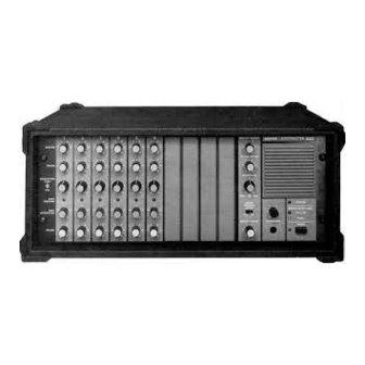
DESCRIPTION ® The Shure Model 1200 AUDIOMASTER Powermixer is a Other effects devices or an equalizer can be connected through compact, flexible microphone mixer with six inputs for high- or a post-master control program loop. An integral power amp low-impedance sources and a 200-watt power amplifier. The limiter prevents overload distortion over a wide signal input range. -
Page 6: For Years Of Dependable Service
(Shure A95UF) to a HI Z input. Phan- DO use a 16 AWG or larger, heavy-duty, 3-conductor extension tom power will not affect balanced low-impedance dynamic cord when additional line cord length is needed. -
Page 7: Service Instructions
PROBABLE CAUSE AND CORRECTION SYMPTOM 1. Adjust INPUT ATTENUATION counterclockwise to reduce INPUT OVERLOAD LED flashing channel input level. NOTE: Occasional flashing is acceptable 2. Reduce input signal level at source. 1. Make sure PHANTOM 24V switch is not on (when not needed). Loud clicks when certain microphones or cables are used 2. -
Page 8: General Service Procedure
PRINTED CIRCUIT BOARD AND PARTS LOCATION FIGURE 1 WARNING CAUTION After replacing high-voltage parts such as the fan, power Similar wire colors and connectors with the same number cord, rear panel convenience receptacle, or printed wir- of pins are used in different circuits; make sure proper ing assemblies SHR-11, SHR-12, or SHR-14 (or their reconnections are made. -
Page 9: Ac Voltage Measurements
To replace the reverb pan, connect the white lead connector AC VOLTAGE MEASUREMENTS to the reverb Input and the orange lead connector to the reverb Numbers within rectangular symbols on the circuit diagrams Output. Use the previously removed screws to secure the reverb denote ac voltages at that point under the following test pan to the reverb shield, and to secure the shield to the chassis conditions:... -
Page 10: Vr1101 Output Voltage Offset
VR1201 TEMPERATURE SENSOR THRESHOLD ADJUSTMENT VR1101 OUTPUT VOLTAGE OFFSET ADJUSTMENT If U1201 or other SHR-12 parts are replaced, VR1201 will 1. Connect a dc voltmeter between SHR-11 terminal AC and probably require recalibration as follows. ground (see Figure 2). 2. Adjust VR1101 so that V1 equals 0 V ±15 mV 1. -
Page 11: Vr1401 Power Amplifier Limiter Threshold
SHR-02 HI-Z INPUT BOARD If any of the heat-sink-mounted parts (voltage regulators To remove SHR-02, remove the six 1/2-inch nuts on the input U1408, U1409 and U1410, or silicon rectifiers D1423 and D1424) jacks. Disconnect the four 3-pin connectors from the SHR-01 is replaced, be sure to apply a small amount of Wakefield Type LO-Z INPUT BOARD and the two 3-pin connectors from the 120 Thermal Joint Compound between the component and the... -
Page 12: S3 Phantom Power Switch
SHR-09 LIMITER BOARD SHR-04 CHANNEL BOARD To free SHR-09 LIMITER BOARD from the Mounting Panel, The SHR-04 Channel Boards are assembled and installed in remove from the front of the panel the two Phillips screws that pairs. Therefore, SHR-04s for Channel 1 and Channel 2 constitute attach the Limiter Switch to the panel. -
Page 13: A1200Mx Input Expansion Module
The following optional accessories are designed for use with if any of the following conditions are not met, the transistor the Shure 1200 AUDIOMASTER Powermixer. should be replaced. See Figure 3 for active component lead Carrying Case ....... A1200C codes. -
Page 14: Replacement Parts List
REPLACEMENT PARTS LIST The following list provides information on replacement parts for the Shure Model 1200 AUDIOMASTER Powermixer. Shure part numbers are given for all parts and, where available, manufacturer’s name and part number for acceptable equivalents in parentheses following the part description (note that for optimum performance, only direct replacement parts should be used). - Page 15 SHURE REFERENCE DESIGNATON PART NO. DESCRIPTION 802583FK Knob, Red 802584FK Knob, Blue 802585FK Knob, White 802587FK Fan Grille, Front Panel MP10 802642FK Fan Grille, Rear Panel P1003-P1004 802628FK Connector, Receptacle, 2-pin 711080FK Connector, Receptacle, 8-pin P1401 Q501, Q1110, Q1403 706102FK...
- Page 16 SHURE REFERENCE DESIGNATION PART NO. DESCRIPTION R1126-R1127 802612FK Resistor, Ceramic, Dual, .22, 5 W R1128 708853FK Resistor, 22 K 710041FK Resistor, Ceramic, 10, 5 W R1301 801064FK Resistor, 18 K R1402 801080FK Resistor, 390 K R1403, R1454 Resistor, 22, 1/2 W...
- Page 25 CIRCUIT DIAGRAM-1 (SHR-01, SHR-02, SHR-03, SHR-04)
- Page 26 CIRCUIT DIAGRAM-2 (SHR-05, SHR-07, SHR-08, SHR-10)
- Page 27 CIRCUIT DIAGRAM-3 (SHR-09, SHR-12, SHR-14)
- Page 28 CIRCUIT DIAGRAM-4 (SHR-06, SHR-11, SHR-13, SHR-14)
Need help?
Do you have a question about the AUDIOMASTER 1200 and is the answer not in the manual?
Questions and answers