
Related Manuals for Anthem AVM 40


Summary of Contents for Anthem AVM 40
- Page 1 AVM 40 OPERATING MANUAL UPDATES: www.anthemAV.com S O F T W A R E V E R S I O N 1 . 0 x ™...
-
Page 2: Safety Precautions
SAFETY PRECAUTIONS READ THIS SECTION CAREFULLY BEFORE PROCEEDING! WARNING RISK OF ELECTRIC SHOCK DO NOT OPEN WARNING: TO REDUCE THE RISK OF ELECTRIC SHOCK, DO NOT REMOVE COVER (OR BACK). NO USER-SERVICEABLE PARTS INSIDE. REFER SERVICING TO QUALIFIED SERVICE PERSONNEL. The lightning flash with arrowpoint within an equilateral triangle warns of the presence of uninsulated “dangerous voltage”... - Page 3 8. Ventilation – Slots and openings in the cabinet are provided for ventilation and to ensure reliable operation of the product and to protect it from overheating, and these openings must not be blocked or covered. The openings should never be blocked by placing the product on a bed, sofa, rug, or other similar surface. This product should not be placed in a built-in installation such as a bookcase or rack unless proper ventilation is provided or the manufacturer’s instructions have been adhered to.
- Page 4 Anthem, AnthemLogic and the Anthem logo are trademarks or registered trademarks of Sonic Frontiers International. Paradigm is a registered trademark of Paradigm Electronics Inc. All other trademarks are the property of their respective owners.
-
Page 5: Table Of Contents
1.1 Before Operating Your AVM 40 ........ - Page 6 4. OPERATION 4.1 Power On and Off ..............43 4.2 Path Selection .
- Page 7 Appendix A – IR Macros for Surround Modes and FM • AM Banks Appendix B – Preset Memory Codes Specifications Warranty Big Pictures of Front and Rear Panels Inside Back Cover...
-
Page 9: Introduction
Thank you for purchasing the Anthem AVM 40. The AVM 40 is a home theater audio processor with HDMI switching and video transcoding, multizone capabilities, and FM/AM tuner. Anthem products are engineered to recreate the passion of a live musical performance and thrill of the very best movie theaters by using the highest level of circuit design, proprietary software, superior build quality, innovative features, and intuitive ergonomics with tremendous flexibility. -
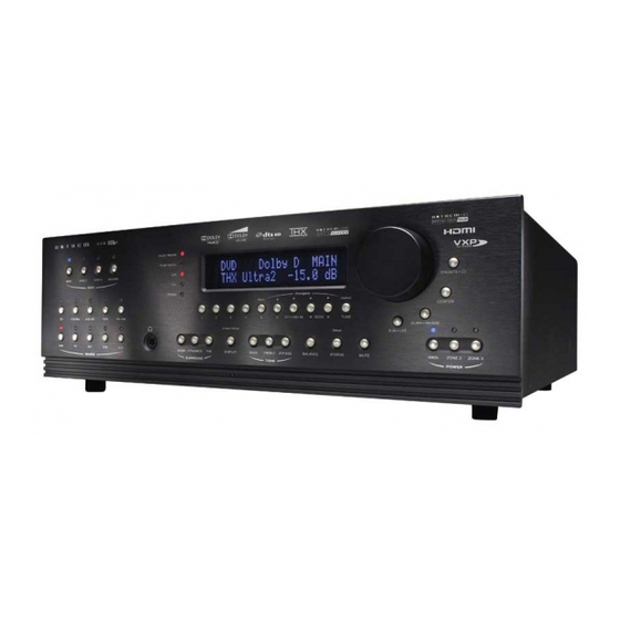
Page 10: Front Panel
1. INTRODUCTION continued … FRONT PANEL 1 – Path selection 7 – Surround Mode / Headphone settings for Level / Bass / Treble / Balance 2 – Mode / Surround Decoder indicators 8 – Subwoofer / LFE Level settings 3 – Display 9 –... -
Page 11: Front Panel Display
1. INTRODUCTION continued … FRONT PANEL DISPLAY MAIN Display Example: DVD1 Dolby D MAIN 5.1+PLIIx Movie 480i 1 – Source selection. 2 – Audio Input Format or Sleep indication if engaged. 3 – Path that the information on the display refers to. 4 –... -
Page 12: Rear Panel
1. INTRODUCTION continued … REAR PANEL SHOCK HAZARD E X P A N S I O N P O R T DO N O T OPE N . RISQUE DE CHOC ÉLECTRIQUE NE P AS OUVRIR SUB 2 M A I N A U D I O - O U T M A I N A U D I O - O U T... -
Page 13: Remote Control
3 – Power ON for MAIN, ZONE2, and ZONE3 control modes Power ON/OFF for other control modes (see #4) This key does not turn the AVM 40 off (see #31) 4 – Control mode (to control other components) SSP PATH... -
Page 14: Speaker Placement
1. INTRODUCTION continued … SPEAKER PLACEMENT These illustrations show the typical speaker placement for a 7.1-channel surround system (the ‘.1’ speaker is the subwoofer). Ideally, the Surround and Rear speakers should be positioned 2-3 feet above ear level. The subwoofer can be placed in any location where severe resonances are prevented – see section 3.2. 5 and 6 are not used in a 5.1 system Front-Left Front-Right... -
Page 15: Interconnects
These illustrations show various audio, video, and 12V trigger connectors that are used between source components, the AVM 40, monitors, and power amplifiers. Note that when RCA cables have coaxial construction and their impedance is 75 ohms, they are equally suitable for analog video and digital audio. -
Page 16: Connections
MAIN or ZONE2 (see section 3.8). HDMI (digital): Audio and video are transmitted from source components to the AVM 40. Maximum video resolution is 1080p/60. Audio is transmitted as Dolby Digital, DTS, or up to six channels of PCM. Connect HDMI output to a monitor with HDMI or DVI input –... -
Page 17: Audio Connections
Use the HDMI inputs if your monitor has HDCP-compliant HDMI or DVI input, otherwise use the coaxial or optical inputs. The AVM 40 also provides one balanced AES/EBU connection, which is used on professional equipment. Any digital input can be assigned to any number of Sources that are set to ‘Digital’. To change digital audio connection from the factory default assignments, see section 3.5. - Page 18 Balanced connection offers the highest transmission quality over long cable lengths, because it rejects noise and hum pickup. In the AVM 40, XLR output voltage is twice that of RCA (6 dB higher). The RCA outputs and the XLR outputs are active at the same time.
-
Page 19: Fm • Am Antennas
Depending on the equipment, a thicker wire gauge may be required (consult your dealer). The AVM 40 provides flexible trigger options. From the factory, all the triggers are disabled. Through the Setup Menu, you can specify the conditions for enabling triggers (see section 3.10). - Page 20 2. CONNECTIONS continued … Example 1: DVD Player to AVM 40 to Main TV HDTV receivers are connected the same way as DVD players. HDMI IN SHOCK HAZARD E X P A N S I O N P O R T DO N O T OPE N .
- Page 21 2. CONNECTIONS continued … Example 2: Video Recorder to AVM 40 EJECT SHOCK HAZARD E X P A N S I O N P O R T DO N O T OPE N . RISQUE DE CHOC ÉLECTRIQUE NE P AS OUVRIR...
- Page 22 2. CONNECTIONS continued … Example 3: AVM 40 to Amplifiers and Subwoofer (Balanced connection shown, single-ended is similar) To powered SHOCK HAZARD E X PA N S I O N P O R T DO NOT OPEN. subwoofer RISQUE DE CHOC ÉLECTRIQUE...
-
Page 23: Setup Menu
3. SETUP MENU For optimum performance and enjoyment, it is crucial that your AVM 40 be properly set up. This may appear like a lot of work, however, most settings do not need to be changed from the factory defaults. -
Page 24: Set Time And Timers
SET TIME / TIMERS The time and day, plus 6 different timers are set in this menu. The timers in the AVM 40 are like an alarm clock, but allow two different timer settings for each of MAIN, ZONE2, and ZONE3. - Page 25 T1 or T2 WEEKEND OFF: Sets the Saturday and Sunday turn-off time. Timers may also be set to only turn on or only turn off (see Example 2) – this way, the AVM 40 can be set to turn on automatically, and it won’t turn off until you turn it off manually when you’re done for the day.
- Page 26 3. SETUP MENU continued … Example 1: Select a Source for the ZONE2 Timer: • Enter the Setup Menu. Go to ‘1. SET TIME/TIMERS’ and press SELECT. • Press the button until you reach ‘f. SET ZONE2 TIMERS’. • Press SELECT. The ‘1f. SET ZONE2 TIMERS’ submenu will appear. •...
-
Page 27: Speaker Configuration
Here you will also set up the bass management. Entering information about the size of your speakers will enable the AVM 40 to control bass information so it is not lost or distorted by smaller speakers that are unable to reproduce large amounts of bass. - Page 28 3. SETUP MENU continued … Highlighting ‘a. CINEMA SPKR CONFIGURATION’ in menu 2 and then pressing SELECT displays this menu: 2a. CINEMA SPKR CONFIGURATION L/R FRONTS : Small CENTER : Small L/R SURROUNDS : Small 7.1-L/R REARS : Small SUBWOOFER : 1 Sub XOVER FREQ : 80 THX ADV SETTINGS : Off L/R FRONTS XOVER :...
- Page 29 If your subwoofer has phase and/or polarity controls, set them to zero/normal before making any adjustments to the AVM 40’s Subwoofer Phase and Polarity settings. As a general guide, set Polarity to ‘Normal’ if the subwoofer is placed close to the front speakers, and to ‘Inverted’...
- Page 30 Rooms often have a single prominent resonance peak which can make bass sound boomy, even with the finest subwoofer. The AVM 40 has a proprietary set of low frequency test tones that allow you to find and easily remove that resonance peak.
- Page 31 • Use the buttons to change to ‘Yes’. • Press SELECT and ‘a. CURRENT LEVEL’ will change to the new setting. The AVM 40 will not allow bass output to exceed this new setting. • Press BACK to leave the submenu.
-
Page 32: Listener Position
AVM 40 can delay the sound coming from speakers that are closer to the listener. -
Page 33: Speaker Level Calibration
TEST SEQUENCE to ‘Auto’ using the buttons and then pressing SELECT. If the previously selected Source is Anlg-Dir, the AVM 40 switches to FM • AM, which is always Anlg-DSP, for the duration of the test noise. (‘Anlg-Dir’ bypasses the test noise generator.) Use of a Sound Pressure Level meter is strongly recommended, especially for setting the subwoofer level. - Page 34 3. SETUP MENU continued … Procedure for Manual Test Sequence: • Enter the Setup Menu. Go to ‘4. SPEAKER LVL CALIBRATION’ and press SELECT. • Use the buttons to set TEST SEQUENCE to ‘Manual’. • Press the buttons to go from speaker to speaker. •...
-
Page 35: Source Setup And Presets
3. SETUP MENU continued … SOURCE SETUP / PRESETS This is where you set up each Source and Path according to how you want them to be used. SOURCE SETUP / PRESETS 2-Ch 6-Ch TAPE FM/AM DVD1 DVD2 DVD3 DVD4 SAT1 SAT2 r. - Page 36 3. SETUP MENU continued … Highlighting ‘f. DVD1’ in menu 5 then pressing SELECT displays this menu – the other submenus are similar: DVD1 SETUP / PRESETS RENAME : DVD1 CONVERTER IN : HDMI1 HDMI REPEATER : Yes IF YCbCr IN : Auto IF RGB IN : Studio f.
- Page 37 Auto Digital (applies to MAIN only): When set to ‘Yes’, the AVM 40 switches to Digital when it senses a digital bitstream and to Analog-DSP when it doesn’t. This feature is useful with digital cable boxes that use the digital output for digital channels and analog output for analog channels.
- Page 38 Mode Presets (MAIN only): When you or another member of your family uses the AVM 40, the Mode and THX presets that are set here are recalled, ensuring trouble-free operation. The presets are applied whenever a Source is selected or MAIN power is turned on.
- Page 39 3. SETUP MENU continued … Example 1: Rename AUX to ‘GAME’. • Enter the Setup Menu. Go to ‘5. SOURCE SETUP / PRESETS’ and press SELECT. • Press the button until you reach ‘q. AUX’ and press SELECT. • ‘a. RENAME: AUX’ will be highlighted in red. •...
-
Page 40: Adjust Input Levels
Then, as you switch through each highlighted Source, you will hear that component play. This lets you know that each component is connected to the AVM 40, and it also allows for easy comparative level adjustments of analog sources. Remember, adjusting input levels only functions with Sources set to Analog in menu 5, and the bar graph only works with Analog-DSP setting. -
Page 41: Adc And Audio Output
6-Ch input is selected, set REVERSE SUR/REAR to ‘Yes’ and re-connect the AVM 40 as follows: Surround outputs on the AVM 40 to the Rear inputs on your amplifier, and the Rear AVM 40 outputs to the Surround amplifier inputs. The 6-Ch Surround inputs will now play through your Rear speakers. The AVM 40 flips the SUR/REAR channels back to normal whenever a mode with 6.1 or 7.1 output is turned on for the 6-Ch input... -
Page 42: Video Output
3. SETUP MENU continued … VIDEO OUTPUT In this menu, enter the characteristics of your display’s video input. Items a. through g. pertain to MAIN output. Using item h. you can also configure the second Component video output for ZONE2 video switching. Changes do not take place immediately to prevent loss of On-Screen display as you scroll through settings. -
Page 43: Volumes And Rename Paths
This avoids any potential ‘surprises’ of not knowing the volume someone had set when turning the AVM 40 off, and then having the power-on volume be either too loud or quiet. -
Page 44: Triggers, Ir, And Rs-232
TRIGGERS / IR / RS-232 When a trigger output on the AVM 40 is connected to the trigger input of another component, such as a power amplifier or video projector, the AVM 40 can turn the component on or off according to the trigger’s Setup. - Page 45 This allows you to enable or disable the AVM 40’s infra-red inputs. Being able to do so can be useful when an IR receiver, connected to the AVM 40, is located in the same room as the AVM 40. In such a case, the AVM 40 can receive two IR signals for the same command –...
-
Page 46: Displays And Timeout
From here, select the Path adjustments that are shown by the MAIN or ZONE2 On-Screen displays. For example, if ZONE2 is set up with an IR repeater for the Remote Control, and you are using the AVM 40 in the MAIN room, you may not want to be disturbed by information about adjustments made in ZONE2 by someone else. - Page 47 3. SETUP MENU continued … Example: Set the position of the MAIN On-Screen information to the middle of the monitor. • Enter the Setup Menu. Go to ‘11. DISPLAYS/TIMEOUT’ and press SELECT. • Press the button until you reach ‘c. MAIN OS POS’N: Bottom’. •...
-
Page 48: Save And Restore Settings
Restore or Reload Settings: You may RESTORE USER SETTINGS, INSTALLER SETTINGS, or RELOAD FACTORY DEFAULTS at will. The AVM 40 will prompt you to confirm that you want to replace the current settings – press BACK at this point to abort a restore. - Page 49 3. SETUP MENU continued … Example 1: Save User Settings. FM • AM Tuner presets will also be saved in USER SETTINGS. • Enter the Setup Menu. Go to ‘12. SAVE/RESTORE SETTINGS’ and press SELECT. • Upon entering this menu item, ‘a. SAVE USER SETTINGS’ will be highlighted in red. •...
-
Page 50: Lockout And Passwords
3. SETUP MENU continued … 3.13 LOCKOUT / PASSWORDS Passwords are used to protect the saved User and Installer settings. Once you have set a password, it can also be used as a Lockout to prevent settings from being changed by anyone without one of the passwords. 13. -
Page 51: Power On And Off
4. OPERATION POWER ON/OFF When turned on, the AVM 40 comes on at the pre-programmed volume setting (see section 3.9). Always turn the power amplifier on last to prevent ‘turn-on pops’ when other components are turned on. Front Panel – Power ON Main Choose one of the following: •... -
Page 52: Manually Copying The Main Path To Zone2/3 And Record
ZONE3, TAPE, and VCR outputs. This can be done by the DVD player or the AVM 40: • AVM 40 Down-mix: If the digital audio output from your DVD player is connected to the AVM 40, the AVM 40 down-mixes 5.1 channels into 2.0 whenever you copy MAIN to another Path. This applies whether the input is, Dolby Digital, DTS, or 6-Ch input. -
Page 53: Fm • Am Tuner
… 4.4.1 FM • AM TUNER The AVM 40 has a built-in FM • AM tuner, which is common to all Paths. The station that is selected in either MAIN, ZONE2, ZONE3, or RECORD is shared with all other Paths. -
Page 54: Volume Control
SURROUND MODE LEVELS The AVM 40 memorizes the level of one group of channels relative to another separately for each surround mode (section 4.8), and for the 6-Ch input. To make a change for the surround mode that is currently playing,... -
Page 55: Bass, Treble, And Balance
Dolby Pro Logic must be turned on manually by selecting it in the Mode options. 5.1- and 6.1-Channel Source Material: The AVM 40 detects the digital format that you select on each DVD and automatically engages decoding for the selected format. -
Page 56: Anthemlogic
Dolby Digital 2.0 soundtracks with surround encoding contain a flag that can be used to automatically activate Pro Logic IIx Movie mode. The AVM 40 can be set to either use this flag or to override it. To find out if the Dolby Digital 2.0 material being played has the surround flag, press MODE. If flagged, the first line of the display says “DOLBY D 2.0 SUR AUTO”... -
Page 57: Surround Modes For 2.0-Channel Source Material
The Center channel is not used. AnthemLogic-Cinema: 7.1 – Another proprietary mode from Anthem, designed to provide the impact of a large theater experience from 2-channel movies and TV programs. Pro Logic IIx Music: 7.1 –... -
Page 58: Dts-Es
There are two ways that Rear channel information is encoded in DTS-ES – Matrix and Discrete: • Matrix – DTS-ES Matrix movies contain a matrixed Rear channel. The AVM 40 automatically engages Neo:6 to decode DTS-ES Matrix. Neo:6 can also be turned on manually and applied to any other 5.1-channel material –... - Page 59 4. OPERATION continued … • Adaptive Decorrelation – In a movie theatre, a large number of surround speakers help create an enveloping surround sound experience, but in a home theatre there are usually only two speakers. Unless you are using properly positioned dipoles, surround speakers can sound like headphones that lack spaciousness and envelopment –...
- Page 60 Surround EX technology are able to reproduce an extra channel which has been added during the mixing of the program. This channel (called Surround Back, but named Rear in the AVM 40), places sounds behind the listener in addition to the currently available L-Front, Center, R-Front, R-Surround, L-Surround and Subwoofer channels.
- Page 61 4. OPERATION continued … THX Ultra2 Overview Key: Re-EQ – De-emphasizes treble. May be turned on or off at any time after pressing THX twice. Timbre – Matches the sound character, or timbre, of the surround channels to the front channels. Adp-Decor –...
-
Page 62: Mode And Thx Operation For 2.0-Channel Source Material
4. OPERATION continued … 4.8.7 Mode and THX Operation for 2.0-Channel Source Material – To make all Modes available, turn THX Off. Cycle through Modes and THX using Master Control Knob or keys on remote control. Stereo (2-Ch) Press MODE preset info in AnthemLogic-Music (6.1) section 3.5... -
Page 63: Mode And Thx Operation For Dolby Digital 5.1 And 6-Ch S/E
4. OPERATION continued … 4.8.8 Mode and THX Operation for Dolby Digital 5.1 and 6-Ch S/E – To make all Modes available, turn THX Off. Cycle through Modes and THX using Master Control Knob or keys on remote control. THX Options Press THX None (5.1) THX Cinema... -
Page 64: Mode And Thx Operation For Dts Source Material
4. OPERATION continued … 4.8.9 Mode and THX Operation for DTS Source Material – To make all Modes available, turn THX Off. Cycle through Modes and THX using Master Control Knob or keys on remote control. THX Options None (5.1) Press THX THX Cinema Press MODE... -
Page 65: Dynamics
If you would like to go sleep while listening to a program or music, the Sleep Timer will automatically turn the AVM 40 power off after a preselected time. So when you find yourself falling asleep at the TV, take the Remote Control and: •... -
Page 66: Enable And Disable Timers
• All Timers: Enabled or Disabled (sections 3.1 and 4.13). • Serial Number: If the number on the rear panel does not match this, contact Anthem immediately. When in ZONE2 or ZONE3, information relating only to the selected Path is displayed. -
Page 67: Entering Preset Memory Codes
Appendix B at the back of this manual contains setup codes for controlling other components in your system with the AVM 40 Remote Control. If a component is not listed, see section 5.2. To enter a code: 1. Press the control mode key at the top (e.g. DVD). -
Page 68: Learning A Command
… LEARNING A COMMAND The AVM 40 Remote Control has the ability to learn the command of an individual key from almost any other remote control. When a new command is programmed onto a key, the pre-programmed command is still available by pressing LEARN before pressing the key (Layer1). -
Page 69: Programming Macros
… PROGRAMMING MACROS Macros are used to execute multiple functions with a single key press, such as powering the AVM 40, cable box, and monitor On at the same time. Up to 32 commands total can be programmed. Programming a Macro that works regardless of control mode setting: 1. -
Page 70: Software Version Identification
SOFTWARE VERSION IDENTIFICATION To find out which software version is in your AVM 40, press STATUS and the display will show it. The latest software is available from our web site. A list of changes comes with the download. If operating manual updates aren’t also included, or if you haven’t been keeping up with the upgrades, it’s a major upgrade, so... - Page 71 8. Using the serial cable, connect your computer to the AVM 40 via the RS-232 port on the rear panel. Updating does not require moving the AVM 40 or disconnecting it from your system, as long as you can connect your computer to the RS-232 port.
- Page 72 • You can program your source selection keys with the power-on command preceding each source-select command. This way, when a Source is selected, the AVM 40 will turn on at the same time if it is off, similar to Front Panel operation.
-
Page 73: Appendix B – Preset Memory Codes
2. Press and hold LEARN until the LED flashes twice. 3. Enter the 5-digit code. Two LED blinks indicate that the code is accepted. Audiovox 31390, 31627 Onkyo 30135, 31298, 30842, 30380, Anthem Preamplifiers: AVLight 30158 31531 Bel Canto Design 31584... - Page 74 APPENDIX B – PRESET MEMORY CODES continued … Regal 00279, 00273, 00259, 00020 30072, 31294, 30655 Cable Converters: Regency 00002 Kenwood 30681, 30826, 30626, 30028, 00003, 00008, 00014, 00001, Rembrandt 00011 30037, 30036, 30190 00007, 00013, 00011, 00017 Runco 00000 31318 Allegro 00315, 00153...
- Page 75 APPENDIX B – PRESET MEMORY CODES continued … Microsoft 20522 DVD Players: Satellite Receivers: Mintek 20839, 20717 Adcom 21094 AlphaStar 00772 Mitsubishi 21521, 20521 Advent 21016 Chaparral 00216 Momitsu 21082 Aiwa 20641, 21912 Crossdigital 01109 20785 Akai 20899, 20770, 21975, 21089 DirecTV 00392, 00566, 00639, 01639, Nesa...
- Page 76 APPENDIX B – PRESET MEMORY CODES continued … Curtis Mathes 10047, 10054, 10154, 10451, Huafa 10145 TVs: 10093, 10060, 10702, 10030, Huanghe 10817 10264 10145, 10166, 10466, 11347, Huangshan 10264, 10817 A-Mark 10003 10039, 10056, 11147, 10016, Huanyu 11910, 10817, 10264 Abex 10032 11919...
- Page 77 APPENDIX B – PRESET MEMORY CODES continued … 11447, 10047, 11454, 10000, 10381, 11944, 10020, 10096 TVs continued: 10030, 10178, 10679, 11247, Symphonic 10180, 10171, 11913, 11904 Minutz 10021 11917, 10090, 11948, 11147, Synco 10000, 10451, 10093, 10060, Mitsubishi 10154, 10250, 10093, 10236, 10019, 11907, 11922, 10135, 10178, 10092, 10036, 10474 10180, 11250, 10150, 10030,...
- Page 78 APPENDIX B – PRESET MEMORY CODES continued … 20166, 20105, 20089 21060, 20761 VCRs: Howard Computers 21972 Protec 20072 21972 21972 Pulsar 20039 Admiral 20048, 20209 21944 Qisheng 20060 Adventura 20000 Hughes Network Sys 20042, 21949, 20739 Quarter 20046 Aiko 20278 Hyundai 21951...
- Page 79 APPENDIX B – PRESET MEMORY CODES continued … MyHD 01383 VCRs continued: Video Accessories: Northgate 01272 Villain 20000 01272 Panasonic 01120 Wards 20060, 20035, 20048, 20047, Alienware 01272 Pinnacle Systems 01268 20081, 20240, 20000, 20042, CyberPower 01272 Pioneer 01010 20072, 20062, 20212, 20760 Gateway 01272 Princeton...
-
Page 80: Specifications
SPECIFICATIONS ANALOG VIDEO SWITCHING Bandwidth from input jack to output jack (bypass mode for component video) Composite & S-Video ............70 MHz Component: Y . - Page 81 SPECIFICATIONS continued … MAIN Path (RCA & XLR output) Frequency Response and Bandwidth Analog-Direct Inputs ....10 Hz to 20 kHz (+0, -0.2 dB), 1 Hz to 120 kHz (+0, -3 dB) Analog-DSP Inputs at 24/96 .
- Page 82 Pinout (AVM 40 side) ........
-
Page 83: Warranty
Warranty is void if the Anthem product is not purchased from an Authorized Anthem Dealer, if the serial number has been removed, altered, or defaced, if the product has been operated or handled other than in accordance with the instructions in its Operating Manual or otherwise abused, misused, damaged by accident or while in transport, tampered with, modified, or repaired by anyone other than Anthem Electronics or an authorized Anthem Electronics service center. - Page 86 D E S I G N E D A N D M A N U F A C T U R E D I N N O R T H A M E R I C A t e l . ( + 1 ) 9 0 5 - 3 6 2 - 0 9 5 8 M - F 9 : 0 0 a m - 5 : 3 0 p m ( E S T ) w w w .
Need help?
Do you have a question about the AVM 40 and is the answer not in the manual?
Questions and answers