
Related Manuals for Anthem AVM 20


Summary of Contents for Anthem AVM 20
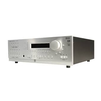
- Page 1 AVM 20 OPERATING MANUAL UPDATES: www.anthemAV.com S O F T W A R E V E R S I O N 2 . 0 x...
- Page 2 Copyright Anthem /Sonic Frontiers International. All rights reserved. The information contained herein may not be reproduced © ™ in whole or in part without our express written permission. ANTHEM ™ is a trademark of Sonic Frontiers International. All other trademarks are the property of their respective owners.
-
Page 3: Table Of Contents
1.2 Receiving and Unpacking the AVM 20 ........ - Page 4 6.1 Powering the AVM 20 ON and OFF ....... . .
- Page 5 Deleting a Learned Command from a Key 6.8 Teaching the AVM 20 Remote Control to Universal Learning Remotes ..... . 40 7.
-
Page 6: Introduction
Section 1 contains important handling and safety information. Section 2 contains a Quick Start Guide which shows you how to connect most popular components to the AVM 20 and get up and running in a matter of minutes. Section 3 describes the Front Panel, Rear Panel, and Remote Control layouts of the AVM 20, while Section 4 describes connections in detail. -
Page 7: Important Safety Information
1.3.1 BEFORE OPERATING YOUR AVM 20 • Do not connect power to the AVM 20 if there are signs of damage to any part of its exterior surface. • Situate the AVM 20 away from heat sources such as radiators, heat registers, stoves, or other any appliances (including power amplifiers) that produce heat. -
Page 8: Supply Power Requirements
60 Hz. The power transformer primary cannot be changed from 120V to 240V operation. The AVM 20 uses a polarized power cord with one blade wider than the other so that it only fits into the outlet one way. If the plug cannot be fully inserted with no blade exposed, reverse the plug and try again. If it still does not fit, you have an obsolete outlet –... -
Page 9: Quick Start
From the AVM 20, connect Analog Audio-Out/Sub1 to the subwoofer’s line/low level input. Reconnect the power to all components and turn them on. To turn on the AVM 20, move the switch on the rear panel to the ‘on’ position and then press the POWER – MAIN button on the front panel. -
Page 10: Connector Diagrams And Descriptions
For more information see sections 4.2.1 and 7.4.2. Note about Your Speakers: • The AVM 20 allows you to enter information about how many speakers you have in your system, as well as their relative size, type, and distance from your listening position. This speaker setup information is important in directing audio signals optimally, ensuring you get the best quality sound from your system. -
Page 11: Cd Player To Avm 20
2. QUICK START continued … 2.2.1 CD Player to AVM 20 CD Player Track 1 CD Player Audio Out EJECT Amplifier(s) -
Page 12: Dvd Player And Tv To Avm 20
2. QUICK START continued … 2.2.2 DVD Player and TV to AVM 20 Rear Panel of TV Audio Relay Composite CATV Trigger Video In Component Video In Vari Fixed S-Video In Note: Component Video use is optional Amplifier(s) (see sections 4.3.3 and 7.4.10) -
Page 13: Vcr And Tv To Avm 20
2. QUICK START continued … 2.2.3 VCR and TV to AVM 20 Rear Panel of TV Audio Relay Composite CATV Trigger Video In Component Video In Vari Fixed S-Video In EJECT Amplifier(s) Video Audio Composite Relay Trigger In S-Video... -
Page 14: Avm 20 To Amplifier And Powered Subwoofer (Rca)
2. QUICK START continued … 2.2.4 AVM 20 to Amplifier and Powered Subwoofer (RCA) Powered Subwoofer Input Level P V A T R I G G E R S REAR REAR MADE IN CANADA INPUT THIS PRODUCT IS BUILT WITH THE FOLLOWING PATENTS: CDN. -
Page 15: Avm 20 To Amplifiers And Powered Subwoofer (Xlr)
2. QUICK START continued … 2.2.5 AVM 20 to Amplifiers and Powered Subwoofer (XLR) To powered subwoofer Trigger Setup Suggestion: With triggered amplifiers it is possible to automatically turn power on to the 2-channel amplifier only when, for example, Tape or FM•AM is selected, and both amplifiers when DVD or SAT is selected (see section 7.4.9). -
Page 16: Speaker Placement
Subwoofer For optimal results, the size of the speakers and the distance of each speaker to the listening position should be entered in the Setup of the AVM 20 (see sections 7.4.4, 7.4.5, and 7.4.6). beside listening position 90˚ from center slightly behind listening position 110˚... -
Page 17: Panels / Displays / Remote Layout
3. PANELS / DISPLAY/ REMOTE LAYOUT FRONT PANEL LAYOUT The front panel of the AVM 20 has the Master Control Knob, selection/navigation buttons, a display, status indicator LEDs, and the Headphone jack . LOGIC LOGIC 1 – Path selection 7 – Individual Speaker / Headphone settings for Level / Bass / Treble / Balance 2 –... -
Page 18: Front Panel Display
3. PANELS / DISPLAY/ REMOTE LAYOUT continued … FRONT PANEL DISPLAY MAIN Display Example: 1 – Source selection (see section 5.4). 2 – Audio Input Format (see section 7.4.2) or Sleep Indicator if engaged (see section 6.5). 3 – Path that the information on the display refers to (see section 5.2). 4 –... -
Page 19: Rear Panel Layout
REAR PANEL LAYOUT The rear panel of the AVM 20 contains all connections, such as AC power connection, audio and video inputs and outputs, FM and AM antenna connections, and the RS-232 port which allows software upgrades and external control of the AVM 20. -
Page 20: Remote Control Layout
REMOTE CONTROL LAYOUT 1 – IR Transmitter (front face) 2 – Transmission Indicator LED (red) 3 – AVM 20 Power ON when in MAIN, ZONE2, or ZONE3 personality Power ON/OFF for other components (see #4) PATH Note: This does not turn the AVM 20 off (see #31) MAIN 4 –... -
Page 21: Connections
4. CONNECTIONS CONNECTING POWER TO THE AVM 20 Connect the power cord to the back of the AVM 20 and then to a 105 to 130 Volt, 60 Hz AC outlet. AUDIO CONNECTIONS There are two methods of transmitting audio signals: Analog and Digital. Analog is an electrical waveform representation of sound and requires one cable for each channel. -
Page 22: Left / Right Analog Audio Inputs
– connect DVD-A player video output to the DVD input (sections 4.3 and 7.4.2). The 2-Ch BAL and 6-Ch S/E inputs can be set to either bypass all digital stages in the AVM 20 or to include digital stages, so that bass management, time alignment, bass/treble control, surround modes, and THX post- processing can be enabled (see sections 5.7, 5.8, 7.4.2, and 7.4.5). -
Page 23: Video Connections
Note that video format conversion is not performed – if S-Video is used from your VCR, only the S-Video output of the AVM 20 will have a signal to send to your TV monitor whenever the VCR Source is selected. - Page 24 4. CONNECTIONS continued … DVD Player, Satellite Receiver, and TV Connections with AVM 20 as Video Input Selector Rear Panel of TV Audio Relay Composite CATV Trigger Video In Component Video In Vari Fixed S-Video In SATELLITE Note: Component Video use is optional (see sections 4.3.3...
-
Page 25: Before Operating Your Avm
Note: For installers – The AVM 20’s IR inputs sense pulses from an IR repeater, not data. If using a control system that sends IR data, an emitter must be used face-to-face with an IR repeater. -
Page 26: Front Panel Operation
(ZONE2 and ZONE3 Paths). POWER ON/OFF When turned on, the AVM 20 will have all of the same settings it had when it was last turned off, except for Volume, which comes on at the pre-programmed value (see section 7.4.7). -
Page 27: Copying The Main Path To Zone2, Zone3, Or Record
ZONE3, TAPE, and VCR outputs. This can be done by the DVD player or the AVM 20: • AVM 20 Down-mix: If the digital audio output from your DVD player is connected to the AVM 20, the 2-channel down-mix from Dolby Digital or DTS will be done by the AVM 20 whenever you copy MAIN to ZONE2, ZONE3, or RECORD. -
Page 28: Fm • Am Tuner
5.4.2 FM • AM TUNER The AVM 20 has a built-in FM • AM tuner, which is common to all Paths. The station that is selected in either MAIN, ZONE2, ZONE3, or RECORD is automatically shared with all other Paths. -
Page 29: Volume Control
Some of these discs exhibit prodigious levels of bass, and may need LFE adjustment. The AVM 20 memorizes all speaker level settings for each of Dolby Digital, Dolby Pro Logic, DTS, Stereo (including Music Modes), and for the 6-Ch S/E input. This eliminates the need to constantly adjust individual speaker levels when changing different types of source material. -
Page 30: Bass / Treble / Balance
Mode that can be applied – Dolby Digital EX (for DD-5.1) and DTS Neo:6 (for DTS-5.1). To make operation easier, these can only be turned on or off after the movie has started and the AVM 20 has detected the format. As soon as the display reads either DD-5.1 or DTS-5.1, you can set the additional surround mode On or Off –... -
Page 31: Anthemlogic
(Speaker Configuration menu – section 7.4.4), rear channel information will not be lost, but will remain in the L/R Surround speakers. LOGIC 5.8.1 AnthemLogic ™ These are proprietary surround modes developed by Anthem that offer outstanding surround performance and can be applied to any 2-channel source material: AnthemLogic-Music ™ AnthemLogic-Music ™... -
Page 32: Surround Modes For Stereo Source Material
Signal is unchanged. DVDs flagged for Dolby Pro Logic automatically override this. AnthemLogic-Music: 6.1 – One of Anthem’s proprietary surround modes specifically designed to expand the stereo soundstage of stereo music in a very natural way without any loss of soundstage integrity or image focus. The Center channel is not used. -
Page 33: Dolby Digital Ex
Note: To use Dolby Digital EX without THX processing, THX Ultra2 must be ‘Off’ (see section 5.8.6). 5.8.4 DTS-ES MATRIX All DVDs encoded with DTS-ES Matrix contain the ES-Matrix flag. The AVM 20 automatically engages DTS-Neo:6 to decode DTS-ES Matrix. Neo:6 can also be turned on and applied to DTS-5.1 channel material that is not DTS-ES Matrix encoded –... - Page 34 5. FRONT PANEL OPERATION continued … • ASA (Advanced Speaker Array) – ASA is a proprietary THX technology which processes the sound fed to the two surround and two rear speakers to provide an optimal surround sound experience. When you set up your home theater system using all 7.1 speaker outputs (L-Front, Center, R-Front, R-Surround, R-Rear, L-Rear, L-Surround, Subwoofer), placing the two Rear speakers close together will provide the largest sweet spot.
- Page 35 THX Surround EX mode. The AVM 20 also allows you to engage THX Surround EX during the playback of 5.1 channel material that is not Dolby Digital EX encoded. The information delivered to the Rear channel will be program dependent and may or may not be very pleasing depending on the particular soundtrack and your individual listening tastes.
- Page 36 Pro Logic or Neo:6 Cinema, however THX can not be applied to any other surround mode. * DVDs with Dolby Digital Surround EX may be flagged for auto-detection by the AVM 20. § DVDs with DTS-ES Matrix and DTS-ES Discrete are flagged for auto-detection by the AVM 20.
-
Page 37: Modes And Thx Operation For Stereo Source Material
5. FRONT PANEL OPERATION continued … 5.8.7 Mode and THX Operation for Stereo Program Material (THX operation is optional) Note: THX must be Off for all Surround Modes on this page to be available (see section 5.8.6). Stereo Program Press Mode Cycle Through Modes: Select using MCK (or N/S keys on remote control –... -
Page 38: Modes And Thx Operation For Dolby Digital 5.1 Source Material
5. FRONT PANEL OPERATION continued … 5.8.8 Mode and THX Operation for Dolby Digital 5.1 Program Material (THX operation is optional) THX Options Dolby Digital 5.1 Press THX THX Ultra2: On using MCK (or N/S keys) Press THX 2nd Time Cycles THX Modes: Select using MCK (or N/S keys) THX Cinema Processing –... -
Page 39: Modes And Thx Operation For Dts Source Material
5. FRONT PANEL OPERATION continued … 5.8.9 Mode and THX Operation for DTS Program Material (THX operation is optional) DTS 5.1 DTS Neo:6: On using MCK (or N/S keys on remote control – see section 6) Press Mode Output channels – 6.1 (LF, C, RF, RS, LS, Rear, LFE/Sub) THX Options DTS 5.1 Press THX... -
Page 40: Dynamics
5. FRONT PANEL OPERATION continued … 5.8.10 DYNAMICS This feature allows you to control the difference between the softest and loudest passages on certain DVDs, depending on whether or not they contain dynamic scaling information. Press DYNAMICS and then use the Master Control Knob to cycle through the following settings: Normal: Reproduces the full dynamic range of the recording without changing it. -
Page 41: Remote Control Operation
AVM 20 ON and OFF. power key in the top right corner turns the AVM 20 Power ON. The red AVM OFF key in towards the middle turns the AVM 20 Power OFF. -
Page 42: Path Selection
If you would like to go sleep while listening to a program or music, the Sleep Timer will automatically turn the AVM 20 power off after a preselected time. So when you find yourself falling asleep at the ‘tube’, take the Remote Control and: •... -
Page 43: Enable / Disable Auto-On Timers
“All Timers”, then use the &' keys to enable/disable (see section 7.4.8). CONTROLLING OTHER COMPONENTS The AVM 20 Remote Control can be set up to control your TV, DVD player, CD player, VCR, and satellite receiver. It contains a very extensive set of Remote Control codes from many different manufacturers, which can be entered to virtually duplicate another Remote Control. -
Page 44: Limitations On Learning
6.7.4 LEARN FUNCTION The AVM 20 Remote Control has the ability to learn the command of an individual key from almost any other remote control. When a new command is programmed onto a key, the original command is still available by pressing LEARN before pressing the key. -
Page 45: Teaching A Key
TEACHING THE AVM 20 REMOTE CONTROL TO UNIVERSAL LEARNING REMOTES Some keys on the AVM 20 Remote, such as VOL+, VOL , and SETUP (SUB/LFE), have press and hold commands as well as regular press and release commands. The ‘press and hold’ command of a key is exactly the same as the ‘press and release’... -
Page 46: Setup Menu
The Setup is where all the user definable operating characteristics / calibrations / customized configurations are entered. For optimum performance and enjoyment, it is crucial that your AVM 20 be properly set up. For ease of viewing, use of the On-Screen display is strongly recommended whether accessing the Setup from the Remote Control or Front Panel. -
Page 47: Setting Up The Avm 20
7. SETUP MENU continued … SETTING UP THE AVM 20 With your TV monitor connected as described at the beginning of this section, enter the Setup Menu as described in section 7.1. Your On-Screen display will show the following menu:... -
Page 48: Audio/Video-In Format/Main
Anlg-DSP (Analog – Digital Signal Processing): The analog input is converted to digital by the AVM 20’s internal high quality A/D converters to allow Digital Signal Processing, such as Bass, Treble, Mode, and all bass management to take place. Bass management is determined by the Speaker Configuration as described in section 7.4.4. - Page 49 Then, as you switch through each highlighted Source, you will hear that component play. This lets you know that each component is correctly connected to the AVM 20, and it also allows for easy comparative level adjustments of analog sources.
-
Page 50: A-D/Audio-Out Format
However, when a Source that is set to Anlg-DSP is copied from MAIN to RECORD, the analog signal is converted to digital using the AVM 20’s high-end A/D converters, and sent to DIGITAL1. This is useful for recording analog music on a CD burner or computer with S/PDIF input on the sound card. -
Page 51: Speaker Configuration
Here you will also set up the bass management. Entering information about the size of your speakers will enable the AVM 20 to control bass information so it is not lost or distorted by smaller speakers that are unable to reproduce large amounts of bass. - Page 52 7. SETUP MENU continued … Subwoofer Settings: You only have the flexibility to choose how bass information is distributed to your speakers if you have large left/right front speakers and a subwoofer as part of your home theatre speaker system. Options include: •...
- Page 53 (or bypass) and its phase control to zero before you make any adjustments in this menu – these functions will now be controlled by the AVM 20’s Advanced Settings Setup. When a subwoofer is placed beside or close to the Front speakers, as a general guide, set the Polarity to ‘Normal’.
- Page 54 (boundary) so much that the overall sound quality becomes ‘boomy’. The AVM 20 contains a BGC (Boundary Gain Compensation) feature to provide improved bass balance under these conditions. With a THX Ultra2 certified subwoofer, or a subwoofer that has response down to 20 Hz, BGC can be selected in the THX Audio Setup menu by setting THX Ultra2 Subwoofer to ‘Yes’...
-
Page 55: Listener Position
Since this is not always possible, the AVM 20 can delay the sound of speakers that are closer so that sound from all speakers arrives at the listening area at the same time. -
Page 56: Speaker Level Calibration
7. SETUP MENU continued … Example 1: Set Right Front speaker distance to 9.5 feet. • Enter the Setup (section 7.1). Go to ‘5. LISTENER POSITION’ and press SELECT. • Press the ' button until you reach “d. RIGHT FRONT: 12.0 ft”. •... - Page 57 7. SETUP MENU continued … Level Calibration: Balances the speaker levels to one another. Since this setup calibrates all speaker levels for your listening area, use the Remote Control and sit in the primary listening position when calibrating speaker levels. Any speaker set to ‘None’...
-
Page 58: Volumes
• Press the ' button to go to “c. SET NEW PEAK LEVEL”. • Use the " # buttons to change to “Yes”. • Press SELECT. The AVM 20 will not allow bass output to exceed the new setting. • Press BACK to leave the submenu. -
Page 59: Set Timers/Time
7.4.8 SET TIMERS / TIME The time and day, plus 6 different timers are set in this menu. The timers in the AVM 20 are similar to an alarm clock, but allow two different timer settings for each of MAIN, ZONE2, and ZONE3. Menu items 8.e to 8.g will be described first, followed by timer options, 8.a to 8.d. - Page 60 Allows you to select the Source that will play when a Path is turned on by its Timer1 or Timer2 – select any Source, any preset FM • AM station, or Last Stn (the tuner setting when AVM 20 was last turned off). Be sure that your selected source component and power amplifier are turned on, or will be on at the Timer turn-on time.
-
Page 61: Triggers/Ir/Rs-232
7.4.9 TRIGGERS / IR / RS-232 The three trigger outputs on the back of the AVM 20 allow you to remotely turn other components on or off, such as a power amplifier or video projector. To have their power on/off controlled by the AVM 20, simply connect a trigger output from the AVM 20 to the trigger input of the other component. - Page 62 Allows you to enable or disable the AVM20’s Front IR Receiver and Rear IR Inputs. Being able to do so can be useful when an IR repeater, connected to the AVM 20, is located in the same room as the AVM 20. In such a case, the AVM 20 can receive two IR signals for the same command –...
- Page 63 In other situations, the IR signal may find its way to the internally mounted rear IR Receiver through the vents in the top cover. This could also cause confusion for the AVM 20. If the Rear IR Receivers are not used, simply disable them to solve any possible problems.
-
Page 64: Displays/Timeout
From here, select the Path adjustments that are shown by the MAIN or ZONE2 On-Screen displays. For example, if ZONE2 is set up with an IR repeater for the Remote Control, and you are using the AVM 20 in the MAIN room, you may not want to be disturbed by information about adjustments made in ZONE2 by someone else. -
Page 65: Save/Restore Settings
Restore or Reload Settings: You may RESTORE USER SETTINGS, INSTALLER SETTINGS, or RELOAD FACTORY DEFAULTS at will. The AVM 20 will prompt you to confirm that you want to replace the current settings – press BACK at this point to abort a restore. - Page 66 7. SETUP MENU continued … Example 1: Save User Settings. Note: FM • AM Tuner presets will also be saved in USER SETTINGS. • Enter the Setup (section 7.1). Go to ‘11. SAVE/RESTORE SETTINGS’ and press SELECT. • Upon entering this menu item, “11a. SAVE USER SETTINGS” will be highlighted in red. •...
-
Page 67: Lockout/Passwords
7. SETUP MENU continued … 7.4.12 LOCKOUT / PASSWORDS Passwords are used to protect the saved User and Installer settings. Once you have set a password, it can also be used as a Lockout to prevent settings from being changed by anyone without one of the passwords. 12. -
Page 68: Software Updating
SOFTWARE UPDATING VIA YOUR DEALER To do this, you will have to take your AVM 20 to your Authorized Anthem Dealer. To save yourself time and trouble, please remember to call your dealer first to find out if you should get the latest Software version, and then arrange a time to install the update. - Page 69 RS-232 port. 8. The AC power cord of the AVM 20 must then be plugged back in and the rear panel switch must be on, but MAIN, ZONE2, or ZONE3 power does not have to be turned on.
-
Page 70: Appendix A – Universal Remote Control Codes
APPENDIX A - UNIVERSAL REMOTE CONTROL CODES Codes can only be used with their respective Path/Component key (e.g. a VCR code can not be programmed in the DVD Path/Component key). To enter a code: 1. Press the Path/Component key (e.g. DVD). 2. - Page 71 APPENDIX A - REMOTE CONTROL CODES continued … 0072 Videosonic 0240 Paragon 0000 Kenwood 0067, 0041, 0038 Wards 0060, 0035, 0048, 0047, Philips 0153 Kodak 0035, 0037 0081, 0240, 0000, 0042, Pioneer 0144, 0533 0037 0072, 0149 Popular Mechanics 0400 Lloyd’s 0000 White Westinghouse...
- Page 72 0043 0177, 0181, 0219, 0738, Yamaha 0036, 0187 Anthem AVM 2 - ZONE2 0044 0801, 1023 Yorx 0461 Anthem AVM 20 - MAIN 0040 Panasonic 0039, 0309 Anthem AVM 20 - ZONE2 0041 Penney 0195 DVD Players: Anthem AVM 20 - ZONE3...
-
Page 73: Specifications
SPECIFICATIONS PREAMPLIFIER SECTION Input Impedance ..............20 k Output Impedance Main . - Page 74 SPECIFICATIONS continued … IMD (CCIF) @ 15 kHz & 16 kHz 6-Channel S/E Inputs ............0.0008% All Other Analog Inputs.
- Page 75 RS-232 Connection ........... DB-9F (straight-wired) RS-232 Pin Configuration (AVM 20 side)......Pin 2: Tx, Pin 3: Rx, Pin 5: Ground.
-
Page 76: Warranty
Anthem Electronics will accept no responsibility for any damage occurring to an AVM 20 that is shipped in any type of packing carton and material other than the original packing carton and material. - Page 77 The Dealer must call Anthem Electronics to provide the serial number of such a product so that the warranty may be registered to the new owner.
- Page 80 D E S I G N E D A N D M A N U F A C T U R E D I N N O R T H A M E R I C A A n t h e m c a n b e r e a c h e d f r o m 9 : 0 0 a m t o 5 : 3 0 p m ( E S T ) b y p h o n e 9 0 5 - 8 2 8 - 4 5 7 5 o r 2 4 h o u r s a d a y b y f a x 9 0 5 - 8 2 8 - 4 5 8 5 ™...
Need help?
Do you have a question about the AVM 20 and is the answer not in the manual?
Questions and answers