Advertisement
Table of Contents
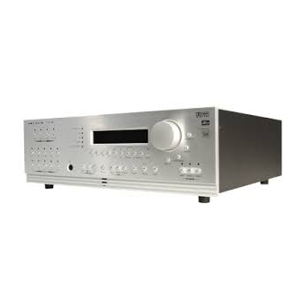
3. PANELS / DISPLAY/ REMOTE LAYOUT
3.1
FRONT PANEL LAYOUT
The front panel of the AVM 20 has the Master Control Knob, selection/navigation buttons, a display, status indicator LEDs, and
the Headphone jack .
1
18
17
1 – Path selection
2 – Mode / Surround Decoder indicators
3 – Display
4 – FM • AM Preset selection
5 – FM • AM Tuning / Setup Navigation
6 – Master Control Knob
• Volume
• Tune for FM • AM
• Setting Adjustment for Mode; DD Dynamics; THX
Options; Surround Mode Level / Bass / Treble /
Balance; Path Bass / Treble / Balance; Display
Brightness
• Setup Adjustment for Letters, Numbers, and Times
See section 5 for complete information on Front Panel operation.
11
2
3
16
15
4
14
13
7 – Surround Mode / Headphone settings for Level /
Bass / Treble / Balance
8 – Subwoofer / LFE Level settings
9 – Power On / Stand-By (MAIN / ZONE2 / ZONE3)
10 – Mute
11 – Status review / Setup (press and hold for 3 seconds)
12 – Balance setting
13 – Bass / Treble settings
14 – LED / Display Brightness setting (see section 7.4.10)
15 – Front Panel Remote Control IR Sensor
16 – Surround Mode / Dynamics / THX Options settings
17 – Headphone Jack
18 – Source selection
5
6
LOGIC
LOGIC
12
11
10
7
8
9
Advertisement
Table of Contents

Subscribe to Our Youtube Channel
Related Manuals for Anthem AVM 20


Summary of Contents for Anthem AVM 20
- Page 1 3. PANELS / DISPLAY/ REMOTE LAYOUT FRONT PANEL LAYOUT The front panel of the AVM 20 has the Master Control Knob, selection/navigation buttons, a display, status indicator LEDs, and the Headphone jack . LOGIC LOGIC 1 – Path selection 7 – Surround Mode / Headphone settings for Level / Bass / Treble / Balance 2 –...
- Page 2 3. PANELS / DISPLAY/ REMOTE LAYOUT continued … FRONT PANEL DISPLAY MAIN Display Example: 1 – Source selection (see section 5.4). 2 – Audio Input Format (see section 7.4.5) or Sleep Indicator if engaged (see section 6.5). 3 – Path that the information on the display refers to (see section 5.2). 4 –...
- Page 3 REAR PANEL LAYOUT The rear panel of the AVM 20 contains all connections, such as power connection, audio and video inputs and outputs, antenna connections, and the RS-232 port which allows software upgrades and external control of the AVM 20.
- Page 4 2 – Transmission Indicator LED (red) 3 – Power ON when in MAIN, ZONE2, or ZONE3 personality Power ON/OFF for other components (see #4) Note: This does not turn the AVM 20 off (see #31) SSP PATH MAIN 4 – Path / Component ‘Personality’ selection 5 –...
Need help?
Do you have a question about the AVM 20 and is the answer not in the manual?
Questions and answers