
Related Manuals for Agilent Technologies 8922M


Summary of Contents for Agilent Technologies 8922M
- Page 1 User’s Guide Agilent Technologies 8922M/S GSM Test Set Agilent Part No. 08922-90211 Printed in UK January 1998...
- Page 2 © Copyright 1998, Agilent Technologies. All rights reserved. No part of this manual may be reproduced in any form or by any means (including electronic storage and retrieval or translation into a foreign language) without prior agree- ment and written consent from Agilent Technologies Inc. as governed by United States and international copyright...
-
Page 3: Table Of Contents
Fuses and Power Cords ..............1-3 Installation Overview ................ 1-5 General Information................1-8 2 Making Measurements Using This Chapter ................2-2 Agilent Technologies 8922M/S Operating Modes ......2-3 ACTIVE CELL.................. 2-5 TEST MODE ..................2-9 CW GENERATOR ................2-12 Measurements .................. 2-13 If You Have Problems with a Measurement ........ - Page 4 Contents 4 Screens Field Types ..................4-2 Audio ....................4-4 Bit Error .................... 4-8 Bit Error 2 ..................4-11 Cell Configuration - GSM 900 ............4-16 Cell Configuration - E-GSM, DCS 1800, PCS 1900 ..... 4-22 Cell Control - Active Cell ............... 4-27 Cell Control - Active Cell + ............
- Page 5 Contents Pwr Ramp, Fall Edge ..............4-99 Pwr Ramp: Summary ..............4-101 Pwr Ramp: Pulse (Option 006 Only) ..........4-104 Pwr Ramp: Pulse Rise (Option 006 Only) ........4-107 Pwr Ramp: Pulse Fall (Option 006 Only) ........4-109 RF Generator / RF Analyzer (AF Gen) ........4-111 RF Generator / RF Analyzer (RF Analyzer) .........
- Page 6 Contents 6 Connectors Front-Panel Connectors of the Agilent Technologies 8922M/S ..6-2 Rear-Panel Connectors of the Agilent Technologies 8922M/S..6-10 Signal Descriptions for SYSTEM BUS ......... 6-18 Timing Diagrams................6-27 7 Messages Communication Failures ..............7-2 Firmware Error ................. 7-3 Sync Status ..................
- Page 7 A APPENDIX A Purpose ..................... A-2 Equipment Required ................. A-3 Connecting the Agilent 8922M to the HP/Agilent 37900D ..... A-4 Setting Up the Agilent Technologies 8922M ........A-5 Setting Up the HP/Agilent 37900D ..........A-6 How to Obtain a Protocol Log............A-8 Additional Information ..............
- Page 8 Contents Contents-6...
- Page 9 This Agilent Technologies instrument product is warranted against defects in material and workmanship for a period of one year from date of shipment. During the warranty period, Agilent Technologies will at its option, either repair or replace products which prove to be defective.
- Page 10 Assistance Product maintenance agreements and other customer assistance agreements are available for Agilent Technologies products. For any assistance, contact your local Agilent Sales and Service Office. For a list of contact information, see “Sales and Service Offices” on page ix.
- Page 11 THIS MATERIAL, INCLUDING, BUT NOT LIMITED TO, THE IMPLIED WARRANTIES OF MERCHANTABILITY AND FITNESS FOR A PARTICULAR PURPOSE. Agilent Technologies inc. shall not be liable for errors contained herein or for incidental or consequential damages in connection with the furnishing, performance or use of this material.
- Page 12 Electromagnetic Compatibility (EMC) Information Electromagnetic Compatibility (EMC) Information This product has been designed to meet the protection requirements of the European Communities Electromagnetic Compatibility (EMC) directive: EN55011:1991 (Group 1, Class A) EN50082-1:1992 - IEC 1000-4-2 (1995) ESD - IEC 1000-4-3 (1995) Radiated Susceptibility - IEC 1000-4-4 (1995) EFT In order to preserve the EMC performance of this product, any cable which becomes worn or damaged, must be replaced with the same type and specification.
-
Page 13: Declaration Of Conformity
Declares that the product GSM MS Test Set Product Name Model Numbers: Agilent Technologies 8922M and 8922S Product Options: This declaration covers all options of the above products as detailed in TCF A-5951-9852-02 Conforms with the protection requirements of European Council Directive 89/336/EEC on the approximation of the laws of the member states relating to electromagnetic compatibility. -
Page 14: Safety Information
Failure to comply with these precautions or with specific warnings elsewhere in this manual violates safety standards of design, manufacture, and intended use of the instrument. Agilent Technologies Inc. assumes no liability for the customer’s failure to comply with these requirements. - Page 15 Safety Information DO NOT OPERATE IN AN EXPLOSIVE ATMOSPHERE Do not operate the instrument in the presence of flammable gases or fumes. DO NOT REMOVE THE INSTRUMENT COVER Operating personnel must not remove instrument covers. Component replacement and internal adjustments must be made only by qualified service personnel. Instruments that appear damaged or defective should be made inoperative and secured against unintended operation until they can be repaired by qualified service personnel.
- Page 16 Safety Symbols Safety Symbols The following symbols on the instrument and in the manual indicate precautions which must be taken to maintain safe operation of the instrument Safety Symbols The Instruction Documentation Symbol. The product is marked with this symbol when it is necessary for the user to refer to the instructions in the supplied documentation.
-
Page 17: Sales And Service Offices
Sales and Service Offices Any adjustment, maintenance, or repair of this product must be performed by qualified personnel. Contact your customer engineer through your local Agilent Technologies Service Center. You can find a list of local service service representatives on the web at: http://www.agilent-tech.com/services/English/index.html... - Page 18 (tel) 1 800 452 488 In any correspondence or telephone conversations, refer to the power sensor by its model number and full serial number. With this information, the Agilent Technologies representative can quickly determine whether your unit is still within its warranty period.
-
Page 19: Agilent Technologies 8922M/S Documentation Description
Agilent 8922M/S GSM Test Set Performance Test Software. This 3.5 inch floppy disk allows you to verify the performance of the Agilent 8922. Instructions on how to use this are detailed in the Agilent 8922M/S GSM Test Set User’s Guide. -
Page 20: Typeface Conventions
Display text is used to show examples, fields, and prompts that are Display displayed on the Agilent 8922M/S screen. PRESET Keycaps on the Agilent 8922M/S keyboard are enclosed in boxes. Soft keys Display text is used to show examples, fields, and prompts that are displayed on the Agilent 8922M/S screen. -
Page 21: Installing Your Agilent 8922M/S
Installing Your Agilent 8922M/S... -
Page 22: Using This Chapter
8922M/S out of the box and for any other instrument moves. NOTE: If you have the Agilent 8922M/S Option 010 Multi-Band Test System, refer to the appropriate Agilent 8922 Multi-Band User’s Guide for more information on connection and operating differences. -
Page 23: Fuses And Power Cords
Line Voltage and Verify that the line voltage selection card is matched to the power source Fuse Selection (see Figure 1-1 on page 1-3). Order fuse Agilent part 2110-0083 (2.5 A 250 V, normal blow) for replacement. Figure 1-1 Voltage Selection Card and Fuse Installation Other Fusing Non user replaceable fusing on the secondary of this instrument power supply are;... - Page 24 Installing Your Agilent 8922M/S Fuses and Power Cords Power Cords Agilent Part Agilent...
-
Page 25: Installation Overview
1 Connect a 1, 2, 5, 10, or 13 MHz signal to the REF IN. If you are using option 001, connect as shown, see Figure 1-2 on page 1-5, with the supplied cable (OPT 001 REF OUT to REF IN). 2 Connect the supplied power cord to the Agilent 8922M/S and power up the instrument. Power Source... - Page 26 Installing Your Agilent 8922M/S Installation Overview 3 Access the CONFIG screen to customize the set-up of your Agilent 8922M/S. This is done by: • Moving to the CONFIG field in the bottom right-hand corner of the Cell Control screen, (the first screen that appears after power-up or after selecting PRESET ).
- Page 27 4 To guarantee the correct operation of the Agilent 8922M/S with all mobile phones, you should use a high-stability timebase. This step details how to configure the Agilent 8922M/S for use with either the option 001, high-stability timebase, or an external reference signal.
-
Page 28: General Information
Installing Your Agilent 8922M/S General Information General Information Operation and Refer to General Specifications in the Agilent 8922M/S Specifications section of Storage Chapter 3, Performance Verification for information about the operation or storage Environment environment. Instrument Options Refer to Agilent 8922M/S Specifications in Chapter 3, Performance Verification for information about instrument options. -
Page 29: Making Measurements
Making Measurements... -
Page 30: Using This Chapter
Making Measurements Using This Chapter Using This Chapter Use this chapter to obtain an overview of how to operate the Agilent 8922M/S GSM Test Sets. This chapter is divided into the following sections: • Making Measurements • Agilent 8922M/S Operating Modes - explains how to configure the Agilent 8922M/S so that measurements can be made. -
Page 31: Agilent Technologies 8922M/S Operating Modes
CW GENERATOR Active Cell The first mode is the default mode and configures the Agilent 8922M/S as a GSM Base Station emulator. This allows calls to be made from the Agilent 8922M/S to the mobile phone and vice versa. Measurements can then be made to verify the mobile phone’s performance. - Page 32 Making Measurements Agilent Technologies 8922M/S Operating Modes To configure the Agilent 8922M/S to the desired operating mode, carry out the following instructions, referring to Figure 2-1 on page 4 for the position of the fields. • Ensure (1) is set to mobile phone type you require (GSM900, E-GSM, DCS1800, or PCS1900).
-
Page 33: Active Cell
Connect the mobile phone to the RF IN/OUT connector on the front panel of the Agilent 8922M/S. • Switch on the mobile phone and wait for it to camp to the Agilent 8922M/S (most mobile phones display 001-01 when the mobile phone has camped). •... - Page 34 Active Cell Mode Making a Call From To call (or page) the mobile phone from the Agilent 8922M/S, it is necessary for the the Agilent 8922M/S Agilent 8922M/S to know the number of the SIM in the mobile phone. [This number to the Mobile Phone is the International Mobile Subscriber Identity (IMSI).
- Page 35 8922M/S and the mobile phone. For additional information on valid Absolute RF Channel Numbers (ARFCNs), consult the specifications in Chapter 3. TX Level This is a coded number used by the Agilent 8922M/S to command the mobile phone to transmit at a particular power. When the TX Level is changed, two things happen: •...
- Page 36 The two most likely are that, either, the mobile phone is not operating correctly, or, there is some power loss between the Agilent 8922M/S RF IN/OUT connector and the mobile phone. If you suspect it is the second case, you can compensate the Agilent 8922M/S generator settings and measurement results for external losses or gains.
-
Page 37: Test Mode
Making Measurements TEST MODE TEST MODE To enter this mode, select TEST MODE as described in the section titled “Agilent 8922M/S Operating Modes”. In TEST MODE, the Agilent 8922M/S no longer controls the mobile phone. The TEST MODE is used when it is not desired, or not possible, to set up a call between the Agilent 8922M/S and the mobile phone. - Page 38 Making Measurements TEST MODE NOTE While the Test Mode is selected, the three MEASURE ON parameters are also available on the bottom right-hand side of all measurement screens. This provides control of the Expected Input parameters during measurements. Figure 2-3 Test Mode Mobile Phone To measure an incoming signal from the mobile phone’s transmitter, perform the...
- Page 39 Broadcast Channel (BCH), by varying the BCH number and amplitude, (4), Using Test Mode see Figure 2-3 on page 2-10. TEST MODE provides the Agilent 8922M/S with a “forced” traffic channel (TCH) generator which can be turned on and off without the need for any signaling or the presence of a mobile phone.
-
Page 40: Cw Generator
CW GENERATOR To enter this mode, select CW GENERATOR as described in the section titled “Agilent 8922M/S Operating Modes”. The CW Generator mode has the same measurement capabilities as the Test Mode but replaces the GSM BCH and forced TCH signals with a single unmodulated RF carrier. The frequency and amplitude of the Continuous Wave (CW) signal is controlled by the Channel, Amplitude, and the Frequency fields (1). -
Page 41: Measurements
Making Measurements Measurements Measurements The measurements available on the Agilent 8922M/S can all be accessed from the cell control screen by selecting a measurement field under MEASUREMENTS, (see Figure 2-5 on page 2-13) and pushing the knob. GSM Specific The measurements available are: Measurements •... - Page 42 Method The peak transmitter carrier power value is displayed on the cell control screen. After you have set up a call (Active Cell) or manually aligned the Agilent 8922M/S to the mobile phone (Test Mode/CW Generator), the Peak Power reading is displayed in the center of the screen (1).
- Page 43 The measurement fields in this screen are RMS Phase Error, Peak Phase Error and Frequency Error (1), see Figure 2-7 on page 2-15. The Agilent 8922M/S input sensitivity (2) can be varied, if necessary, to ensure that the input signal level matches the Agilent 8922M/S RF Analyzer. Valid measurements are only made when the signal is within 3 dB of the RF Analyzer setting.
- Page 44 Making Measurements Measurements These are: • PHASE ERR - this displays the phase error graphically. The phase error trace is displayed using an autoscaling phase error axis versus data bits (numbered 0 through 147). • DATA BITS - this screen allows you display a screen which details the values of the 148 bits in the timeslot (including midamble).
- Page 45 12 time fields. You can choose your own time-positions, or use the default settings. The sensitivity of the Agilent 8922M/S receiver can be varied (3) allowing you to verify whether the input signal level matches the Agilent 8922M/S RF Analyzer.
- Page 46 (1), see Figure 2-9 on page 2-18 • The sensitivity of the Agilent 8922M/S receiver can be varied (2) allowing you to verify whether the signal still falls within the boundaries of the GSM power mask.
- Page 47 Data bits that are decoded are sent back to the Agilent 8922M/S. The Agilent 8922M/S compares them to original signal that was sent out and the differences are derived from this.
- Page 48 Making Measurements Measurements By varying the Base station Amplitude field (4), you can test the mobile phone’s receiver sensitivity. Actual results can be compared with the values reported by the radio. NOTE If the Base Station amplitude is lowered too much, the radio will lose the call. This will need to be re-established by increasing the base station amplitude, returning to the cell control screen, and originating the call before you can continue measurements.
- Page 49 Making Measurements Measurements This sets the reference level to which the offset frequency values are compared. • Select Ramping or Modulation (3). • Set your Freq Offset value (4). Figure 2-11 Output RF Spectrum Measurements • The trace of the output RF spectrum can be viewed if you highlight View and select Trace (5).
- Page 50 Making Measurements Measurements In the Agilent 8922, Output RF Spectrum measurements are made using a 3-pole synchronously tuned measurement filter. The measurement results will differ from measurements using a 5-pole filter. The difference between measurements of the “ideal” signals using a 3-pole filter and a 5-pole filter are shown in Table 1 and Table 2.
- Page 51 Making Measurements Measurements Table 3 Adjusted Limits Based on 3-Pole Filter Output RF Spectrum Due to Modulation Power Offset from Carrier (kHZ) Control 600 to Level 1800 0 (43 dBm) 0 dB 0.5 dB -32 dB -51 dB -70 dB -27.5 0 (39 dBm) -27.5...
- Page 52 Figure 2-12 on page 2-25. • RF Gen - this controls the RF generator in the Agilent 8922M/S. The generator signal can be fed back into the spectrum analyzer for signal confirmation. The Aux RF OUT port should be connected to the RF In/Out, and the RF Output set to “Aux RF OUT”.
- Page 53 Figure 2-12 Spectrum Analyzer Measurement Use the MeasReset (2) to reset the trace and measurements in the Agilent 8922M/ S. This is useful if you are using the Max Hold field (3). The resolution bandwidth of the spectrum analyzer is automatically coupled to the frequency span.
- Page 54 Figure 2-13 Oscilloscope Measurements Use the MeasReset (2) to reset the trace and measurements in the Agilent 8922M/ S. This is useful for single triggered measurements. Set AF Anl In (3) to change the source of the signal being directed to the Audio Analyzer Input.
- Page 55 Anl In (5), see Figure 2-14 on page 2-27. Select AUDIO in the cell control screen to gain access to the audio function of the Agilent 8922M/S. The measurements of the audio voltage and frequency commence within a short time of the screen being accessed.
- Page 56 CWFreqErr from field 1. Figure 2-15 CW Measurements These measurements can be reset using MeasReset. Select Pwr Zero before power is applied to zero the power meter in the Agilent 8922M/S. 2-28...
- Page 57 Making Measurements Measurements NOTE Although CW Measurements is a broadband measurement, it uses calibration data that relies on the expected input frequency being set correctly. The Power Detector is connected so that it will only make measurements on signals present at the RF In/ Out port.
-
Page 58: If You Have Problems With A Measurement
Making Measurements If You Have Problems with a Measurement If You Have Problems with a Measurement This section tells you what to do if either of the following screen display events occurs: • Message Line Messages (on the top of the screen). •... - Page 59 Making Measurements If You Have Problems with a Measurement Figure 2-16 2-31...
- Page 60 Making Measurements If You Have Problems with a Measurement Possible Solutions to The signal processing hardware that is used to generate measurement results has to Message Line Errors be told when to take data samples. If the trigger to do this is misaligned with the signal, there may be errors in the results that are displayed.
- Page 61 Making Measurements If You Have Problems with a Measurement Trigger Range For Pulsed RF 2-33...
- Page 62 Making Measurements If You Have Problems with a Measurement Is an Error Message The sync status field displays an error message for the following errors: Displayed in the • Bad Sync - demodulation error, perform a Phase/Frequency error measurement Sync Status field? to identify which of the Sync Status error listed below may be the possible problem.
- Page 63 Making Measurements If You Have Problems with a Measurement Possible Solutions to Solution 1 - Trigger Timing Sync Status Errors Check if the trigger is being received. On the MEAS SYNC screen (press to gain access), check if the MEAS SYNC correct burst type has been defined.
- Page 64 Making Measurements If You Have Problems with a Measurement Solution 2 - Midamble Sync On the MEAS SYNC screen (press to gain access), MEAS SYNC • Check the definition of the signal’s burst type (A). • Check the Burst Sel field (B). Check the bit pattern of your measurement Perform a Data Bits measurement (D).
- Page 65 Making Measurements If You Have Problems with a Measurement Solution 3 - Level Check the following fields on the RF Generator/RF Analyzer screen (press SHIFT CELL CNTL , (RFG/RFA) to gain access). 3 Pulse field (a), (if signal is pulsed) Ext or Hop Trig should be selected. 4 Amplitude field (b), for the expected amplitude 5 Frequency field (c), for the correct frequency.
- Page 66 Making Measurements If You Have Problems with a Measurement Solution 4 - Amplitude Envelope • Check if the Pulse Amplitude is 1 dB of the expected value during the useful part of the burst. If FM Errors: Perform a Phase Freq:Data Bits measurement. Dashes (a) will display under the bits where the power is too low.
-
Page 67: Advanced Features
• Configuration - the configuration screen is a full instrument control screen which allows you to set up the Agilent 8922M/S. Screen set up, compatibility mode, radio type as well as other miscellaneous pieces of information are contained on this screen. To access this screen, highlight More and select CONFIG. - Page 68 Trigger Delay is not automatically restored. Example: In the Agilent 8922M/S, when using the RF Rise, a Trig- ger Delay of 0 is recommended. When changing from RF Rise to Ext Demod trigger mode, the default value of 473.4T should be re-entered for Trigger Delay.
- Page 69 Making Measurements Advanced Features Power Ramp Setting The mobile transmitter output ramp should settle so that it complies with the power Time mask (GSM Rec 11.10) by the time output level calibration is done in the manufacturing process. The power mask is displayed in the Power Ramp screens. Peak Carrier Power measurement method is not made to GSM Rec.
- Page 70 GSM Rec. 11.10. Making There are two ways of making a synchronized external measurement using triggers Synchronized from the Agilent 8922M/S: External 1 Use the G_EXT_TRIG on the rear panel SYSTEM_BUS connector. See Measurements Using Chapter 6, Connectors for a pin out diagram.
- Page 71 MEAS_TRIG_OUT signal on the rear panel SYSTEM_BUS connector. The trigger is only generated when a measurement is being made. This signal may be used to trigger an externally connected measurement device such as the HP/Agilent 71150/250 GSM high performance spectrum analyzers. 2-43...
- Page 72 SAME. The SAME mode means “the same paging mode as last indicated.” 4 TMSI reallocation in the Agilent 8922M/S uses the two (2) octet TMSI size. 5 The Agilent 8922M/S does not turn off the transmitter during DTX when the voice activity detector (VAD) determines that there is no speech input present.
- Page 73 64. It is difficult to recover from this state without ending the call with the mobile. Changing back to EXT_DEMOD triggering will cause the call to drop. This is because the Agilent 8922M/S is listening for the mobile 64 bits later than the RF Rise triggering left it.
- Page 74 Making Measurements Advanced Features 12 Some measurement results may be displayed as ---- due, for example, to mobile failure. The measurement has been armed but has not completed. In these circumstances a GPIB query of the measurement will not return a result. This event should be catered for by adding a time-out to the query and a “CLEAR”...
- Page 75 Making Measurements Advanced Features 2-47...
-
Page 76: Verifying Performance
Verifying Performance... -
Page 77: About This Chapter
About This Chapter About This Chapter The tests in this chapter verify the electrical performance of the Agilent 8922M/S GSM Test Set using the Agilent 8922 Performance Test Software provided with the product. If the instrument passes this verification, its operation and specifications are assured within the measurement uncertainties provided in the performance test print out. -
Page 78: Setting Up The Tests
Required Test Equipment lists the test equipment needed for the performance Test Equipment tests. This is the only equipment supported by the Agilent 8922 Performance Test Software and is required to verify instrument operation. Equipment substitutions or manual performance tests are not recommended or supported by Agilent Technologies. -
Page 79: Getting The Right Equipment
Getting the Right Equipment The following equipment is required to do all of the performance tests. The test descriptions have an equipment list that specifies the equipment used for each particular test. Equipment HP/Agilent Model Number Measuring Receiver 8902A Sensor Module 11722A... -
Page 80: Installing And Operating The Software
“Using the Compatibility Switch - Forward Conversion”. Using the Back Conversion Compatibility To turn the instrument from the Agilent 8922M/S back to an Agilent 8922G or an Switch Agilent 8922E, select the following keys: • CONFIG (this is accessible from the Cell Control screen in the bottom right-hand corner). - Page 81 Verifying Performance Installing and Operating the Software Forward Conversion To return the instrument from an Agilent 8922G back to an Agilent 8922M or an Agilent 8922E to an Agilent 8922S, select the following keys: • More (this is accessible from the Cell Control screen in the bottom right-hand corner).
-
Page 82: Understanding The Tests
HP/Agilent 8902A. • Low level signals from the Agilent 8922M/S must be very stable to be measured by the tuned RF level function of the HP/Agilent 8902A. The instrument timebases should be locked together. Also, if the Agilent 8922 source has unusually high residual FM it may cause the low level measurements to fail because the HP/Agilent 8902A cannot lock onto the signal. - Page 83 30 dB and 80 to 90 dB. Rise time and fall time for each of these is measured. When the Agilent 8922S is the UUT, the RF Generator is set to generate a pulsed GMSK signal. This signal is then analyzed with the UUT detector and oscilloscope.
- Page 84 This signal is then analyzed by the UUT to assure that the frequency and phase errors are correct. If the UUT is an Agilent 8922S, clock and data signals are generated internally, and the HP/Agilent 8904A is not used.
- Page 85 HP/Agilent 3456AVoltmeter Theory of the Test The HP/Agilent 8904A is used to generate accurate test signals which are analyzed by the UUT. The voltmeter is used to reduce measurement uncertainty by accurately characterizing the test signal level to predict the correct response of the UUT. The voltmeter is used in the AC level, DC level, SINAD and distortion measurements.
- Page 86 The actual measurements are compared to the predicted to determine the accuracy of the UUT. The HP/Agilent 8904A is also used to create the 270.833 kHz clock signal and the pulse generator is used to create a random data pattern.
- Page 87 Test A: RF Analyzer Equipment Required Pulse Demodulation HP/Agilent 8657A/B Signal Generator HP/Agilent 8116A Pulse Generator Theory of the Test The Pulse generator drives the signal generator to generate Pulsed RF signals at various frequencies. The UUT demodulates these signals and the internal oscilloscope measures the rise and fall time of the demodulated waveform.
-
Page 88: Understanding Test Failures
Understanding Test Failures Understanding Test Failures This section is intended to be used in conjunction with the Agilent 8922 Series Assembly Level Repair Guide for assembly level repair and troubleshooting. If a performance test fails and hardware is suspected, the following table is a guideline to help identify the hardware assemblies most likely to cause each failure. -
Page 89: Agilent Technologies 8922M/S Specifications
Agilent Technologies 8922M/S Specifications Agilent Technologies 8922M/S Specifications NOTE: If you have the Agilent 8922M/S Option 010 Multi-Band Test System, refer to the appropriate Agilent 8922 Multi-Band User’s Guide for more information on specifications relevant to dual band testing. GSM900 and... - Page 90 Verifying Performance Agilent Technologies 8922M/S Specifications Supplemental Characteristics: To 1015 MHz with uncalibrated output and modulation Frequency Overrange 577 s over the GSM frequency bands in hop mode (refer to 0.3 Switching Speed GMSK modulation specs Output RF In/Out Connector...
- Page 91 Frequency Error [0.02 ppm (18 Hz) + reference accuracy], for normal bursts Typically [0.03 ppm (27 Hz) + reference accuracy], for RACHs. Amplitude Flatness 0.25 dB peak. Clock Input (Agilent 8922M only) Frequency 270.833 kHz 2 Hz (relative to reference). Level Data Input (Agilent 8922M only) Non differentially encoded input.
- Page 92 Verifying Performance Agilent Technologies 8922M/S Specifications 30 dB Pulse Modulation (Agilent 8922M only) All timeslots 30 dB higher than desired/active timeslot, to test adjacent timeslot rejection. Supplemental Characteristics: Input Levels Rise/Fall Time (10 to 90%) AM for Level Control (Agilent 8922M Only)
- Page 93 Verifying Performance Agilent Technologies 8922M/S Specifications RF Analyzer Frequency Specifications Range 10 MHz to 1 GHz Resolution 1 Hz Hop Mode 100 kHz Resolution Offset Frequency 50 kHz 1 Hz Offset Resolution RF In/Out SWR <1.5:1 Supplemental Characteristics: To 1015 MHz...
- Page 94 Verifying Performance Agilent Technologies 8922M/S Specifications Peak/Transmitter Carrier Power Measurement RF In/Out only. After one timeslot, 577 s, from an isolated Receiver Hop Trigger in the GSM bands. Range -5 to +41 dBm Input Frequency Setting Error 10 kHz Input Level Setting Error...
- Page 95 Verifying Performance Agilent Technologies 8922M/S Specifications Accuracy (ON/OFF 40 dB, RF In/Out only) OFF Power (dBm) ON/OFF Ratio Accuracy 30 to 1 2.4 dB 1.1 typically 37 to 30 2.9 dB 1.3 typically 42 to 37 3.7 dB 1.7 typically 47 to 42 4.2 dB...
- Page 96 [0.01 ppm (9 Hz) + reference accuracy], for normal bursts. [0.02 ppm (18 Hz) + reference accuracy] for RACH bursts. 0.3 GMSK Data Recovery (Agilent 8922M only) After one timeslot, 577 s, from an isolated Receiver Hop Trigger in the GSM...
- Page 97 Verifying Performance Agilent Technologies 8922M/S Specifications FM Demodulation Output (Agilent 8922M only) Range RF In/Out 6 to +41 dBm Aux RF In 36 to +20 dBm Sensitivity 20 V/Hz 5% (into an open circuit) Input Frequency Setting Error 50 kHz, with 100 kHz pk deviation...
- Page 98 Verifying Performance Agilent Technologies 8922M/S Specifications Output RF Spectrum Measurement (Requires Option 006) After one timeslot, 577 s, from an isolated Receiver Hop Trigger in the GSM Frequency bands. Range RF In/Out 6 to +41 dBm Aux RF In 36 to +20 dBm...
- Page 99 Verifying Performance Agilent Technologies 8922M/S Specifications Spectrum Analyzer Specifications (Option 006) Frequency Range 10 MHz to 1 GHz Frequency Span/Resolution Span Bandwidth Bandwidth (coupled) <50 kHz 300 Hz <200 kHz 1 kHz <1.5 MHz 3 kHz 30 kHz 4 MHz...
- Page 100 Verifying Performance Agilent Technologies 8922M/S Specifications Audio Source Frequency Specifications Range DC to 25 kHz Accuracy 0.025% of setting Supplemental Characteristics 0.1 Hz Minimum Resolution Output Level Range 0.1 mV to 4 V Maximum Output Current 20 mA peak Output Impedance <1...
- Page 101 Verifying Performance Agilent Technologies 8922M/S Specifications AC Voltage Measurement Voltage Range 0 V to 30 V Accuracy (20 Hz to 15 kHz), Input >1 mV 3% of reading Residual Noise + THD (15 kHz BW) 175 V Supplemental Characteristics 2 Hz to 100 kHz...
- Page 102 Verifying Performance Agilent Technologies 8922M/S Specifications Audio Filters There are seven filters used in the Agilent 8922M/S. • 50 Hz HPF • 300 Hz HPF • 300 Hz LPF • 3 kHz LPF • 15 kHz LPF • 750 s de-emphasis •...
- Page 103 Verifying Performance Agilent Technologies 8922M/S Specifications Remote Programming GPIB IEEE Standard 488.2 Functions Implemented SH1, AH1, T6, L4, SR1, RL1, LE0, TE0, PP0, DC1, DT1, C4, C11, E2 RS-232 3 wire RJ-11 connector used for serial data in and out.
- Page 104 Operating This instrument is designed for indoor use only. Environment If the instrument is subjected to Agilent Class B condensation, it is recommended that the instrument be powered up for at least 30 minutes before normal operation. CAUTION This instrument is designed for use in Installation Category II and Pollution Degree 2 per IEC 1010 and 644 respectively.
- Page 105 Verifying Performance Agilent Technologies 8922M/S Specifications Reference The accuracy needs for testing GSM radios require the unit to be operated with the Specifications High Stability Reference (Option 001) or an external high stability reference. Accuracy (after warm up) [(Time since calibration...
- Page 106 Verifying Performance Agilent Technologies 8922M/S Specifications 3-31...
- Page 107 Screens NOTE If you have the Agilent 8922M/S Option 010 Multi-Band Test System, refer to the appropriate Agilent 8922 Multi-Band User’s Guide for more information on additional screens and screen differences.
-
Page 108: Field Types
Screens Field Types Field Types 1. Alphanumeric This field is where you enter names or titles. To enter, position the cursor next to a character or edit function, then push the knob to select it. (A list of character and function choices appears in the bottom-right corner of the screen.) 2. - Page 109 Screens Field Types 4. Underlined Entry This type of field allows selection between the two labels in the field separated by a slash (/). To toggle between the choices, position the cursor next to the field and push the knob. The underlined choice is activated. 5.
-
Page 110: Audio
Screens Audio Audio 1. AC Level This field displays the measured ac level of the AF analyzer input (AF Anl In) when Audio Out, Pls Demod, Audio In, Speech In, Speech Out, or Scope In is selected as the input. See Also Keys: ON/OFF, HI LIMIT, LO LIMIT, REF SET, AVG, METER, Units... - Page 111 Audio Out selects the signal going to the AUDIO OUT front- panel connector. NOTE The AM Mod In and the Speech In are not featured in the Agilent 8922S. 4. Amplitude This field is the AF Generator Audio Out amplitude setting.
- Page 112 OFF allows the audio signal/tone level to determine the speaker output. NOTE Speaker ALC is not featured in the Agilent 8922S. 12. Speaker Vol This field turns the Speaker Volume off or directs control to the front-panel volume control.
- Page 113 Echo causes the Agilent 8922M/S to send back the received speech signal to the mobile station. The echo delay is the additional delay the Agilent 8922M/S inserts before sending back speech to a mobile station. PRBS generates a pseudo random bit sequence which is used for making bit error tests.
-
Page 114: Bit Error
Screens Bit Error Bit Error 1. Amplitude (Base This field changes the RF generator amplitude. It is a duplicate of the RF generator’s Station) Amplitude field on the RF Generator/RF Analyzer screen. See Also Screens: RF Generator/RF Analyzer (RF Generator). 2. - Page 115 In normal BER mode, the loop delay is the total Round Trip Delay (RTD) of the Agilent 8922M/S and mobile phone, expressed in speech frames. The correct number of TDMA frames can be determined automatically by making a Bit Error Test using Auto Mode when the bit error ratio is approximately <20%.
- Page 116 Screens Bit Error 12. Res Type Residual Type field selects the type of bit error test results to display. (Res means (Measure) residual). Choices TypeIa ResTypeIa TypeIB ResTypeIB TypeII ResTypeII TypeI ResTypeI AllFS ResAllFS 13. Run/Stop Run starts a bit error test. Stop discontinues the bit error test in progress. (Control) 14.
-
Page 117: Bit Error 2
Screens Bit Error 2 Bit Error 2 Each time the Bit Error Test is run, four measurements are made (see Meas Num). Because of limited screen space, only two measurements are displayed at one time. The upper left side of the screen will display measurement 1 or 3, and the upper right side will display measurement 2 or 4. - Page 118 Screens Bit Error 2 NOTE This field is not featured in the Agilent 8922S. 2. Amplitude This field changes the RF generator amplitude. It is a duplicate of the RF generator’s Amplitude field on the RF Generator/RF Analyzer screen. See Also Screens: RF Generator/RF Analyzer (RF Generator).
- Page 119 These fields select the loopback mode for the mobile station. When one of these fields is selected, the Agilent 8922M/S will attempt to put the mobile station in the described loopback mode. The mobile station must be on a traffic channel to receive the loopback message.
- Page 120 Screens Bit Error 2 18. 0.0 (Reference) This field is used to adjust the reference offset when using the tunable reference. 19. Count or Ratio This field determines how the frame erasures or cyclic-redundancy-check (CRC) errors will be displayed. Choices Count displays the number of frame erasures or cyclic- redundancy-check (CRC) errors.
- Page 121 This field is used to enter or display amount of delay (expressed in number of speech frames), before bits are compared. The Agilent 8922 uses this value to synchronize to the correct received PRBS speech frame. The correct number of speech frames can be determined automatically by making a Bit Error Test using Auto Mode when the bit error ratio is approximately <20%.
-
Page 122: Cell Configuration - Gsm 900
Cell Configuration - GSM 900 Cell Configuration - GSM 900 1,17 Activated When Activated is displayed, the Agilent 8922M/S is operating as a base station simulator, and calls can be attempted. Most settings affecting cell configuration are not settable (cannot be changed) while Activated. - Page 123 Screens Cell Configuration - GSM 900 Field State RF Gen, Hop Trig RF Anl, Hop Trig check setting Hop Address, Address Source RF Gen, Settling Normal RF Analyzer, Settling Normal RF Gen, Hop Mode RF Analyzer, Hop Mode check setting RF Analyzer, Hop Frequencies Address RF Generator, Hop Frequencies Address Hop Address...
- Page 124 NOTE The data output includes a midamble, which will result in discrete sidebands. If random data is desired, use an HP/Agilent 8904A Option 001 or 002 to generate random data and clock signals to the 0.3 GMSK generator. See Also...
- Page 125 Screens Cell Configuration - GSM 900 8. Control Ch This field selects the control channel organization. Choices SD/4 selects a broadcast channel with a BCCH + CCCH + SDCCH/4 channel organization. The broadcast channel will be on the physical channel defined under the Serv Cell ARFCN field, timeslot 0.
- Page 126 Screens Cell Configuration - GSM 900 11. MA2 This field is a 64-element Boolean array that defines which cell- allocation absolute radio frequency channel numbers (CA ARFCNs) will be in mobile allocation number 2 (MA2). MA2 defines which of the first 64 entries of 1s in the CA will be part of the sequential hop sequence for MA2.
- Page 127 This field, when Settable is displayed, indicates that all Cell Configuration settings can be set or modified. When the Agilent 8922M/S Cell Configuration is changed from Activated to Settable, some fields are automatically changed or overwritten. Use the following table to locate the fields that might affect your setup.
-
Page 128: Cell Configuration - E-Gsm, Dcs 1800, Pcs 1900
Cell Configuration - E-GSM, DCS 1800, PCS 1900 1. Activated When Activated is displayed, the Agilent 8922M/S is operating as a base station simulator, and calls can be attempted. Most settings affecting cell configuration are not settable (cannot be changed) while Activated. - Page 129 Screens Cell Configuration - E-GSM, DCS 1800, PCS 1900 Field State RF Gen, Hop Trig RF Anl, Hop Trig check setting Hop Address, Address Source RF Gen, Settling Normal RF Analyzer, Settling Normal RF Gen, Hop Mode RF Analyzer, Hop Mode check setting RF Analyzer, Hop Frequencies Address RF Generator, Hop Frequencies Address...
- Page 130 NOTE The data output includes a midamble, which will result in discrete sidebands. If random data is desired, use an HP/Agilent 8904A Option 001 or 002 to generate random data and clock signals to the 0.3 GMSK generator. See Also...
- Page 131 Screens Cell Configuration - E-GSM, DCS 1800, PCS 1900 8. Control Ch This field selects the control channel organization. Choices SD/4 selects a broadcast channel with a BCCH + CCCH + SDCCH/4 channel organization. The broadcast channel will be on the physical channel defined under the Serv Cell ARFCN field, timeslot 0.
- Page 132 This field, when Settable is displayed, indicates that all Cell Configuration settings can be set or modified. When the Agilent 8922M/S Cell Configuration is changed from Activated to Settable, some fields are automatically changed or overwritten. Use the following table to locate the fields that might affect your setup.
-
Page 133: Cell Control - Active Cell
Agilent 8922M/S. • Test Mode - this mode sets the Agilent 8922M/S to work with a mobile phone running a test mode. This mode allows you to transmit either BCCH only or BCCH and TCH and measures an independent GSM signal. - Page 134 • Alerting • Connected 6. Channel (Base This field selects which channel the Agilent 8922M/S transmits the Broadcast Station) Channel (BCCH) information. If this is changed during a call, the call will be deactivated. 7. CW Meas This field displays the CW measurements screen.
- Page 135 RF analyzer setting to match this input. When this field is changed, the mobile phone TX Level and the Agilent 8922M/S RF Analyzer are no longer coupled together. This means that you have independent control of the amplitude of the transmitted mobile phone signal and the sensitivity of the Agilent 8922M/S analyzer circuit.
- Page 136 (Mobile) This can be changed either before or during a call. Changing the value in this field re-couples the mobile phone’s output level to the Agilent 8922M/S’s Expected Input. If 0 (zero) is selected then an error message may appear which recommends using an external attenuator.
-
Page 137: Cell Control - Active Cell
Channel (TCH) and Colour Code of the expected signal. 3. Channel This field displays the channel number the Agilent 8922M/S is taking measurements from. For a GSM900 mobile phone the channel number may vary from 1 through 124. For an E-GSM mobile phone the channel number may vary from 0 through 124 and 975 through 1023. - Page 138 Cell Control - Active Cell + 5. Single/Hop This field selects whether communication between the Agilent 8922M/S and the mobile phone will be on one channel only or hopping across channels. The channels it will hop across is defined on the Cell Config screen. The channel field displays MA1 or MA2.
-
Page 139: Cell Control - Test Mode
Agilent 8922M/S. • Test Mode - this mode sets the Agilent 8922M/S to work with a mobile phone running a test mode. This mode allows you to transmit either BCCH only or BCCH and TCH and measures an independent GSM signal. - Page 140 Cell Control - Test Mode 3. Channel This field displays the channel number the Agilent 8922M/S is taking measurements from. For a GSM900 mobile phone the channel number may vary from 1 through 124. For an E-GSM mobile phone the channel number may vary from 0 through 124 and 975 through 1023.
-
Page 141: Cell Control - Cw Generator
Cell Control - CW Generator Cell Control - CW Generator This screens allows you to set the Agilent 8922M/S up as a CW Signal Generator. 1. Base Station There are two Base Station fields. The Amplitude field sets the amplitude of the Agilent 8922M/S transmission. - Page 142 Agilent 8922M/S. • Test Mode - this mode sets the Agilent 8922M/S to work with a mobile phone running a test mode. This mode allows you to transmit either BCCH only or BCCH and TCH and measures an independent GSM signal.
-
Page 143: Cell Control 2
Screens Cell Control 2 Cell Control 2 1. Adj Cell This field selects which adjacent cell SACCH measurement result to display. The adjacent cells are prioritized by power level. One is the largest signal. Range 1 to 6 2. Amplitude This field changes the RF generator amplitude. - Page 144 Connected • Disconnect • Proceeding 7. Call Status TCH These fields give information about the current TCH. (If the Agilent 8922M/S is not State on a TCH yet, these will be blank.) • Mode (Hopped or Single) • ARFCN (this will be an integer if TCH Mode is single, otherwise MA1 or MA2) •...
- Page 145 This field is set to Disarm whenever a measurement screen (Output RF Spectrum, Phase/Frequency or Pulse) is accessed. When Demod Arm is disarmed, the Agilent 8922M/S cannot display information about the uplink. When Demod Arm is re-armed, the Cell Control fields that display information about the uplink will resume normal operation.
- Page 146 TCH is the traffic channel. This is the normal operating mode. 17. Loopback These fields select the loopback mode for the mobile station. When one of these fields is selected, the Agilent 8922M/S will attempt to put the mobile station in the described loopback mode. Choices Off turns loopback mode off.
- Page 147 Screens Cell Control 2 19. MM This field displays the latest events from the Mobility Management sublayer. • Loc Upd • Ident • Auth • TMSI • Inactive • Active 20. Mode This field selects the mode for the traffic control channel selected in the TCH Parms field.
- Page 148 Cont pages continuously until a connection is made. 24. PRBS Pattrn This field allows you to choose from 6 different bit patterns. The Agilent 8922M/S will send the selected sequence to a mobile station. The mobile station must be in loopback mode (see Loopback field description) to return the bit sequence for bit...
- Page 149 The trigger delay’s default value of 473.4 T reflects an additional Agilent 8922M/S delay of 4.65 T (468.75 + 4.65 = 473.4 T). The accuracy of this measurement is 0.25 T. For more accurate measurements, refer to DSP Analyzer, Data Bits, First Bit.
- Page 150 Radio Resource sublayer. • BCCH indicates that a broadcast channel is being transmitted, and the Agilent 8922M/S is ready to receive a RACH. • DCCH indicates that a control channel is established. The physical channel organization depends on the Control Channel setting (see Cell Configuration screen).
- Page 151 Screens Cell Control 2 31. SACCH Meas These fields indicate the measurement results of a slow associated control channel measurement. • TX Lev indicates the mobile station’s reported transmitter power level. • Tim Adv is the mobile station’s reported timing advance. •...
- Page 152 Echo causes the Agilent 8922M/S to send back the received speech signal to the mobile station. The echo delay is the additional delay the Agilent 8922M/S inserts before sending back speech to a mobile station. PRBS generates a pseudo random bit sequence which is used for making bit error tests.
- Page 153 Cell Control 2 34. Speech Gain This field sets the amplification of the Cond speech mode. NOTE This field is not featured in the Agilent 8922S. 35. TCH Control This field selects traffic-channel control type. Choices TCH1 HO selects an intercell handover based on the TCH1 parameter selections.
- Page 154 Screens Cell Control 2 38. Timeslot This field selects the timeslot for the traffic channel selected in the TCH Parms field. Range 2 through 6 39. Timing Advance This field selects the timing advance mode. (mode) Choices Manual allows manual setting of the MS timing advance. When Manual is selected, the mobile station’s timing advance can be changed by entering a number in the Timing Advance (number) field.
-
Page 155: Configure
Screens Configure Configure 1. Aux RF In This field is used to indicate losses or gains between the AUX RF IN port and the device under test. NOTE This field is only used when the RF Level Offset field is set to On. Enter a positive value to indicate a gain (such as an amplifier). - Page 156 Quiet Loud 4. Compatible This toggle field allows you to simulate the operation of an Agilent 8922G (from an PRESET Agilent 8922M) or an Agilent 8922E (from an Agilent 8922S). The can be used to set the correct Preset conditions after this field has been changed, although a power cycle is recommended.
- Page 157 Screens Configure 8. I/O Config This field allows you to access the I/O configuration screen. This screen allows you to select your printer configuration, GPIB and serial port communication settings. 9. Meas Reset (Meas Selecting Meas Reset will erase any accumulated measurements used for calculating Cntl) a final result, and re-start the measurement process for the following functions: •...
- Page 158 Screens Configure 14. Reference This field selects the external reference frequency that the instrument locks to, and sets the reference tuning mode. Choices 13 MHz 10 MHz 5 MHz 2 MHz 1 MHz Normal locks the instrument to the external reference frequency selected.
- Page 159 Screens Configure 17. RF Level Offset This field enables/disables the effects of the RF In/Out, Aux RF Out, and Aux RF In fields below it. • When set to On, the RF Generator amplitude and RF Analyzer power measurement are offset by the values entered in these fields. •...
-
Page 160: Cw Measurement
Screens CW Measurement CW Measurement 1. Amplitude This field is the input amplitude to be assumed at the selected RF analyzer input. (Expected Input) The amplitude shown is for the port selected in the RF Input field. Range RF IN/OUT: 27.9 to +41.0 dBm. AUX RF IN: 58.0 to +20.0 dBm. - Page 161 Screens CW Measurement 3. CW Power This field displays the measured CW power. This measurement is valid only for non-pulsed signals at the front-panel RF IN/OUT connector. This measurement is made at the frequency entered in the Frequency field. See Also Keys: ON/OFF, HI LIMIT, LO LIMIT, REF SET, AVG, METER, Units 4.
-
Page 162: Fast Bit Error
Screens Fast Bit Error Fast Bit Error 1. Amplitude (Base This field changes the RF generator amplitude. It is a duplicate of the RF generator’s Station) Amplitude field on the RF Generator/RF Analyzer screen. See Also Screens: RF Generator/RF Analyzer (RF Generator). 2. - Page 163 Screens Fast Bit Error 5. Intermediate This field displays the number of bits that have been tested during a measurement Results that is currently running. This number includes only bits that are tested by the selected measurement type. 6. Measure Bit Type Displays the fixed type of bit error test result. 7.
- Page 164 Screens Fast Bit Error 10. MS Loopback This field is used to enter or display the Round Trip Delay (RTD) of the mobile (expressed in number of TDMA frames), before bits are compared. The correct number of TDMA frames can be determined automatically by making a Bit Error Test using Auto Mode when the bit error ratio is approximately <20%.
-
Page 165: I/O Configuration
Screens I/O Configuration I/O Configuration 1. Data Length This field sets the Serial Port word length. Choices 7 bits 8 bits 2. External Disk This field sets the external disk address used by the Tests screen’s Location field Specification when it is set to Disk. See Also Keys: Tests 3. - Page 166 This field turns instrument echo on or off. When Inst Echo is set to on, IBASIC commands entered into the Agilent 8922M/S through a computer or ASCII RS-232 terminal will appear on both the Agilent 8922M/S screen and the terminal.
- Page 167 This field is used to enter a title, up to 50 characters, to be printed at the top of all screen printouts. Choices Done enters the data into the Agilent 8922M/S. Position moves the cursor to any position in the title block. Over/Ins When the cursor is blinking, you are in insert mode.
- Page 168 Screens I/O Configuration 18. Rcv Pace This field is used to select if data will be paced through the serial port. Choices None disables the Xon/Xoff function Xon/Xoff sets ASCII control codes Xon and Xoff to either start or stop data transmission from the computer to the instrument. 19.
-
Page 169: Logging
Screens Logging Logging IMPORTANT Option 003 must be installed and an external Protocol Logger must be connected for Logging functions to work. For full details on this option and this screen, refer to Appendix A, Protocol Logging. 4-63... -
Page 170: Measurement Sync
If Specific is chosen from the Hopped TCH ARFCN Cntl field, enter a specific ARFCN from the hop sequence. After Meas Arm is selected, the Agilent 8922M/S will make a measurement when the mobile is transmitting on the selected frequency. - Page 171 Screens Measurement Sync 4. Burst Sel This field selects the burst that the measurement will synchronize to. Choices Ext is used for selecting burst number 0, 1, 2, or 3 in real- time using the SYSTEM BUS (rear-panel connector) or using internal signals while Activated.
- Page 172 See Also Screens: MEAS SYNC 11. Hopped TCH This field is used to determine the Agilent 8922M/S’s method for selecting which ARFCN Cntl ARFCN to measure during a hopping TCH. The frequency of the ARFCN selected in this field is displayed in the HopMeasFreq field on the RF Generator/RF Analyzer screen.
- Page 173 Screens Measurement Sync 13. Midamble Start If Midamble Start Bit Position is displayed, the number displayed represents the Bit Position/Sync expected position (within the Burst Type you have selected) of the first bit of the Pattern Start burst’s midamble. Example: If you have selected Burst Type TSC0, the Midamble Position Start Bit Position will be 61, and you will see this number displayed in this field and in the Midamble field to the right.
- Page 174 Screens Measurement Sync 17. Sync Pattern This field is only displayed when Burst Type is set to User Def. It selects the starting Start Position bit position of a user defined synchronization pattern. Range 0 to 147. 18. Sync Status This field displays problems that were detected during digital demodulation or DSP analyzer measurements.
-
Page 175: Message
Screens Message Message This screen makes a record of any messages. Up to 10 messages can be displayed. If the 10-message limit is exceeded, the latest message is added to the bottom of the screen, and the top message is removed from the screen. If the same operation error occurs multiple times, you will see the number of occurrences at the end of the message. -
Page 176: Ms Information / Signaling
Full-54 Authentication Mode requires that you use a test SIM that implements the authentication algorithm specified in Rec. 11.10, sec. III.1.6.3 • The Agilent 8922M/S generates 0’s for the 10 least significant bits of the 64 bit Cipher Key (Kc). 4-70... - Page 177 If the Authentication Mode is Partial or None, you must enter Kc into this field. The Agilent 8922M/S will use all 64 bits from this field. Entries into the Kc field must account for any truncation of bits that may be done by the mobile station.
- Page 178 The field displays a value of Phase 1 or Phase 2. 9. MS IMEI:Request When this field is selected during a call, the Agilent 8922M/S will attempt to obtain the IMEI (International Mobile Equipment Identity) number of the mobile station. If a correct IMEI number is obtained, it will be displayed directly below MS IMEI:Request.
- Page 179 TMSI is used and the IMSI remains the same. If a TMSI received from the mobile station is not valid, the Agilent 8922M/S will calculate a new TMSI and reallocate it to the mobile station as part of the call setup.
- Page 180 This field is the Base Stations Signed RESponse, and is only displayed when Authentication Mode is Full. BSRES is calculated by the Agilent 8922M/S, then used to validate MSRES by checking for a match between BSRES and MSRES. When the Authentication Mode field is Partial or None, this field will be blanked.
-
Page 181: Oscilloscope, Main Controls
Pls Demod selects the pulse demodulation detector. Audio In selects the IN (AUDIO) front-panel connector. Audio Out selects the signal going to the AUDIO OUT front- panel connector. NOTE Scope In, AM Mod In, and Speech In are not featured in the Agilent 8922S. 4-75... - Page 182 Screens Oscilloscope, Main Controls 2. Controls This field selects the set of oscilloscope controls. Choices Main Trigger Marker 3. Marker This field displays the signal level at the current marker position. The units-of- measure for this field are determined by the AF Anl In selection. See Also Keys: ON/OFF, HI LIMIT, LO LIMIT, REF SET, AVG, Units 4.
-
Page 183: Oscilloscope, Trigger Controls
Pls Demod selects the pulse demodulation detector. Audio In selects the IN (AUDIO) front-panel connector. Audio Out selects the signal going to the AUDIO OUT front- panel connector. NOTE Scope In, AM Mod In, and Speech In are not featured in the Agilent 8922S. 4-77... - Page 184 Screens Oscilloscope, Trigger Controls 2. Auto/Norm Auto automatically triggers a sweep if a triggering signal is not detected within ~50 ms of the end of the previous sweep in Cont triggering mode. Norm requires a specific triggering signal before triggering can occur. 3.
- Page 185 Screens Oscilloscope, Trigger Controls 10. Reset This field is used to arm a sweep trigger when Single is selected. 11. Scope Lvl This field selects the trigger source. Choices Scope Lvl uses the input signal level for triggering. External uses the front-panel MEASURE TRIGGER IN signal for triggering.
-
Page 186: Oscilloscope, Marker Controls
Pls Demod selects the pulse demodulation detector. Audio In selects the IN (AUDIO) front-panel connector. Audio Out selects the signal going to the AUDIO OUT front- panel connector. NOTE Scope In, AM Mod In, and Speech In are not featured in the Agilent 8922S. 4-80... - Page 187 Screens Oscilloscope, Marker Controls 2. Controls This field selects the set of oscilloscope controls. Choices Main Trigger Marker 3. Marker This field displays the signal level at the current marker position. The units-of- measure for this field are determined by the AF Anl In selection. See Also Screens: Audio, (AF Analyzer AF Anl In) Keys: ON/OFF, HI LIMIT, LO LIMIT, REF SET, AVG, Units...
-
Page 188: Output Rf Spectrum, Main View (Option 006 Only)
Output RF Spectrum, Main View (Option 006 Only) Output RF Spectrum, Main View (Option 006 Only) The Agilent 8922M/S uses a 3-pole synchronously tuned filter to make Output RF Spectrum measurements rather than a 5-pole filter as specified in the GSM recommendations. - Page 189 Screens Output RF Spectrum, Main View (Option 006 Only) 4. Mode This field selects the Output RF Spectrum measurement Mode. Choices Ramping measures the Output RF Spectrum power due to ramping. (The peak value is returned within the time interval 28 s before bit 0 to 28 s after bit 147 or bit 87, depending on the burst type.) Ramp Ref makes a reference measurement needed for the Output...
-
Page 190: Output Rf Spectrum, Trace View (Option 006 Only)
This view displays output RF spectrum power spectral density (at the Freq Offset setting) versus time. The Agilent 8922M/S uses a 3-pole synchronously tuned filter to make Output RF Spectrum measurements rather than a 5-pole filter as specified in the GSM recommendations. - Page 191 Screens Output RF Spectrum, Trace View (Option 006 Only) 3. MarkerPos This field controls the marker position. Choices MarkerPos selects the position of the marker on the screen. Freq Offs selects the frequency offset for the trace. Meas Mode selects the output RF spectrum measurement mode. 4.
-
Page 192: Phase And Frequency Error - Multiburst Off
Screens Phase and Frequency Error - Multiburst OFF Phase and Frequency Error - Multiburst OFF 1. Amplitude This is a copy of the RF Analyzer Amplitude field. This is the amplitude to be assumed at the selected input port. Range RF IN/OUT: 27.9 to +41.0 dBm. - Page 193 Screens Phase and Frequency Error - Multiburst OFF 3. ON/OFF This field enables or disables multi-burst measurement. The default for this field is OFF. Choices ON enables multi-burst measurement. The display changes to show Bursts measured fields; Wanted, Done, and Errors. OFF disables multi-burst measurement.
-
Page 194: Phase And Frequency Error - Multi-Burst On
Screens Phase and Frequency Error - Multi-burst ON Phase and Frequency Error - Multi-burst ON NOTE When multiburst is turned on, display update rate for power versus time and phase traces will be slowed down while multiple bursts are collected. 1. - Page 195 Screens Phase and Frequency Error - Multi-burst ON 3. Errors This field displays the number of bursts which could not be used as part of an overall calculation. This field is updated when the measurement is completed. When the measurement cycle is complete, this field will display the total number of unused bursts.
- Page 196 Screens Phase and Frequency Error - Multi-burst ON 8. Sync Status This field displays any errors that occurred while trying to synchronize to the demodulated data. See Also Making Measurements: Solving Problems Messages 9. Trig Delay This field sets the time delay between a valid trigger event and the beginning of a measurement.
-
Page 197: Phase/Freq, Phase Err
Screens Phase/Freq, Phase Err Phase/Freq, Phase Err This view displays phase error versus time. The vertical range is scaled to the measurement. The horizontal range is 0 to 147 or 0 to 87 bit periods depending on the burst type. NOTE When multiburst is turned on, display update rate for power versus time and phase traces will be slowed down while multiple bursts are collected. - Page 198 Screens Phase/Freq, Phase Err 4. Midamble This field provides the option of specifying the bits used for calculating an ideal phase trajectory. (The DSP Analyzer calculates the ideal phase trajectory, then compares it with the transmitted signal’s phase trajectory to determine phase and frequency error).
-
Page 199: Phase/Freq, Data Bits
Screens Phase/Freq, Data Bits Phase/Freq, Data Bits This screen displays the measured demodulated data bits and tags indicating how each bit was interpreted by the measurement. NOTE When multiburst is turned on, display update rate for power versus time and phase traces will be slowed down while multiple bursts are collected. - Page 200 Screens Phase/Freq, Data Bits NOTE When measuring noisy signals (approx 10 rms), define your entire burst as a User Defined Sync Pattern, and select Expected. This will eliminate the problem of bit errors causing gross peak phase errors. See Also Screens: Measurement Sync 3.
-
Page 201: Pwr Ramp: Rise Edge
Screens Pwr Ramp: Rise Edge Pwr Ramp: Rise Edge This view displays the rising portion of the amplitude envelope with the amplitude mask superimposed. The vertical range is 40 to +5 dB. The horizontal range is 8 to +4 bit periods. NOTE When multiburst is turned on, display update rate for power versus time and phase traces will be slowed down while multiple bursts are collected. - Page 202 This field turns the amplitude mask on or off. NOTE In PCS 1900 mode only (requires HP/Agilent 83220A/E) this field has three choices; Off, Narrow or Relax. Narrow refers to the old ETSI phase 1 power vs time mask. Relax refers to the new ETSI phase 11 power vs time mask where the specifications are relaxed at lower power levels.
-
Page 203: Pwr Ramp, Top 2 Db
Screens Pwr Ramp, Top 2 dB Pwr Ramp, Top 2 dB NOTE When multiburst is turned on, display update rate for power versus time and phase traces will be slowed down while multiple bursts are collected. This view displays the middle portion of the amplitude envelope with the amplitude mask superimposed. - Page 204 This field turns the amplitude mask on or off. NOTE In PCS 1900 mode only (requires HP/Agilent 83220A/E) this field has three choices; Off, Narrow or Relax. Narrow refers to the old ETSI phase 1 power vs time mask. Relax refers to the new ETSI phase 11 power vs time mask where the specifications are relaxed at lower power levels.
-
Page 205: Pwr Ramp, Fall Edge
Screens Pwr Ramp, Fall Edge Pwr Ramp, Fall Edge NOTE When multiburst is turned on, display update rate for power versus time and phase traces will be slowed down while multiple bursts are collected. This view displays the falling portion of the amplitude envelope with the amplitude mask superimposed. - Page 206 This field turns the amplitude mask on or off. NOTE In PCS 1900 mode only (requires HP/Agilent 83220A/E) this field has three choices; Off, Narrow or Relax. Narrow refers to the old ETSI phase 1 power vs time mask. Relax refers to the new ETSI phase 11 power vs time mask where the specifications are relaxed at lower power levels.
-
Page 207: Pwr Ramp: Summary
Screens Pwr Ramp: Summary Pwr Ramp: Summary NOTE When multiburst is turned on, display update rate for power versus time and phase traces will be slowed down while multiple bursts are collected. 1. Ampl1-12 These fields display the amplitude measured on the amplitude envelope at the corresponding time set in the Time1-12 fields. - Page 208 Screens Pwr Ramp: Summary 3. Flatness This field displays the positive and negative amplitude peaks relative to the average power over the useful bits in the measured burst. • Pk+ peak, relative to the average power. • Pk is the negative amplitude peak, relative to the average power. See Also Keys: ON/OFF, HI LIMIT, LO LIMIT, REF SET, AVG, Units 4.
- Page 209 Screens Pwr Ramp: Summary 9. View This field selects alternate views of the measurement. Choices Rise Edge Top 2 dB Fall Edge Summary If you have option 006 installed, you also have access to the following • Pulse • Puls Rise •...
-
Page 210: Pwr Ramp: Pulse (Option 006 Only)
Screens Pwr Ramp: Pulse (Option 006 Only) Pwr Ramp: Pulse (Option 006 Only) 1. Amplitude This is a copy of the RF Analyzer Amplitude field. This is the amplitude to be assumed at the selected input port. Range RF IN/OUT: 27.9 to +41.0 dBm. AUX RF IN: 58.0 to +20.0 dBm. - Page 211 Screens Pwr Ramp: Pulse (Option 006 Only) 4. Meas Sync (Sync This field displays any errors that occurred while trying to synchronize to the Status) demodulated data. See Also Making Measurements: Solving Problems Messages 5. Pulse On/Off Fall This field displays the measured amplitude at the fall-position time relative to the average On power over the useful bits in the measured burst.
- Page 212 Screens Pwr Ramp: Pulse (Option 006 Only) 9. Trig Delay This field sets the time delay between a valid trigger event and the beginning of a measurement. Range 0 to 5000.00 s 10. View This field selects the alternate Views of the Pulse On/Off Ratio measurement. Choices Rise Edge Top 2 dB...
-
Page 213: Pwr Ramp: Pulse Rise (Option 006 Only)
Screens Pwr Ramp: Pulse Rise (Option 006 Only) Pwr Ramp: Pulse Rise (Option 006 Only) This view displays Pulse On/Off power spectral density versus time for the rising portion of the burst. 1. Amplitude This is a copy of the RF Analyzer Amplitude field. This is the amplitude to be assumed at the selected input port, Range RF IN/OUT: 27.9 to +41.0 dBm. - Page 214 Screens Pwr Ramp: Pulse Rise (Option 006 Only) 4. POnOffRise This field displays the measured amplitude at the rise-position time relative to the average On power over the useful bits in the measured burst. See Also Keys: ON/OFF, HI LIMIT, LO LIMIT, REF SET, Units 5.
-
Page 215: Pwr Ramp: Pulse Fall (Option 006 Only)
Screens Pwr Ramp: Pulse Fall (Option 006 Only) Pwr Ramp: Pulse Fall (Option 006 Only) This view displays Pulse On/Off power spectral density versus time for the falling portion of the burst. 1. Amplitude This is a copy of the RF Analyzer Amplitude field. This is the amplitude to be assumed at the selected input port, Range RF IN/OUT: 27.9 to +41.0 dBm. - Page 216 Screens Pwr Ramp: Pulse Fall (Option 006 Only) 3. MarkerPos This field selects the marker position for the rising trace. Choices MarkerPos Fall Pos Range 0.0 to +56.0 s 4. POnOffFall This field displays the measured amplitude at the fall-position time relative to the average On power over the useful bits in the measured burst.
-
Page 217: Rf Generator / Rf Analyzer (Af Gen)
Screens RF Generator / RF Analyzer (AF Gen) RF Generator / RF Analyzer (AF Gen) 1. Amplitude This field is the AF Generator Audio Out amplitude setting. Range 0.0 mV rms to 8.84 V rms. 2. Coupling This field selects ac or dc coupling of the AF Generator Audio Out signal. 3. -
Page 218: Rf Generator / Rf Analyzer (Rf Analyzer)
Screens RF Generator / RF Analyzer (RF Analyzer) RF Generator / RF Analyzer (RF Analyzer) 1. Accuracy This field selects the input accuracy of the RF Amplitude setting to be assumed by the instrument for setting the Open/Auto DAC Value when in Auto AGC mode. Choices +-3 dB +-1 dB... - Page 219 Screens RF Generator / RF Analyzer (RF Analyzer) 3. Amplitude This field is the input amplitude to be assumed at the selected RF Analyzer input. The amplitude shown is for the port selected in the RF Input field. Range RF IN/OUT: 27.9 to +41.0 dBm. AUX RF IN: 58.0 to +20.0 dBm.
- Page 220 Screens RF Generator / RF Analyzer (RF Analyzer) 10. Hop Trig This field selects whether the RF Analyzer is armed or disarmed to accept a hop trigger. Hop Trig cannot be set to Arm until Hop Mode is set to Hop. NOTE Do not make measurements with Hop Trig set to Disarm and Hop Mode set to Hop.
-
Page 221: Rf Generator / Rf Analyzer (Rf Gen)
Screens RF Generator / RF Analyzer (RF Gen) RF Generator / RF Analyzer (RF Gen) 1. Amplitude This is the amplitude entry field. The amplitude shown is for the port selected in the RF Output field. Range RF IN/OUT: 127.0 to 7.0 dBm. AUX RF OUT: 127.0 to +10.0 dBm. - Page 222 Screens RF Generator / RF Analyzer (RF Gen) 4. DC AM This field selects the status of DC AM. When the instrument mode is Activated (see Screens: Cell Configuration), the broadcast and traffic channels’ amplitude can be lowered using choices in this field. Choices Ext turns on the front-panel input for DC AM.
- Page 223 Screens RF Generator / RF Analyzer (RF Gen) 9. Pulse This field selects pulse modulation and triggering. When Activated (see Screens: Cell Configuration) these signals are internally generated. Choices Off turns pulse modulation off. Hop Trig automatically pulses the RF Generator off for one timeslot at a valid hop trigger.
-
Page 224: Service
Screens Service Service This screen is documented in the service documentation. To escape, press PREV 4-118... -
Page 225: Sms Cell Broadcast
Screens SMS Cell Broadcast SMS Cell Broadcast 1. Broadcast Status This field indicates whether there is a valid (”Sending”) or invalid (”Idle”) message being sent on the cell broadcast channel (CBCH). This field switches to Sending when a valid message is being sent. The “Off” status indicates that a CBCH is not configured. - Page 226 Screens SMS Cell Broadcast 4. Language This field selects the data coding scheme used for the message. “Default GSM” sets the value of the data coding scheme to 0xF0. The default for message 1 is “English”. The default for message 2 is “German”. Choices German English...
- Page 227 Screens SMS Cell Broadcast 6. Message Fields This field can be toggled between Basic and All. In the default state, Basic, the only message attribute which is editable is Identifier. All other attributes remain at their previously selected values and disappear from the screen. When All is selected, all of the message attributes are editable.
-
Page 228: Spectrum Analyzer, Main Controls (Option 006 Only)
Screens Spectrum Analyzer, Main Controls (Option 006 Only) Spectrum Analyzer, Main Controls (Option 006 Only) This screen displays the Spectrum Analyzer power spectral density versus frequency trace. IMPORTANT When Reference is set to Tunable (see Configure screen) and Offset is 0 ppm, the frequency calibration of the Spectrum Analyzer will be inaccurate. - Page 229 Screens Spectrum Analyzer, Main Controls (Option 006 Only) 2. Center Freq This field sets the center frequency when the RF Analyzer’s Hop Mode is set to Non-Hop. Range 10.0 to 1015.0 MHz. 3. Marker The two fields display the frequency and the level at the current marker position. See Also Keys: ON/OFF, HI LIMIT, LO LIMIT, REF SET, AVG, Units 4.
-
Page 230: Spectrum Analyzer, Rf Gen Controls (Option 006 Only)
Screens Spectrum Analyzer, RF Gen Controls (Option 006 Only) Spectrum Analyzer, RF Gen Controls (Option 006 Only) 1. Amplitude This field sets the RF generator’s amplitude. The amplitude shown is for the port selected in the RF Output field. Range RF IN/OUT: 127.0 to 6.0 dBm. -
Page 231: Spectrum Analyzer, Marker Controls (Option 006 Only)
Screens Spectrum Analyzer, Marker Controls (Option 006 Only) Spectrum Analyzer, Marker Controls (Option 006 Only) 1. Controls This field selects the alternate Controls of the Spectrum Analyzer measurement. Choices Main RF Gen Marker Auxiliary 2. Center Freq This field changes the center frequency setting to the frequency at the marker (Marker To) position. - Page 232 Screens Spectrum Analyzer, Marker Controls (Option 006 Only) 6. Position This field sets the Marker Position for the trace. Range 0 to 10 divisions. 7. Ref Level (Marker This field changes the Ref Level setting to the level at the marker position. 4-126...
-
Page 233: Spectrum Analyzer, Auxiliary Controls
Screens Spectrum Analyzer, Auxiliary Controls Spectrum Analyzer, Auxiliary Controls 1. Controls This field selects the alternate Controls of the Spectrum Analyzer measurement. Choices Main RF Gen Marker Auxiliary 2. Auto Hold (Input This field selects the Input Attenuator mode or value. The list of choices depends on Atten) the Radio Type selected on the Configure screen (GSM900, E-GSM, DCS1800 or PCS1900). - Page 234 Screens Spectrum Analyzer, Auxiliary Controls 3. RF Input This field selects the RF input port for the spectrum analyzer. Choices RF IN/OUT AUX RF IN Range RF IN/OUT: 27.9 to +41.0 dBm. AUX RF IN: 58.0 to +20.0 dBm. 4. Video BW The video bandwidth field can be set to one of three settings: •...
-
Page 235: Tests
Screens Tests Tests Instrument BASIC Refer to chapter 8, Instrument BASIC for information about the Tests Screen. 4-129... - Page 236 Screens Tests 4-130...
-
Page 237: Keys
Keys... -
Page 238: Key Map
Keys Key Map Key Map... -
Page 239: Function Keys
Keys Function Keys Function Keys 1. ADRS This key is used to display the GPIB address. See Also Screens: Config 2. ASSIGN This key is used to assign global (G1, G2, G3) and local (L1, L2) keys for single- keystroke access to a field on the currently displayed screen, or to display a field from another screen. - Page 240 Keys Function Keys 6. CELL CONFIG This key accesses the Cell Config screen, giving access to Base Station emulation parameters. See Also Screens: Cell Config 7. END CALL This key ends a call-in-progress. 8. HI LIMIT This key is used if you want to be alerted when a measurement exceeds a specified value.
- Page 241 Keys Function Keys 12. INCR SET This key is used to display or set the increment value. 1 Press INCR SET 2 Enter an increment value using the DATA keys. 13. LO LIMIT This key is used if you want to be alerted when a measurement is less than a specified value.
- Page 242 Keys Function Keys 15. MEAS SYNC This key is used to access the measurement synchronization screen. See Also Screens: Measurement Sync 16. METER This key is used to display a measurement in both a digital readout and an analog meter display. You can choose your own meter scale by selecting the Meter choices in the bottom right-hand corner of the screen.
- Page 243 Keys Function Keys 24. RCV CALL This key configures the so that it will receive a mobile phone ORG CALL originated call. It is not necessary to press this key when you are in the Cell Control screen. See Also Screens: Cell Control, Configure 25.
- Page 244 Keys Function Keys 26. REF SET This key is used to set a reference if you want a measurement result to be offset by a certain value. To Set a Reference 1 Use the knob to position the cursor at the measurement field of your choice. SHIFT INCR 10 2 Press...
- Page 245 Keys Function Keys 28. RFG/RFA This key is used to access the RF Generator/RF Analyzer screen, and gain direct control over the internal source and receiver. NOTE The changes to settings on this screen may affect the operation of the Cell Control screen.
-
Page 246: Local Keys
Keys Local Keys Local Keys L1, L2 Keys L1 and L2 are local keys. They are used to move between fields on the screen that is currently displayed. To Assign a Local Key • Use the knob to position the cursor at the field of your choice. SHIFT •... -
Page 247: Global Keys
Keys Global Keys Global Keys SHIFT ORG CALL G1, G2, G3 Keys G1 through G3 ( - (G1), - (G2), or RCV CALL - (G3) are global keys. They can access fields that are not displayed END CALL on the current screen. To Assign a Global Key, •... -
Page 248: Units Keys
Keys Units Keys Units Keys Units in some field types can be changed by pressing an applicable units key. • Pressing a units key while the cursor is positioned next to a measurement field converts the measurement to the new units, for example, dBm, W, V. •... -
Page 249: Connectors
Connectors NOTE: If you have the Agilent 8922M/S Option 010 Multi-Band Test System, refer to the appropriate Agilent 8922 Multi-Band User’s Guide for more information on connection and operating differences. -
Page 250: Front-Panel Connectors Of The Agilent Technologies 8922M/S
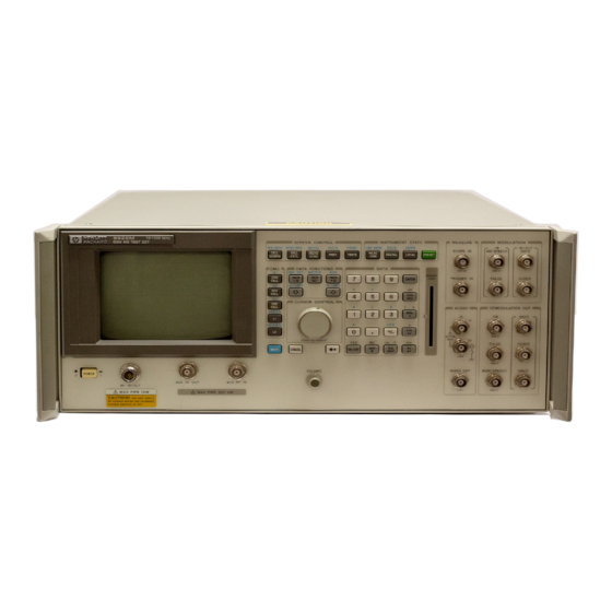
Connectors Front-Panel Connectors of the Agilent Technologies 8922M/S Front-Panel Connectors of the Agilent Technologies 8922M/S 1. AUX RF IN The auxiliary RF input connects to the input section and to the RF analyzer (if selected). This connector provides a higher sensitivity and lower maximum-power connection from the DUT. - Page 251 Connectors Front-Panel Connectors of the Agilent Technologies 8922M/S 3. CLOCK The clock connector is connected to the power ramp’s digital demodulation clock (DEMODULATION output. This signal is the digital demodulation CLOCK signal which is generated OUT) when digitally demodulating one out of eight timeslots of GSM 0.3 GMSK (Agilent 8922M modulation.
- Page 252 Cond or Uncond from the Cell Control 2 screen, Speech field. (Agilent 8922M This connector is also used as the DC AM input of the Agilent 8922M/S. To select Only) DC AM, choose Ext from the RF Generator/RF Analyzer screen, DC AM field. The RF carrier will now be AM modulated (with fixed sensitivity) through this...
- Page 253 Connectors Front-Panel Connectors of the Agilent Technologies 8922M/S 8. IN HI (AUDIO) The input high connector is connected to the audio analyzer input. This connector is used as the main (external) audio analyzer input connection (when selected). This connector is also used in combination with the audio input low signal to input a floating input signal (for better noise performance) to the audio analyzer.
- Page 254 Connectors Front-Panel Connectors of the Agilent Technologies 8922M/S 10. IN/OUT DATA Data Input This connector is a data input when the instrument is settable. (MODULATION) (See the Cell Configuration screen.) It is used to input 0.3 (Agilent 8922M GMSK modulation data (if selected) to the RF generator.
- Page 255 Connectors Front-Panel Connectors of the Agilent Technologies 8922M/S 12. MON/SPEECH This connector is the output of the audio analyzer. One of several uses for this (Agilent 8922M connector is to monitor the received speech from an MS. To choose demodulated Only) speech, select SpeechOut from the Audio screen, AF Anl In field.
- Page 256 WARNING: If you have the Agilent 8922M/S Option 010 Multi-Band Test System, do not connect the mobile to this port. This is connector is selected when the RF generator’s RF output is set to RF IN/ OUT or when the RF analyzer’s RF input is set to RF IN/OUT.
- Page 257 Connectors Front-Panel Connectors of the Agilent Technologies 8922M/S 18. TRIGGER IN The measurement trigger input is the trigger source for the oscilloscope, spectrum (MEASURE) analyzer (option 006), Pwr Ramp, Phase/Freq and Data demodulation. All triggered measurements, when trigger is selected as external, are triggered by this signal.
-
Page 258: Rear-Panel Connectors Of The Agilent Technologies 8922M/S
Connectors Rear-Panel Connectors of the Agilent Technologies 8922M/S Rear-Panel Connectors of the Agilent Technologies 8922M/S 1. 10 MHz OUT The 10 MHz output connector is connected to the 10 MHz oscillator in the reference circuitry. This signal is a general-purpose 10 MHz reference output (sine wave). - Page 259 Connectors Rear-Panel Connectors of the Agilent Technologies 8922M/S 3. AM This connector is used in conjunction with the HP/Agilent 83220A and HP/Agilent 83220E DCS/PCS Test Sets. Refer to either the HP/Agilent 83220A or HP/Agilent 83220E User’s Guides for further information.
- Page 260 Connectors Rear-Panel Connectors of the Agilent Technologies 8922M/S Electrical Characteristics of the DAI/EMMI The state of a signal pin is defined by the voltage (V) between the pin and its associated ground. Logical State Voltage (V) Current 0 or LOW or ON 0 V <...
- Page 261 Connectors Rear-Panel Connectors of the Agilent Technologies 8922M/S General Purpose Agilent Agilent Agilent General Purpose General Purpose 6-13...
- Page 262 The option 001 reference output connector, when present, is connected to an high- stability 10 MHz reference. Typically, it is connected to REF IN (using an Agilent supplied short jumper cable) to get all timebase references locked to the high- stability timebase reference.
- Page 263 25 Signal Ground (nAutoFd, nSelectIn and nInit) 8. PCN Interface This connector is used in conjunction with the HP/Agilent 83220A and HP/Agilent 83220E DCS/PCS Test Sets. Refer to either the HP/Agilent 83220A or HP/Agilent 83220E User’s Guides for further information.
- Page 264 This connector is the main timebase reference input. Normally, it is connected to Option 001 REF OUT (if option 001 is installed) using an Agilent- supplied short jumper cable. RF IN can also be connected to a user-provided 1, 2, 5, 10 or 13 MHz reference by selecting the appropriate frequency from the Reference field on the Configure screen.
- Page 265 See Also Signal Descriptions for the System Bus NOTE This feature is not supported in the Agilent 8922S. 14. VIDEO OUT The video output connector connects to the CRT hardware. It can be used to connect a larger display.
-
Page 266: Signal Descriptions For System Bus
Connectors Signal Descriptions for SYSTEM BUS Signal Descriptions for SYSTEM BUS System Bus Pin Number Overview Table 2-1 System Bus Connector Pin Numbers Signal Name Signal Name Number Number FP_DATA FP_CLOCK MEAS_TRIG_OUT RP_GSM_RST_IN DEMOD_DATA DEMOD_CLK DEMOD_VALID RP_GSM_RST_OUT G_EXT_TRIG_OUT PULSE_MOD_IN RP_DMOD_TRIG RP_BURST_T1 RP_BURST_T2 RP_BURST_T3... - Page 267 Connectors Signal Descriptions for SYSTEM BUS DEMOD_DATA, DATA-Pin 22 CLK-Pin 4 VALID-Pin 23 Outputs DEMOD_CLK, These are the digital demodulation data output signal, the digital demodulation DEMOD_VALID clock output signal, and the digital demodulation valid output signal. These signals are connected directly in parallel with their respective front-panel connectors. See Also Front Panel Connectors: DATA (DEMODULATION OUT), CLOCK (DEMODULATION OUT), VALID...
- Page 268 Connectors Signal Descriptions for SYSTEM BUS PULSE_MOD_IN Pin 6 Input This is the pulse modulation input. This signal is connected directly in parallel with the PULSE (MODULATION IN) front-panel connector. NOTE The two inputs are directly coupled to each other. Avoid putting signals on both inputs simultaneously.
- Page 269 RP_GSM_RST_IN Pin 3 Input This connector is an active low input that halts and resets the Agilent 8922 GSM counters (frame, timeslot, and bits). It is used when two or more Agilent 8922M/S are connected together (daisy-chained) to simulate a GSM system.
- Page 270 Connectors Signal Descriptions for SYSTEM BUS RP_HOP_ADRS0, ADRS0-Pin 12, ADRS1-Pin 31 ADRS2-Pin 13, ADRS3-Pin 32 ADRS4-Pin 14, through ADRS5-Pin 33 ADRS6-Pin 15, ADRS7-Pin 34 ADRS8-Pin 16, ADRS9-Pin 35 RP_HOP_ADRS9, ADRS10-Pin 17, Inputs RP_HOP_ADRS10 These are the rear-panel hop frequency table address input lines. They connect to the to hop controller.
- Page 271 Connectors Signal Descriptions for SYSTEM BUS RP_HOP_INHIBIT Pin 30 Input This is the rear-panel internal hop inhibit input. It connects to the hop controller. It is used to inhibit internal hopping. The internal hop sequence address register is still sequenced, however. This signal should normally be kept TTL high. This line is active whenever the hop controller’...
- Page 272 Connectors Signal Descriptions for SYSTEM BUS RP_RX_HOP Pin 10 Input This is the rear-panel trigger signal input for hopping the RF analyzer (if selected). It is used when externally addressing the hop frequencies. You must supply signals on the rear-panel hop frequency table address input lines to select each RF analyzer hop frequency for each RF analyzer hop trigger.
- Page 273 Connectors Signal Descriptions for SYSTEM BUS RP_TXD, RP_RXD TXD-Pin 37 RXD-Pin 18 Output/Input These are the rear-panel serial transmit data and rear-panel serial receive data lines. NOTE Ground signals not listed individually here. RP_TX_HOP Pin 28 Input This is the rear-panel trigger signal input for hopping the RF generator (if selected). It is used when externally addressing the hop frequencies.
- Page 274 Connectors Signal Descriptions for SYSTEM BUS USE_MEM_EXT_T 27 Pin Input This is the external trigger source for Use Mem. When Trig Source is Ext (see Screens: Digital Demod), a TTL high on this pin will initiate data capture for Use Mem. RP_BURST_T1 and RP_BURST_T2 must select the correct burst number (see signal descriptions for RP_BURST_T1, RP_BURST_T2).
-
Page 275: Timing Diagrams
Connectors Timing Diagrams Timing Diagrams Figure 6-2 Digital Demodulation Timing Specification Table 6-27... - Page 276 Connectors Timing Diagrams Figure 6-3 Digital Demod Timing Diagram 6-28...
- Page 277 Connectors Timing Diagrams Figure 6-4 Frequency Hop Timing Specification Table 6-29...
- Page 278 Connectors Timing Diagrams Figure 6-5 RF Generator Hop (Address Source = Ext) Timing Diagram 6-30...
- Page 279 Connectors Timing Diagrams Figure 6-6 RF Analyzer Hop (Address Source = Ext) Timing Diagram 6-31...
- Page 280 Connectors Timing Diagrams Figure 6-7 RF Generator Hop (Address Source = Int) Timing Diagram 6-32...
- Page 281 Connectors Timing Diagrams Figure 6-8 RF Analyzer Hop (Address = Int) Timing Diagram 6-33...
- Page 282 Connectors Timing Diagrams Figure 6-9 Reset Hop Once (Address Source = Int) Timing Diagram 6-34...
- Page 283 Connectors Timing Diagrams Figure 6-10 Reset and Hold Hop (Address Source = Int) Timing Diagram 6-35...
- Page 284 Connectors Timing Diagrams Figure 6-11 Hop Inhibit (Address Source = Int) Timing Diagram 6-36...
-
Page 285: Messages
MEAS SYNC SHIFT Messages can be reviewed by pressing , (MSSG). If you have the Agilent 8922M/S Option 010 Multi-Band Test System, there may be additional error messages. Refer to the appropriate Agilent 8922 Multi-Band User’s Guide for more information. -
Page 286: Communication Failures
Messages Communication Failures Communication Failures The following four messages require you to cycle power on the instrument to continue any operation. • DSP Analyzer Communication Failure • Hop Controller Communication Channel Failure • Protocol Processor Communication Channel Failure • Communication failure with Signaling Board... -
Page 287: Firmware Error
Firmware Error Firmware Error During a power-up cycle the following error message may appear; Firmware revision error in module XXXXX Take a note of the module name and contact your local Agilent Technologies Sales and Service Office for more information. -
Page 288: Sync Status
Messages Sync Status Sync Status This field displays any errors that occurred while trying to synchronize the demodulated data. Some screens use this field to display progress during multi-burst measurement. When the measurement is completed to field returns to its normal state. -
Page 289: Protocol Error Messages
Errors are fatal for calls in progress or signalling being attempted. Timer names are taken from GSM Rec. 04.06, 04.08 and 05.08, with the exception of T3299, which is Agilent unique. The timer expiry appears at the top of the display and is of the form: ”Call disconnected: timer T??? expired.”... -
Page 290: Timers
T3250 TMSI_REAL_CMD or LOC_UPD_ACC timer Management ”MS failed to acknowledge a new TMSI.” Timers. T3260 AUTHENT_REQUEST timer ”MS failed to authenticate.” T3270 IDENTITY_REQUEST timer ”MS failed to identify.” T3299 HP Unique timer: CIPHER_REQUEST ”HP 8922M/S failed to configure for ciphering.”... - Page 291 Messages Timers Call Control Timers. T301 Call Received timer ”MS failed to connect.” T303 Call Present timer ”MS failed to respond to SETUP with CALL_CONF or REL_COMP.” T305 Disconnect Indication timer ”MS failed to respond to DISC with REL or DISC.” T306 Disconnect Indication Tone timer ”MS failed to respond to DISC with REL or DISC.”...
-
Page 292: Disconnects
I/O overloaded. 0x00ab T100 expired. 0x00ac Protocol Message Allocation failed. Data Link Layer Data Link layer error codes are proprietary to the Agilent 8922M/S. The defined Disconnects error codes are as follows: ”Call disconnected: DL Error: 0x00??” Causes: 0x00c8 SAPI incorrect. - Page 293 MS rejected. Call Control Layer Call Control sub-layer error codes are actually CC cause values as defined by Rec. Disconnects 04.08 Table 10.53. The cause values used by the Agilent 8922M/S are as follows: ”Call disconnected: CC Cause: 0x00??” Causes: 0x0001 Unassigned number.
- Page 294 Messages Disconnects 0x0051 Invalid call reference value. 0x0058 Incompatible destination. 0x005f Invalid message, unspecified. 0x0060 Mandatory information element error. 0x0061 Message type non-existent or not implemented. 0x0062 Message not compatible with call state or message type non-existent or not implemented. 0x0063 Information element non-existent or not implemented.
-
Page 295: Protocol Log Examples Of Typical Calls
The sample protocol log of the Common Air Interface was obtained using the LOGGING Pass_Filter set to: ‘+Service’. The system parameters used were the Agilent 8922M/S power on defaults except for changing TCH2 to use MA2. Only OSI Control Stack traffic is shown. Management stack traffic configuring the Agilent 8922M/S is not shown. -
Page 296: Monitoring For Protocol Failure And Recovery During Test
When the error: ‘Call disconnected: PH Error: 0x009d’ (or 0x009f) is encountered, a fatal protocol error has been detected by the Agilent 8922M/S and it has reconfigured back to the BCCH. Testing may resume from a point at which the mobile is camped. -
Page 297: Instrument Basic
Instrument BASIC... -
Page 298: Agilent Technologies 8922M/S Instrument Basic Overview
Agilent Technologies 8922M/S Instrument BASIC Overview The Agilent 8922M/S contains an HP Instrument BASIC computer that can run programs to control the Agilent 8922M/S and any connected GPIB equipped instruments. This provides a powerful test instrument and test system controller in one package. - Page 299 Instrument BASIC Agilent Technologies 8922M/S Instrument BASIC Overview Programs That Use the TESTS Subsystem The TESTS subsystem’s capabilities were designed to allow the operator to “pick and choose” the tests and parameters they need from a larger set, eliminating unnecessary tests and reducing test time. This is especially helpful when a very large program has been written containing several tests and a multitude of associated specifications, test parameters and frequencies.
-
Page 300: Configuration And Instrument Control
Multiple Controllers Only one system controller can be connected to the bus at any time. If the Agilent 8922M/S is used in a test system that has its own controller, the Agilent 8922M/S can not be used as a controller unless the system controller is turned off or disconnected from the bus. - Page 301 Instrument BASIC Configuration and Instrument Control Hardware Agilent 8922M/S provides an RS-232 Serial port and an GPIB port for a variety of Connections and uses: Agilent 8922M/S • Controlling the Agilent 8922M/S using a connected controller Configuration • Controlling connected instruments using the Agilent 8922M/S IBASIC computer •...
- Page 302 RJ-11 Connectors RJ-11 cables and adapters can be wired differently. If you buy a cable or adapter from a supplier other than Agilent, verify the connections for the pins indicated in the following table before connecting cables to the instruments.
- Page 303 Configuring the 1 Access the Agilent 8922M/S’s I/O CONFIGURE screen. Agilent 8922M/S 2 Set Serial In field to Inst to allow the Agilent 8922M/S’s IBASIC controller to accept characters from a PC or ASCII terminal. 3 Set IBASIC Echo to On.
- Page 304 Instrument BASIC Configuration and Instrument Control 1 Load and run HP AdvanceLink on your PC. 2 Set the Global Configuration settings. Keyboard: USASCII Personality: HP Language: ENGLISH Terminal Mode: Alphanumeric Remote To: (Enter your PC’s serial port number.) Printer I/F: None Memory Size: 32K Plotter I/F: None HP Mode: Yes...
- Page 305 8 HELLO WORLD should be displayed on the Agilent 8922M/S and the terminal/PC’s screen. After the cable and adapter have been connected, and the Agilent 8922M/S and terminal (or PC) have been configured, you should be able to type on your terminal’s keyboard and “talk”...
-
Page 306: Loading, Storing, And Running
LOAD “<filename>:7xx,x” Downloading An This procedure downloads an IBASIC program from your connected IBASIC IBASIC Program computer to the Agilent 8922M/S’s IBASIC Controller. This procedure assumes Into the your Agilent 8922M/S’s GPIB address is set to 14. Agilent 8922M/S 1 Access the Agilent 8922M/S’s IBASIC Controller screen. - Page 307 Instrument BASIC Loading, Storing, and Running Storing IBASIC 1 Use the previous procedure to download your program into the Agilent Programs On 8922M/S’s RAM. Memory Cards 2 Press LOCAL SHIFT CANCEL on the Agilent 8922M/S to perform an IBASIC reset.
- Page 308 Instrument BASIC Loading, Storing, and Running Figure 8-2 Loading a Test Procedure 3 Select the Procedure field. Refer to item (3), see Figure 8-3 on page 8-13. 4 Choose the Test Procedure file that you want to download. Refer to item (4), see Figure 8-3 on page 8-13.
- Page 309 Instrument BASIC Loading, Storing, and Running NOTE The Test Procedure file should have a Test Library file with the same name. Refer to the Programming and Using the TEST Subsystem for descriptions of Test Procedure and Library files, and how these files relate to the program’s code file. Figure 8-3 Loading a Test Procedure Making or Deleting...
- Page 310 Instrument BASIC Loading, Storing, and Running Figure 8-4 Test Procedure and Test Library Files 3 Select the Procedure field shown by item (3), see Figure 8-5 on page 8-15. 4 Enter the Test Procedure filename that you want to make or delete by using the alpha/numeric list of characters shown by item (4), see Figure 8-5 on page 8-15.
- Page 311 If at any time you need to stop testing, press the front-panel CANCEL key. NOTE A program takes up to 3 minutes to load into the Agilent 8922M/S and is loaded when the Run Test field is first pressed. SHIFT CANCEL...
-
Page 312: Entering And Editing Programs
The IBASIC Controller screen is the “computer” for the TESTS subsystem. You enter and edit programs just like any other IBASIC computer, with the exceptions that the Agilent 8922M/S does not have a computer keyboard connected directly to it, and full screen editing does not yet exist. - Page 313 Agilent 8922M/S. The usual development sequence is: 1 Write the program on your computer to control the Agilent 8922M/S using the normal 7xx GPIB address. 2 Run the program to verify that it controls the Agilent 8922M/S correctly.
- Page 314 2 Access the IBASIC Controller screen. Downloading A Program Into the Agilent 8922M/S This procedure assumes your Agilent 8922M/S’s GPIB address is 14. If it is not, change the address in the following procedure to match your instrument’s address. 1 Load the IBASIC program to be downloaded into your controller.
- Page 315 Instrument BASIC Entering and Editing Programs Line-by-line Entry and Editing Program lines in the Agilent 8922M/S’s RAM can be entered and edited one line at a time from your computer using the PROG command - OUTPUT Addr;”PROG:EXEC ‘<program line/command> ’”...
-
Page 316: Memory Cards
Figure 8-7 on page 8-21 illustrates how to insert a memory card into the Agilent Cards 8922M/S front panel. To remove a memory card, simply pull it out. Pay attention to memory-card orientation as it’s inserted; otherwise, the card will not be seated correctly in the slot. - Page 317 Instrument BASIC Memory Cards Figure 8-7 Inserting a Memory Card Types of Memory Cards Two types of memory cards may be purchased from Agilent Technologies as shown in Table 1 on page 8-21: • SRAM (Static Random-Access Memory), or •...
- Page 318 Instrument BASIC Memory Cards Initializing an SRAM Memory Card An SRAM memory card must be initialized before it can be used. Initialize the SRAM memory card by using the COPY_PL program (which at the same time you can copy Test Procedure and Test Library files to the memory card). Otherwise, initialize the SRAM card using the IBASIC computer as follows: TESTS 1 Press the front-panel...
- Page 319 Backing Up the Memory-Card Programs SRAM memory cards contain a battery to preserve its contents when the Agilent 8922M/S is turned off or when the card is removed. Memory-card contents may be backed up using the following procedure: Procedure for Backing Up a Memory Card The program COPY_PL on Agilent 8922M/S ROM backs up Test Procedure and Test Library files onto a SRAM memory card.
- Page 320 Instrument BASIC Memory Cards NOTE Test Procedure files are identified in the IBASIC screen when a catalog (CAT) is done. A lowercase “p” is prefixed to a Test Procedure filename. Test Library filenames are prefixed with a lowercase “l.” 1 Press the front-panel key.
- Page 321 Write the date a battery is installed in the memory card. The date is important for determining when to replace the battery. When the battery needs replacing, insert the card into the Agilent 8922M/S and turn the POWER switch on. An inserted memory card takes power from the Agilent 8922M/S preventing the card’s contents from being lost.
-
Page 322: Programming And Using The Tests Subsystem
IBASIC Code file that can reside either on the Memory card, on an external disk drive connected to the GPIB port of the Agilent 8922M/S, or in an internal RAM disk. The name of this file is preceded by a lower case ‘c’. This tells the TESTS subsystem that this particular file contains program code. - Page 323 Instrument BASIC Programming and Using the TESTS Subsystem Figure 8-10 TESTS Subsystem File Relationship TESTS Subsystem The TESTS subsystem uses several screens to create, select, and copy files, and to Screens run tests. The Main TESTS Subsystem Screen Refer to Figure 8-11 on page 8-28. The Main TESTS screen is accessed by pressing the front panel key.
- Page 324 Instrument BASIC Programming and Using the TESTS Subsystem Figure 8-11 The Main TESTS Subsystem Screen TESTS Subsystem The TESTS subsystem allows the user to easily modify the test subroutines, User-Interface parameters, specifications and configuration to correspond to the requirements of a Screens specific Radio.
- Page 325 Three alpha characters are also displayed in the upper-right corner of the screen to indicate status: • An “R” indicates the Agilent 8922M/S is in remote operation; the absence of an “R” means the Agilent 8922M/S has changed to local operation. •...
- Page 326 Run Mode.….……Continuous All tests run in sequence. Testing pauses only if the operator is required to interact with the UUT or Agilent 8922M/S; interaction such as changing UUT channels, setting squelch, changing audio level, and so forth, cause testing to pause.
- Page 327 Refer to item (4) in Figure 8-12 on page 8-30. Output Destination.….……Crt Test results are output to the Agilent 8922M/S CRT screen only. Output Destination.….……Printer Test results are output to the CRT and printer. A printer must be correctly configured in order to get a printout.
- Page 328 Ensure the Autostart field toggle is set to On (see Figure 8-13 on page 8-32 (1)); this allows the Agilent 8922M/S to go straight to the Procedure Menu each time the Agilent 8922M/S is switched on, providing a Memory Card is inserted in the front panel of the Agilent 8922M/S.
- Page 329 Instrument BASIC Programming and Using the TESTS Subsystem 5 Select the Yes/No field and decide if the test is to be run on all channels (select Yes), or if the test is to be run on prime channels only (select No). (Prime channels are selected from the Edit Freq field.) Four factors determine how long it takes to test a radio: •...
- Page 330 3 Select a new Test name for the inserted step. 4 Press or select Delet Stp to remove steps from a procedure. Figure 8-15 Edit Sequence Screen on the HP/Agilent 83212X NOTE The tests you select determine the specifications that are required. Editing Test Parameters...
- Page 331 NOTE For a fuller explanation of the fields see Edit Parameter. Figure 8-16 Edit Parameters Screen on the HP/Agilent 83212X Select the following information according to the labelled steps in Figure 8-16 on page 8-35: 1 Select the parameter to modify, either by scrolling with the knob or entering the Parameter Number with the Data Keypad.
- Page 332 Instrument BASIC Programming and Using the TESTS Subsystem 1 Select the front-panel key, and then the Test Function Edit Cnfg. TESTS A configuration screen similar to that shown in Figure 8-17 on page 8-37 appears. 2 Select the Calling Name field and enter the instrument’s name in upper-case letters.
- Page 333 Instrument BASIC Programming and Using the TESTS Subsystem Figure 8-17 Instrument-Configuration Screen Program Structure for TESTS Subsystem Programs Writing programs that take advantage of the TESTS subsystem capabilities requires the programmer to understand how to structure the program to access the TESTS subsystem user-interface screens.
- Page 334 ! THE FIRST LINE MUST CONTAIN THE NAME OF THE LIBRARY !__________________________________________________________ ! THIS PROGRAM IS A DEMO PROGRAM TO DEMONSTRATE THE USE ! OF THE TEST SUBSYSTEM ON THE Agilent 8922M ! REVISION: 1 APRIL, 1991 !___________________________________________________________ COM /I_o/ I_o$[470]...
- Page 335 Instrument BASIC Programming and Using the TESTS Subsystem IF T_it$=”Y” THEN PRINT TABXY(2,6),”RX FREQUENCY = “,Rx_f PRINT TABXY(2,7),”TX FREQUENCY = “,Tx_f PRINT TABXY(2,8),”TEST THIS FREQUENCY ?”,T_it$ Run_ts=1 RUN THROUGH THE SEQUENCE OF TESTS REPEAT Done_t=0 ENTER IN THE TEST SEQUENCE OUTPUT 800;”TESTS:SEQN? “&VAL$(Run_ts) I_o$=””...
- Page 336 Instrument BASIC Programming and Using the TESTS Subsystem 1110 Calling_name$=I_o$[4;21] 1120 Model$=I_o$[27;21] 1130 I1addr=VAL(TRIM$(I_o$[50])) 1140 Options$=I_o$[54] 1150 GET SPECIFICATION 1 FOR THIS TEST 1160 OUTPUT 800;”TESTS:SPEC? “&VAL$(1) 1170 I_o$=”” 1180 ENTER 800;I_o$ 1190 IF I_o$[1;5]=”Error” THEN 1200 PRINT TABXY(2,14),”ERROR IN RECALLING THE SPECIFICATIONS FOR TEST 1”...
- Page 337 310: Ch keeps track of which channel we are currently testing. 320: Now Repeat for all Frequencies: 330: Request all the channel values from the Agilent 8922M/S. 340: I_o$ gets the string return. 370: The Rx frequency is pulled from the string.
- Page 338 Instrument BASIC Programming and Using the TESTS Subsystem 590: Initialize I_o$ to a null string. 600: I_o$ holds the value of the return string. 610: Tst now hold the value of the current test. This value is equal to the index of the Test Name in the Test selection list shown on the Test Seqn screen.
- Page 339 Instrument BASIC Programming and Using the TESTS Subsystem 880: Indicate that one of the tests have failed. 890: The goto for the end of the program. 900: End of the main program. 910: Subroutine T01-This corresponds with test #1. This subroutine illustrates how to enter values from the Parameters, Configuration, and Specification screens.
- Page 340 Instrument BASIC Programming and Using the TESTS Subsystem 1230: Set the lower limit from the value in the string. 1240: Set the upper limit from the value in the string. 1250: Set Test$ to whether “Upper”, “Lower”, “Both”, or “None” of the specs are to be tested.
- Page 341 APPENDIX A...
-
Page 342: Purpose
This feature is not available on the Agilent 8922S. Protocol Logging captures protocol messages to and from the mobile station in buffers in the Agilent 8922M. Messages can then be sent to an external Protocol Logger, such as the HP/Agilent 37900D, through the Protocol Interface connector on the rear panel. -
Page 343: Equipment Required
HP/Agilent 37967A HP/Agilent 8922G protocol monitor application software. HP/Agilent 37966B GSM software. HP/Agilent 15756A Interface Cable. HP/Agilent 37910A Slave Signalling Card. HP/Agilent 37913A RS232/449 Datacomms Interface Card. Agilent 8922M Option 003. All software should be loaded into the HP/Agilent 37900D. -
Page 344: Connecting The Agilent 8922M To The Hp/Agilent 37900D
HP/Agilent 37900D Option 004 Rear Panel Figure A-2 Cabling Setup - Rear View Using HP/Agilent 15756A Interface cable, connect PORT A on the rear of the HP/Agilent 37900D to the Protocol Interface Port on the rear panel of the Agilent 8922M. -
Page 345: Setting Up The Agilent Technologies 8922M
Setting Up the Agilent Technologies 8922M Camp On Firstly, the Mobile Station should be "camped" on to the Agilent 8922M. That is the MCC, MNC, LAC should all be correct, and any adjustments to power level made as appropriate to the Mobile under test. -
Page 346: Setting Up The Hp/Agilent 37900D
MANUAL MODE HELP NOTE It is acceptable to select 8922G from the HP/Agilent 37900D. This option is a drop- in replacement for 8922M. Set Up Interface Ensure that the HP/Agilent 37913A Interface Card is set up correctly. Refer to the list Card below for Port A setting requirements;... - Page 347 Select Quit (’Q’ from keyboard) twice. Select Yes (’Y’ from keyboard) to return to start-up screen. Refer to the HP/Agilent 37900D Monitor Guide for detailed information on using the HP/Agilent 37900D Signaling Test Set.
-
Page 348: How To Obtain A Protocol Log
Press 1 to get a more detailed look at link 1 on the MONITOR ISDN SIGNALLING LINK 1 screen. This is the link to which the cable from the Agilent 8922M is attached. If the link is good, then the Signalling Bit Rate under Channel 1 should be shown as 64000 Hz. - Page 349 As the call comes up, there will be assignment appearing on the display of the HP/Agilent 37900D. Real Time To see the messages themselves on the HP/Agilent 37900D, press ’R’ to get a real Message Display time display of incoming messages. These are short summaries of each message. To return to the MONITOR ISDN SIGNALLING LINK1 screen, select ’1’...
- Page 350 To end the call, on the Mobile Station handset, press ’END’. At this point the call will drop. There may not have been enough messages on the Agilent 8922M to fill the cache for the last messages to be put out to the HP/Agilent 37900D.
-
Page 351: Additional Information
The logging screen gives you control over the Protocol Interface port on the rear panel (option 003). This function is selected by highlighting More and selecting LOGGING. No protocol logging messages appear on the Agilent 8922M Logging screen. 1. Clear Log Clear erases the contents of the logging buffers. - Page 352 GSM recommendations. It does not include HP proprietary messages. Remote Control of It is possible to control the logging functions of the Agilent 8922M over the GPIB Protocol Logging interface. For more details on how to do this refer to the Agilent 8922M/S GSM Test Set Programming Reference Guide.
-
Page 353: Protocol Log Of A Typical Call
This is a protocol log of the Common Air Interface (CAI) for a typical call placed between the Agilent 8922M/S and a GSM Mobile Station. You are expected to be familiar with ETSI standards GSM 04.06 and 04.08 to understand these protocol logs. - Page 354 RR->DL DL_UNIT_DATA AGCH RR Immediate Assignment 06 3f 03 20 a0 14 92 aa 2e 00 00 Frame 2446653 DL->PH PH_DATA AGCH L2 ABIS M0 RR Immediate Assignment Frame 2446653 Agilent 8922M/S PH->DL PH_CONNECT SDCCH Frame 2446654 configures to DCH PH->DL PH_CONNECT SACCH Frame 2446654 PH->DL READY_TO_SEND SDCCH Frame 2446694...
- Page 355 APPENDIX A Protocol Log of a Typical Call port Frame 2446738 DL->RR DL_UNIT_DATA SACCH RR Measurement Report 06 15 37 77 00 00 00 00 00 00 00 00 00 00 00 00 00 00 Frame 2446738 PH->DL READY_TO_SEND SDCCH Frame 2446745 DL->PH PH_DATA SDCCH UA F1 CR0 SAPI0 M0 RR Paging Response Frame 2446745 PH->DL PH_DATA SDCCH UI P0 CR0 SAPI0 M0 Frame 2446769...
- Page 356 RR->DL DL_RELEASE SDCCH Frame 2446906 DL->RR DL_RELEASE SDCCH Frame 2446906 RR->DL DL_RELEASE SACCH Frame 2446906 DL->RR DL_RELEASE SACCH Frame 2446906 Agilent 8922M/S PH->DL PH_CONNECT FACCH_F Frame 2446911 Configures to TCH PH->DL PH_CONNECT SACCH_TF Frame 2446911 PH->DL PH_DATA FACCH_F SABM P1 CR0 SAPI0 M0 Frame 2446923 DL->DL READY_TO_SEND FACCH_F Frame 2446923...
- Page 357 APPENDIX A Protocol Log of a Typical Call PH->DL PH_DATA FACCH_F I Nr0 Ns1 P0 CR0 SAPI0 M0 CC Alerting Frame 2446988 DL->DL READY_TO_SEND FACCH_F Frame 2446988 DL->RR DL_DATA FACCH_F CC Alerting 83 41 Frame 2446988 DL->PH PH_DATA FACCH_F RR Nr2 PF0 CR0 SAPI0 M0 Frame 2446988 RR->MM RR_DATA CC Alerting 83 41 Frame 2446989 MM->CC MM_DATA CC Alerting 83 41 Frame 2446989 CC->HST CC_ALERT Frame 2446989...
- Page 358 00 78 01 a0 00 00 00 00 00 00 00 00 00 00 Frame 2447682 RR->DL DL_RELEASE FACCH_F Frame 2447685 DL->RR DL_RELEASE FACCH_F Frame 2447685 RR->DL DL_RELEASE SACCH_TF Frame 2447685 DL->RR DL_RELEASE SACCH_TF Frame 2447686 Agilent 8922M/S PH->DL PH_CONNECT FACCH_F Frame 2447699 GOES TO NEW PH->DL PH_CONNECT SACCH_TF Frame 2447699 TCH2 PH->DL PH_DATA FACCH_F SABM P1 CR0 SAPI0 M0 Frame 2447716...
- Page 359 APPENDIX A Protocol Log of a Typical Call DL->DL READY_TO_SEND FACCH_F Frame 2447716 DL->RR DL_ESTABLISH FACCH_F Frame 2447717 DL->PH PH_DATA FACCH_F UA F1 CR0 SAPI0 M0 Frame 2447717 PH->DL READY_TO_SEND FACCH_F Frame 2447724 PH->DL READY_TO_SEND SACCH Frame 2447728 DL->PH PH_DATA SACCH_TF UI P0 CR1 SAPI0 M0 RR System Information Type 6 Frame 2447728 PH->DL PH_DATA FACCH_F I Nr0 Ns0 P0 CR0 SAPI0 M0 RR Assign- ment Complete Frame 2447751...
- Page 360 RR->DL DL_RELEASE FACCH_F Frame 2448978 DL->RR DL_RELEASE FACCH_F Frame 2448978 RR->DL DL_RELEASE SACCH_TF Frame 2448978 DL->RR DL_RELEASE SACCH_TF Frame 2448978 Agilent 8922M/S PH->DL PH_CONNECT FACCH_F Frame 2448982 configures to new PH->DL PH_CONNECT SACCH_TF Frame 2448982 PH->DL MPH_ACCESS RACH Frame 2448987 DL->RR MDL_ACCESS RACH Frame 2448988...
- Page 361 APPENDIX A Protocol Log of a Typical Call Frame 2449020 DL->DL READY_TO_SEND FACCH_F Frame 2449020 DL->PH PH_DATA FACCH_F UI P0 CR1 SAPI0 M0 RR Physical Information Frame 2449020 PH->DL READY_TO_SEND FACCH_F Frame 2449023 RR->DL DL_UNIT_DATA FACCH_F RR Physical Information 06 2d 00 Frame 2449030 DL->DL READY_TO_SEND FACCH_F Frame 2449031 DL->PH PH_DATA FACCH_F UI P0 CR1 SAPI0 M0 RR Physical Information...
- Page 362 APPENDIX A Protocol Log of a Typical Call Inter-cell handover complete Call termination HST->CC CC_DISC Frame 2449729 CC->MM MM_DATA CC Disconnect 03 25 02 e0 90 Frame 2449729 MM->RR RR_DATA CC Disconnect 03 25 02 e0 90 Frame 2449729 RR->DL DL_DATA FACCH_F CC Disconnect 03 25 02 e0 90 Frame 2449729 DL->DL READY_TO_SEND FACCH_F Frame 2449729 DL->PH PH_DATA FACCH_F I Nr1 Ns0 P0 CR1 SAPI0 M0 CC Disconnect Frame 2449729...
- Page 363 PH->DL PH_DATA FACCH_F DISC P1 CR0 SAPI0 M0 Frame 2449909 DL->DL READY_TO_SEND FACCH_F Frame 2449909 DL->PH PH_DATA FACCH_F UA F1 CR0 SAPI0 M0 Frame 2449909 PH->DL READY_TO_SEND FACCH_F Frame 2449916 DL->RR DL_RELEASE FACCH_F Frame 2449930 Call termination complete, HP 8922M/S configures to BCCH A-23...
- Page 364 APPENDIX A Protocol Log of a Typical Call A-24...
- Page 365 Glossary...
- Page 366 Glossary ARFCN Absolute Radio Frequency Channel Number The BCH (Broadcast Channel) is a beacon which is always turned on so that mobile can look out for it when trying to find service. A useful BCH always carries information in timeslot 0. The BCH ARFCN has to be active in all timeslots to allow mobiles to synchronize to other cells.
- Page 367 Glossary Burst-by-Burst Bit Error Rate The Burst-by-Burst Bit Error Measurement makes use of a new loopback path within the mobile to calculate the equivalent Class II BER. This measurement is 5 times faster than the conventional method. This is also sometimes known as Fast Bit Error Measurement.
- Page 368 Glossary only uses one burst in 26. When the FACCH steals control from the TCH small drop-outs in the speech can often be heard. Frame A repetitive collection of time slots in a TDMA system. GMSK Gaussian Filtered Minimum Shift Keying. The type of digital modulation used for the GSM system.
- Page 369 Glossary RPE-LTP Regular Pulse Excitation Long Term Prediction. A commonly used technique for converting voice from analog to digital form. This is the CODEC that is used by GSM, DCS1800 and PCS1900 systems. RSSI Received Signal Strength Indicator. Reception level. SACCH There is a spare frame every 12 TCH frames and this is used for the SACCH (Slow Associated Control Channel).
- Page 370 Glossary...
-
Page 371: Index
Aux BCCH Pulse, 4-104 Cell Configuration, 4-18, 4-24 ABORTS, A-8 Pulse Fall, 4-109 Aux RF In from the Agilent 8922M, A-8 Pulse Rise, 4-107 Configure, 4-49 sending to HP/Agilent 37900D, A-8 Pwr Ramp (Fall Edge), 4-99 Aux RF Out absolute radio frequency channel... - Page 372 Cell Control, 4-39 Bit Error Test, 4-10 LAC, A-5 Connection, A-2, A-4 RF Analyzer, 4-113 MCC, A-5 Agilent 8922M to HP/Agilent 37900D, Control Ch MNC, A-5 Cell Config, 4-19, 4-25 More information, A-5 bar graphs, A-9 control channel, 4-19, 4-25...
- Page 373 Index trols), 4-127 disk address, 4-59 Pulse, 4-104 Spectrum Analyzer (Main Controls), 4- Display Logging Screen Fast Bit Error HP/Agilent 37900D, A-8 Round Trip Delay, 4-58 Spectrum Analyzer (Marker Controls), Display Messages, A-9 ff at end 4-125 Do Open Cal...
- Page 374 HP/Agilent 37966A GSM software, A-3 Bit Error Test, 4-8 selecting, 4-60 HP/Agilent 37967A protocol monitor internal control bus, 8-3 GPIB Adrs, 8-5 application software, A-3 Configure, 4-60 HP/Agilent 8922M Option 003, A-3 GPIB command syntax, 8-3 GPIB Control, A-12 GPIB Mode, Control, 8-3 Index-4...
- Page 375 5-6 Cell Configuration, 4-20, 4-26 area code, 4-19, 4-25 previous, 5-6 Making a Call, A-9 area identification, 4-20, 4-26 print, 5-6 HP/Agilent 37900D, A-9 update, 4-71 recall, 5-7 Marker Log, A-11 receive call, 5-7 Oscilloscope (Main Controls), 4-76...
- Page 376 Index Output RF Spectrum (Trace View), 4- Pwr Ramp (Summary), 4-102 offset 2, 4-20, 4-26 measurement summary message, 2-17 mobile station Phase/Freq (Phase Err), 4-91 measurement synchronization, 4-64 information, 4-70 Pwr Ramp (Fall Edge), 4-100 measurement synchronization screen timing error, 4-43 Pwr Ramp (Rise Edge), 4-95 keys, 5-6 mobile station information screen...
- Page 377 Index OTP memory cards, 8-21 Configure, 4-61 configure to GPIB, 8-35 open loop AGC calibration Pass Filter, A-12 ppm, 4-14 RF analyzer, 4-113 Logging, A-12 PRBS, 4-42 Open/Auto DAC Value Pause, A-11 PRBS Pattrn, 4-42 RF Analyzer, 4-114 PCN interface Pre-Trig open-loop AGC connector, 6-15...
- Page 378 Index Pseudo-Random Bit Sequence, 4-42 for data collection, 8-35 RF Input Pulse Ref Level CW Meas, 4-55 RF Generator, 4-117 Spectrum Analyzer (Main Controls), 4- RF Analyzer, 4-114 pulse demodulation test Spectrum Analyzer (Auxiliary Con- RF analyzer, 3-12 Ref Level (Marker To) trols), 4-128 pulse measurement, 2-16 Spectrum Analyzer (Marker Controls),...
- Page 379 Output RF Spectrum (Trace View), 4- setting low limit, 5-5 Stop logging, A-10 setting reference, 5-8 sweep time Phase Err, 4-91 Setting up the Agilent 8922M, A-5 oscilloscope, 4-76 Pulse, 4-104 Setting up the HP/Agilent 37900D, A-6 sweep trigger Pulse Fall, 4-109...
- Page 380 Phase/Freq, 4-94 Phase/Freq (Phase Err), 4-91 Pwr Ramp, 4-96, 4-98 pulse fall, 4-110 time stamps, A-8 trigger qualifier pulse on/off ratio, 4-105 HP/Agilent 37900D, A-8 measurement synchronization, 4-68 pulse rise, 4-108 Time/div trigger source synchronization mode Oscilloscope (Main Controls), 4-76...
- Page 381 Index oscilloscope, 4-76 vertical sensitivity oscilloscope, 4-76 View Output RF Spectrum (Main View), 4- Pwr Ramp, 4-103 volume speaker, 4-6 Wanted Phase/Freq (Multi-burst), 4-89, 4-90 write-protect switch setting, 8-22 Xmt Pace, 8-6 Configure, 4-62 Xon/Xoff, 4-62 keys, 5-9 Zero Power CW Meas, 4-55 Pwr Ramp (Summary), 4-103 Index-11...