
Related Manuals for Mitsubishi Electric DLP HC910


Summary of Contents for Mitsubishi Electric DLP HC910
- Page 1 DLP™ PROJECTOR MODEL HC910 User Manual HC910 This User Manual is important to you. Please read it before using your projector.
- Page 2 CAUTION RISK OF ELECTRIC SHOCK DO NOT OPEN CAUTION : TO REDUCE THE RISK OF ELECTRIC SHOCK, DO NOT REMOVE COVER (OR BACK) NO USER-SERVICEABLE PARTS INSIDE REFER SERVICING TO QUALIFIED SERVICE PERSONNEL. The lightning fl ash with arrowhead symbol within an equilateral triangle is intended to alert the user to the presence of uninsulated “dangerous voltage”...
-
Page 3: Table Of Contents
This symbol mark is according to the directive 2002/96/EC Article 10 Information for users and Annex IV. Your MITSUBISHI ELECTRIC product is designed and manufactured with high quality materials and components which can be recycled and reused. This symbol means that electrical and electronic equipment, at their end-of-life, should be disposed of separately from your household waste. -
Page 4: Important Safeguards
Important safeguards Please read all these instructions regarding your 10. Power sources projector and retain them for future reference. Follow This projector should be operated only from the all warnings and instructions marked on the projector. type of power source indicated on the marking label. - Page 5 Connect the equipment into an outlet on a circuit different from that to which the receiver is connected. • Consult the dealer or an experienced Radio / TV technician for help. Changes or modifi cations not expressly approved by Mitsubishi could void the user's authority to operate this equipment. COMPLIANCE NOTICE OF INDUSTRY CANADA This Class B digital apparatus complies with Canadian ICES-003.
-
Page 6: Preparing Your Projector
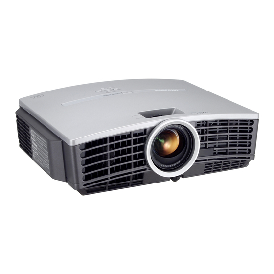
Preparing your projector Checking accessories The following accessories are provided with this projector. Check to be sure that all of the accessories are packed in the package. Cables Power supply parts Mini D-SUB D-SUB 9-pin 15-pin Mini D-SUB 8-pin 15-pin RS-232C cable RGB cable for PC Power cord... - Page 7 Overview 1 FOCUS ring 2 ZOOM ring 3 Control panel 4 Air outlet grille 5 Remote control sensor (Front) 6 Air inlet grille 7 Air outlet grille 8 Terminal board 9 Kensington Security Lock Standard connector 10 Air inlet grille Control area 1 POWER button 2 AUTO POSITION /...
-
Page 8: Remote Control
Preparating your projector (Continue) Bottom side 1 Adjustment foot (Front) 2 Lamp cover 3 Adjustment feet (Rear) Caution: Do not replace the lamp immediately after using the projector because the lamp would be extremely hot and it may cause burns. Remote control 1 ON ( ) button 2 DVI-D(HDCP) button... -
Page 9: Using The Remote Control
Using the remote control Operational range of the remote control • Keep the remote control photo-sensor out of direct sunlight or fl uorescent lamp light. • Keep the remote control photo-sensor at least 2 m away from fl uorescent lamps. Otherwise, the re- Front of projector Rear of projector mote control may malfunction. -
Page 10: Setting Up Your Projector
Setting up your projector Setting up the screen Install the screen perpendicularly to the projector. If the screen can not be installed in such a way, adjust the projection angle of the projector. (See below.) • Install the screen and projector so that the projector’s lens is placed at the same height and horizontal position of the screen center. - Page 11 Screen size and projection distance Refer to the following table to determine the screen size. Screen size Center of the lens (Width of the projected image) Projected distance (L) When the aspect ratio of the screen is 4:3, the positional relation between the projected image and Screen size the screen is as shown on the right.
-
Page 12: Viewing Video Images
Viewing video images A. Connecting the projector to video equipment Preparation: • Make sure that the power of the projector and that of the video equipment are turned off. Basic home theater system connection COMPONENT VIDEO IN S-VIDEO IN VIDEO IN Video player DVD player Set-top box or digital tuner... - Page 13 Connecting to a video player, etc. Video player, or the like 1. Connect one end of the optional video cable to the VIDEO IN terminal of the projector. 2. Connect the other end of the video cable to the video output terminal of the video equipment.
- Page 14 Viewing video images (continued) Connecting to video equipment having a DVI-D terminal You can project high-quality images by connecting the DVI-D terminal of this projector to video equipment having a DVI-D output terminal. In addition, this projector supports HDCP and is able to receive encrypted digital video data that are output from DVD players.
- Page 15 C. Projecting images Preparation: • Remove the lens cap. • Turn on the power of the connected video equipment. FOCUS ring COMPONENT button ZOOM ring ON ( I ) button VIDEO button S-VIDEO button POWER button POWER STATUS VIDEO button 1.
-
Page 16: Iris Button
Viewing video images (continued) OFF ( ) button POWER button POWER STATUS To stop projecting: 8. Press the POWER button on the projector or the OFF ( ) button on the remote control. • A confi rmation message is displayed. •... -
Page 17: Setting The Aspect Ratio
Setting the aspect ratio You can change the aspect ratio of the input video signal (or the ratio of width to height of the image). Change the setting according to the type of the input video signal. 4 : 3 16 : 9 EXPAND REAL*... -
Page 18: Viewing Computer Images
Viewing computer images A. Connecting the projector to a computer Preparation: • Make sure that the power of the projector and that of the computer are turned off. • When connecting the projector to a desktop computer, disconnect the RGB cables that are connected to the monitor. - Page 19 C. Projecting images Preparation: • Remove the lens cap. • Turn on the power of the connected computer. FOCUS ring ON ( I ) button ZOOM ring DVI-D(HDCP) button COMPUTER button POWER button POWER STATUS COMPUTER button 1. Confi rm the POWER indicator lights up red. •...
- Page 20 Viewing computer images (continued) OFF ( ) button POWER button POWER STATUS To stop projecting: 8. Press the POWER button on the projector or the OFF ( ) button on the remote control. • A confi rmation message is displayed. •...
-
Page 21: Menu Operation
Menu operation • Menus are not displayed when no signal is supplied to the projector. IMAGE CONTRAST ±30 BRIGHTNESS ±30 WHITE ENHANCE AUTO, 0 - 10 COLOR TEMP. HIGH BRIGHTNESS 9300K CONTRAST R ±30 6500K CONTRAST B ±30 5900K BRIGHTNESS R ±30 USER BRIGHTNESS B... - Page 22 Menu operation (continued) Available settings in the menus Set the following items on their relevant menus. 1. IMAGE menu 2. INSTALLATION menu 3. FEATURE menu 4. SIGNAL menu opt. opt. opt. opt. SVGA60 SVGA60 SVGA60 SVGA60 INSTALLATION AV MEMORY 1 IMAGE AV MEMORY 1 FEATURE...
- Page 23 3. FEATURE menu ITEM SETTING FUNCTION MENU POSITION 2 options Use to change the position of the menu. CINEMA MODE AUTO The fi lm mode will be automatically activated when a fi lm source signal is input. The fi lm mode will not be activated. VIDEO SIGNAL 8 options When AUTO is selected, the appropriate video format is automatically selected...
-
Page 24: Adjusting Projected Images
Adjusting projected images To adjust the brightness (CONTRAST and BRIGHTNESS): You can make adjustments for the brightness of the projected image using the menu. (See Page 21 for menu setting.) 1. Display the IMAGE menu. 2. Select CONTRAST or BRIGHTNESS by pressing the button. -
Page 25: About Color Temperature
To adjust the tone of white (COLOR TEMP.): You can select a preset color temperature (white tone) using the menu. (See Page 21 for menu setting.) 1. Display the IMAGE menu. 2. Select COLOR TEMP. by pressing the button. 3. Select your desired color temperature by pressing the button. - Page 26 Adjusting projected images (continued) This projector automatically and properly projects video signals supplied from the computer. However, some video signals may not be projected, depending on the type of the computer. In such a case, press the AUTO POSITION button. (See Page 20.) When the signal is still not projected properly, adjust the projected image using the SIGNAL menu.
-
Page 27: Advanced Features
Advanced features Password function To cancel the password function: This projector is equipped with the password function 1. Display the FEATURE menu. that is designed for prevention of wrong operation by 2. Press the button to select PASSWORD children and restriction on operation by other than FUNCTION. -
Page 28: Asking For Installation
Be sure to ask a certifi ed installation details. specialist for installation of the projector. Contact your dealer for details. • Mitsubishi assumes no responsibilities for any damage caused by use of other manufacturer's ceiling bracket and by inadequate installation conditions even within the warranty period. -
Page 29: Using Fi Lter
Using fi lter This projector has a fi lter cover (fi lter) for keeping dust out. When using the projector in a dusty place, attach this fi lter cover. Installation Before installing this fi lter to the projector, be sure to unplug the projector from the outlet. -
Page 30: Replacing The Lamp
Replacing the lamp This projector is equipped with a lamp to project images. This lamp is a consumable. It may burn out or its brightness may decrease during use. In such cases, replace the lamp with a new one as soon as possible. Be sure to replace the lamp with a new lamp separately sold that is exclusive to this projector. -
Page 31: Cleaning
To replace the lamp: 1. Reverse the projector gently. 2. Loosen the screw (a) using a Phillips screwdriver (+), and remove the lamp cover (b). 3. Loosen the screws (c) using a Phillips screwdriver (+). 4. Pull up the handle. 5. -
Page 32: Troubleshooting
Troubleshooting Before asking for repair of the projector, check the following. If the symptom persists, stop using the projector, be sure to unplug the power plug, and then contact your dealer. No image appears on the screen. Problem Solution Power can not be •... - Page 33 No image appears on the screen. (Continued) Problem Solution "NO SIGNAL" is • Turn on the power of the connected device, or check whether there is something wrong with the connected device. displayed. • Check whether the external device output signals. (Check this especially when the external device is a notebook computer.) •...
- Page 34 Troubleshooting (continued) Others Problem Solution The exhaust vents • This air comes out after cooling the inside of the projector. You may feel hot, but this is not a malfunction. emit warm air. • The microcomputers inside the projector may be wrongly operating because of noise. The menu can't be Press the POWER button to turn off the lamp and unplug the power cord from the used.
-
Page 35: Indicators
Indicators This projector has two indicators, each of which shows the operation condition of the projector. The following offer solutions to possible problems. If these problem persist, turn the projector off and consult your dealer. POWER indicator STATUS indicator Normal condition POWER STATUS CONDITION... -
Page 36: Specifi Cations
Specifi cations The specifi cations and outside appearance of the projector are subject to change without prior notice. DLP™ projector Type HC910 Model 0.65-inch Single chip DMD (Aspect ratio 16:9) Display Technology Pixel 1024 x 576 = 589824 pixels F 2.4 - 2.6 f= 23 - 27.6 mm Projection lens 200 W Light-source lamp... - Page 37 Specifi cation of RGB signals in each computer mode of the projector Signal mode Resolution Horizontal Vertical Normal mode Real mode (H x V) frequency (kHz) frequency (Hz) (H x V)*1 (H x V) TV60, 480i(525i) 15.73 59.94 1024 x 576 TV50, 576i(625i) 15.63 50.00...
- Page 38 Technical Inquiries :+886-2-2833-9813 Centro Direzionale Colleoni, Palazzo Persero-Ingresso 2, Phone :+852-2422-0161 Via Paracelso 12, 20041 Agrate Brianza, Italy MKY (Mitsubishi Electric Kang Yong Watana Co., Ltd. ) :+852-2487-0181 Sales & Technical Inquiries http://www.mitsubishi-kyw.co.th/ SINGAPORE (Mitsubishi Electric Asia Pte. Ltd.) Phone...
Need help?
Do you have a question about the DLP HC910 and is the answer not in the manual?
Questions and answers