Table of Contents
Advertisement
Operating and Installation instructions
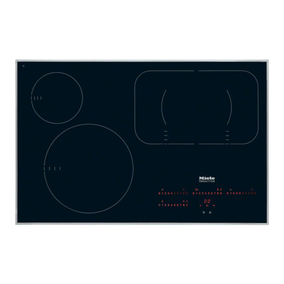
Ceramic hobs with induction
KM 5731 / KM 5732 / KM 5733
KM 5736 / KM 5737 / KM 5752
KM 5753 / KM 5755 / KM 5757
KM 5775
en - GB
To avoid the risk of accidents or
damage to the appliance it is
essential to read these
instructions before it is installed
and used for the first time.
M.-Nr. 06 661 920
Advertisement
Table of Contents

Related Manuals for Miele KM 5731


Summary of Contents for Miele KM 5731
- Page 1 Operating and Installation instructions Ceramic hobs with induction KM 5731 / KM 5732 / KM 5733 KM 5736 / KM 5737 / KM 5752 KM 5753 / KM 5755 / KM 5757 KM 5775 en - GB To avoid the risk of accidents or...
-
Page 2: Table Of Contents
KM 5731........ - Page 3 Contents Safety features ........... 34 Safety lock .
-
Page 4: Guide To The Appliance
Guide to the appliance KM 5731 abcd Cooking zones e Cooking zone controls and displays (see “Cooking zone controls and displays”) f Timer control and display (see “Timer control and display”) g Safety lock indicator lamp h Safety lock sensor switch... - Page 5 Guide to the appliance KM 5732 / KM 5736 / KM 5737 abcd Cooking zones e Cooking zone controls and displays (see “Cooking zone controls and displays”) f Timer control and display (see “Timer control and display”) g Safety lock indicator lamp h Safety lock sensor switch i Hob ON/OFF sensor switch...
- Page 6 Guide to the appliance KM 5733 abc Cooking zones e Cooking zone controls and displays (see “Cooking zone controls and displays”) f Timer control and display (see “Timer control and display”) g Safety lock indicator lamp h Safety lock sensor switch i Hob ON/OFF sensor switch...
- Page 7 Guide to the appliance KM 5752 / KM 5757 abcd Cooking zones e Cooking zone controls and displays (see “Cooking zone controls and displays”) f Timer control and display (see “Timer control and display”) g Safety lock indicator lamp h Safety lock sensor switch i Hob ON/OFF sensor switch...
- Page 8 Guide to the appliance KM 5753 abcd Cooking zones e Cooking zone controls and displays (see “Cooking zone controls and displays”) f Timer control and display (see “Timer control and display”) g Safety lock indicator lamp h Safety lock sensor switch i Hob ON/OFF sensor switch...
- Page 9 Guide to the appliance KM 5755 abcd Cooking zones e Cooking zone controls and displays (see “Cooking zone controls and displays”) f Timer control and display (see “Timer control and display”) g Safety lock indicator lamp h Safety lock sensor switch i Hob ON/OFF sensor switch...
- Page 10 Guide to the appliance KM 5775 abcd Cooking zones e Cooking zone controls and displays (see “Cooking zone controls and displays”) f Timer control and display (see “Timer control and display”) g Safety lock indicator lamp h Safety lock sensor switch i Hob ON/OFF sensor switch...
-
Page 11: Cooking Zone Sensors And Displays
Guide to the appliance Cooking zone sensors and displays j Displays: = Cooking zone ready for use 1 to 9 = Power settings (for switched on hob) = Residual heat ß = No pan on cooking zone or pan unsuitable (see "Induction") = Fault (see "Safety switch-off") = Auto heat-up when the power setting range has been extended... -
Page 12: Timer Control And Display
Indicator lamp for automatic switch-off, e.g. of the rear right cooking zone s Indicator lamp for minute minder Cooking zones Cooking KM 5731 / KM 5752 / KM 5755 / KM 5757 zone minimum to maximum Rating in watts for 230 V** Ø... - Page 13 Guide to the appliance Cooking KM 5732 / KM 5736 zone minimum to maximum Rating in watts for 230 V** Ø in cm* 14 - 20 normal: 1850 with booster: 2500 10 - 16 normal: 1400 with booster: 1800 16 - 23 normal: 2300 with booster:...
- Page 14 Guide to the appliance Cooking KM 5737 zone minimum to maximum Rating in watts for 230 V** Ø in cm* 14 - 20 normal: 1850 with booster: 2500 10 - 16 normal: 1400 with booster: 1800 16 - 23 normal: 2300 with booster: 3200...
- Page 15 Guide to the appliance Cooking zone KM 5775 minimum to maximum Rating in watts for 230 V** Ø in cm* 16 - 23 normal: 2300 with booster: 3200 10 - 16 normal: 1400 with booster: 1800 14 - 20 normal: 1850 with booster: 2500...
-
Page 16: Warning And Safety Instructions
Warning and Safety instructions Technical safety To avoid the risk of accidents and The appliance must be installed and damage to the appliance, please connected by a suitably qualified and read these instructions carefully competent person in strict accordance before using it for the first time. They with current local and national safety contain important notes on its regulations. - Page 17 Warning and Safety instructions Correct usage Never open the casing of the appliance. For safety reasons this appliance Tampering with electrical connections must only be operated after it has been or components is highly dangerous to built in. This is necessary to ensure that the user and can cause operational all electrical components are shielded.
- Page 18 Warning and Safety instructions Safety with children Keep all pans out of reach of children. Turn pan handles inwards Use the safety lock to prevent away from the edge of the hob. Danger children operating the appliance or of burning or scalding. Special hob altering the settings.
- Page 19 Warning and Safety instructions Protecting the appliance from Never place hot pans near the control area. This could damage the damage electronic unit underneath. Do not drop anything on the ceramic This hob is fitted with a cooling fan. surface. Even a light object could If a drawer is fitted directly underneath cause damage in certain the hob, ensure that there is sufficient...
- Page 20 Warning and Safety instructions Protection from burning and Do not cover the appliance, e.g. with a cloth, kitchen foil, etc. This could scalding be a fire hazard if the appliance is The appliance gets hot when in use switched on by mistake. and remains hot for quite a while after Never leave the appliance being switched off.
- Page 21 While the appliance is under socket and withdraw the plug. Contact guarantee, repairs should only be the Miele Service Department. undertaken by a service engineer Do not reconnect the appliance to the authorised by the manufacturer.
- Page 22 Warning and Safety instructions Futher safety notes Do not use plastic or aluminium foil containers. These melt at high For people fitted with a heart temperatures and could damage the pacemaker: ceramic surface. Fire hazard. Please note that the area immediately surrounding the hob is To prevent damage to items which electromagnetically charged, and that...
-
Page 23: Caring For The Environment
Caring for the environment Disposal of the packing Disposal of your old appliance material Electrical and electronic appliances often contain materials which, if The transport and protective packing handled or disposed of incorrectly, has been selected from materials which could be potentially hazardous to are environmentally friendly for human health and to the environment. -
Page 24: Before Using For The First Time
Before using for the first time Heating up for the first time Please stick the extra data plate for the appliance supplied with this On hobs with bevelled glass edges, documentation in the space provided in a small gap may be visible between the "After sales service"... -
Page 25: Induction
Induction How it works If a suitable pan is placed on the cooking zone within 3 minutes, the ß An induction coil is located under each will go out and you can continue as cooking zone. When a cooking zone is normal. -
Page 26: Noises
Induction Noises The appliance has a cooling fan to help extend the life of the electronics. When When using an induction cooking zone, the hob is being used intensively, this the following noises can occur in the will come on and you will hear a pan, depending on what it is made of whirring sound. -
Page 27: Pans
Induction Pans Pan size Suitable pans include: To make optimum use of the cooking zones, choose pans with diameters – stainless steel pans with a magnetic larger than the innermost markings but base smaller than the outermost markings. If – enamelled steel pans the diameter of the pan is smaller than the innermost marking, the induction –... -
Page 28: Sensor Switches
Operation Sensors Switching on This hob is equipped with electronic The hob must be switched on before sensors which react to finger contact. any of the zones can be used. To operate a cooking zone, touch the Do not leave the appliance relevant sensor. -
Page 29: Settings
Operation Settings Cooking process Settings* standard extended factory settings settings** (9 settings) (17 settings) Melting butter 1 - 2 1 - 2. Dissolving gelatine Warming small quantities of food/liquid 3 - 3. Keeping warm food which sticks easily Cooking rice Defrosting frozen vegetables Warming liquid and semi-solid foods 4 - 4. -
Page 30: Auto Heat-Up
Operation Auto heat-up When Auto heat-up has been activated, Continued Heat-up time the cooking zone switches on cooking setting* in minutes and automatically at the highest setting and seconds then switches to the continued cooking (approx.) setting which you have previously selected. - Page 31 Operation How to activate Auto heat-up At any point during the Auto heat-up time you can use - or + to lower or ^ Press the - sensor until the required increase the continued cooking setting. continued cooking setting appears, The Auto heat-up time will alter e.g.
-
Page 32: Booster Function
Operation Booster function When the booster is switched on, the following happens: All of the cooking zones are equipped with a booster function, i. e. an increase – if Auto heat-up is activated on either in the power level. zone in the same network, this will be If activated, the zones will operate on switched off. -
Page 33: Switching Off And Residual Heat Indicators
Operation Switching off and residual heat The lines of the residual heat indicator go out one after another as the cooking indicators zones cool down. The last horizontal line only goes out when the cooking To switch off a cooking zone: zone is safe to touch. -
Page 34: Safety Features
Safety features Safety lock To activate the safety lock: ^ Touch the safety lock sensor $ until Keep children away from the hob for their own safety. the relevant indicator lamp comes on. Your appliance is equipped with a The indicator lamp will go out after a safety lock to prevent the hob and the short while. -
Page 35: Stop And Go
Safety features Stop and Go To deactivate Stop and Go: ^ Touch the $ sensor until the indicator Your appliance has a Stop and Go feature which, when activated, reduces lamp goes out. the power of all switched on cooking The cooking zones will now run at the zones to setting 1. -
Page 36: Safety Switch-Off
Safety features Safety switch-off Safety switch-off if the sensors are covered Safety switch-off with an over-long Your hob will switch off automatically if cooking time one or several of the sensors remain covered for longer than 10 seconds, for Your hob is fitted with a safety switch-off feature in case you forget to example, by finger contact, food boiling switch it off yourself. -
Page 37: Overheating Protection
Safety features Overheating protection Overheating can be caused by: All of the induction coils and the cooling – heating up an empty pan element for the electronics are fitted – fats or oils being heated up on the with an overheating protection highest power setting. -
Page 38: Timer
Timer Setting the minute minder The hob is fitted with a timer which can be used both as a minute minder and The minute minder can be used with to switch off the cooking zones the hob switched on or off. It works like automatically. -
Page 39: Switching A Cooking Zone Off Automatically
Timer Switching a cooking zone off ^ Touch the - or + sensor until the time you require appears in the display, automatically e.g. 15 minutes. It is only possible to programme a cooking zone to switch off automatically if a power setting has already been selected for that zone. -
Page 40: Combi Mode
Timer Combi mode Timer factory settings The minute minder and automatic The timer is set at the factory so that it starts with 01 or 99 when the + or - switch-off functions can be used at the same time. sensor is touched. -
Page 41: Cleaning And Care
Cleaning and care For Miele branded cleaning and The appliance should be cleaned after conditioning products see "Optional each use. Allow the hob to cool down accessories". before cleaning. Wipe all coarse soiling off using a Do not use a steam cleaner to clean damp cloth. - Page 42 Cleaning and care Spots caused by limescale deposits, Should any sugar, plastic or water and aluminium residues (which aluminium foil spill or fall on to a hot have a metalic appearance) can be cooking zone while it is in use, first removed using the ceramic cleaner.
-
Page 43: Programming
Programming You can change the standard settings To store the new settings in memory, touch the hob ON/OFF sensor s until of your hob (see chart). the displays go out. Proceed as follows: If you do not wish to store the settings in memory, touch the safety lock sensor ^ With the hob switched off, touch the $ until the displays go out. - Page 44 Programming Programme* Status** Setting Demonstration mode and Demonstration mode on factory default settings Demonstration mode off Factory default settings reinstated Keypad tone when a sensor is touched Induction warning tone when there is no pan or the pan is unsuitable Audible tone for the Timer S Audible tone on for 10 seconds Audible tone on for 4 minutes...
- Page 45 Programming Programme* Status** Setting Auto heat-up Activated by selecting the power setting using - Activated by selecting the power setting using + Activated every time the hob is switched on H as the residual heat Residual heat indicator indicator symbol # as the residual heat indicator symbol Timer factory settings...
-
Page 46: Problem Solving Guide
– switch off at the mains, or – withdraw the mains fuse. Reset the trip switch in the mains fuse box, and switch the appliance back on. If it still will not switch on, contact a qualified electrician or the Miele Service Department. - Page 47 1 minute. highest setting and then turn down to a lower setting manually later on. If the problem persists after reconnecting the appliance to the power supply, please contact the Miele Service department.
-
Page 48: After Sales Service, Data Plate
– Your Miele dealer, or – the Miele Customer Contact Centre (see back cover for address). When contacting Miele, please quote the model and serial number of your appliance. These are given on the data plate. Please note that telephone calls may be monitored and recorded to improve our service. -
Page 49: Installation
Installation Safety instructions for After installing the hob, ensure that the connection cable cannot come into installation contact with the underside of the appliance. Make sure that there is no Fit wall units and extractor hood mechanical obstruction, such as a before fitting the hob to avoid drawer, which could damage it. - Page 50 Installation Safety distance above the hob When two or more appliances are installed together below a cooker hood, e.g. an electric hob and a gas wok combiset, which have different safety distances given in the installation instructions, you should select the greater distance of the two.
- Page 51 Installation Safety distances to the sides of the Ideally the hob should be installed with plenty of space on either side. There may be a wall at the rear and a tall unit or wall at one side. On the other side, however, no unit or divider should stan- d higher than the hob (see illustrations).
- Page 52 Installation Safety distance when installing the appliance near a wall with additional niche cladding There must be a minimum distance of 50 mm between the niche cladding and the worktop cut-out. This distance is only necessary for niche cladding made of wood or any other combustible material.
-
Page 53: Installation Above An Oven
Induction hob fan a back panel. d Distance between the front edge of When installed above a Miele oven the fan and the worktop cut-out in a worktop thickness 0 40 mm the (depending on the type of hob) -
Page 54: Hob With Frame Or Bevelled Edge
Installation Hob with frame or bevelled edge Building-in dimensions for KM 5731 a Front b Building-in depth c Building-in depth for mains connection cable d Mains connection cable, L = 1440 mm... - Page 55 Installation Building-in dimensions for KM 5732 5 0 4 5 7 4 ß 4 9 0 4 7 5 2 0 3 4 2 2 a Front b Building-in depth c Mains connection cable, L = 1440 mm...
- Page 56 Installation Building-in dimensions for KM 5733 a Front b Building-in depth c Building-in depth for mains connection cable d Mains connection cable, L = 1440 mm...
- Page 57 Installation Building-in dimensions for KM 5736 a Front b Building-in depth c Mains connection cable, L = 1440 mm...
- Page 58 Installation Building-in dimensions for KM 5752 5 0 4 7 6 4 ß R4 4 9 0 4 7 5 2 0 3 4 2 2 a Front b Building-in depth c Mains connection cable, L = 1440 mm...
- Page 59 Installation Building-in dimensions for KM 5753 a Front b Building-in depth c Building-in depth for mains connection cable d Mains connection cable, L = 1440 mm...
- Page 60 Installation Building-in dimensions for KM 5755 8 9 0 5 1 0 4 6 , 5 8 5 2 ß 4 9 0 4 7 5 2 0 3 46,5 4 2 2 a Front b Building-in depth c Mains connection cable, L = 1440 mm...
- Page 61 Installation Building-in dimensions for KM 5775 a Front b Building-in depth c Building-in depth for mains connection cable d Mains connection cable, L = 1440 mm...
- Page 62 Installation Preparing the worktop Installing the hob ^ Make the worktop cut-out following ^ Feed the hob connection cable down the dimensions applicable. through the cut-out. Remember to maintain a minimum ^ Place the hob centrally in the cut-out. safety distance of 50 mm from the When doing this make sure that the back wall, as well as from any tall unit seal under the hob sits flush with the...
-
Page 63: Sealant
Installation Sealant Do not use any sealant unless expressly instructed to do so. The sealing strip under the edge of the top part of the hob provides a sufficient seal for the worktop. Do not use sealant between the frame of the top part of the hob and the worktop. -
Page 64: Flush-Fitted Hobs
Installation Flush-fitted hobs Building-in dimensions for KM 5737 a Front Cut-out dimensions for granite or marble worktops. b Building-in depth Please take careful note of the inset c Mains connection cable, diagram. L = 1440 mm d Stepped cut-out for granite or marble worktops... - Page 65 Installation Building-in dimensions for KM 5757 4 9 0 7 5 0 ß 4 7 0 4 9 6 4 7 5 2 0 3 4 2 2 a Front Cut-out dimensions for granite or marble worktops. b Building-in depth Please take careful note of the inset c Mains connection cable, diagram.
- Page 66 Installation The hob can be installed Flush fit hobs are only suitable for – directly into a suitable cut-out in a installation in granite, marble, tiled or granite or marble worktop. solid wood worktops. Other materials such as Corian and –...
- Page 67 Installation ^ Make the worktop cut-out as shown Making the worktop cut-out and in the drawings. building in the hob ^ Feed the hob connection cable down Granite and marble worktops through the cut-out. ^ Centre the hob f in the cut-out. 0 50 ^ Connect the hob to the mains.
- Page 68 Installation ^ Make the worktop cut-out as shown Solid wood and tiled worktops in drawings. ^ Fix the wooden frame a 7mm below 0 50 the top edge of the worktop (see diagram). ^ Feed the hob connection cable down through the cut-out.
-
Page 69: Electrical Connection
(including switch, type H 05 W-F or H 05 RR-F, fuses and relays). available from the Miele Customer Contact Centre. Important U.K. The appliance is supplied for Ensure power is not supplied to the... - Page 70 Installation WARNING THIS APPLIANCE MUST BE EARTHED The electrical safety of this appliance can only be guaranteed when continuity is complete between it and an effective earthing system, which complies with current local and national safety regulations. It is most important that this basic safety requirement is present and regularly tested and where there is any doubt, the electrical wiring...
-
Page 71: Wiring Diagram
Installation Wiring diagram N.B. This appliance is supplied single phase only in the U.K. / AUS / NZ... - Page 72 Alteration rights reserved / 4207 M.-Nr. 06 661 920 / 04...
Need help?
Do you have a question about the KM 5731 and is the answer not in the manual?
Questions and answers