Table of Contents
Advertisement
Quick Links
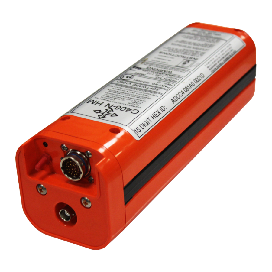
EMERGENCY LOCATOR TRANSMITTER
Abbreviated Component Maintenance Manual
This manual includes data for the equipment that follows:
Component
Emergency Locator Transmitter
Emergency Locator Transmitter
C406-N SERIES
Part No.
453-5060
453-5061
25-62-13
Model No.
C406-N
C406-N HM
Wulfsberg Electronics Division
6400 Wilkinson Rd., Prescott, AZ 86301
Cage Code: 1B7G3
570-5060 Rev. F
Initial Issue MAY 12/2003
Page 1 of 110
JAN 24/11
Advertisement
Table of Contents
Troubleshooting

Related Manuals for COBHAM C406-N Series


Summary of Contents for COBHAM C406-N Series
- Page 1 C406-N SERIES EMERGENCY LOCATOR TRANSMITTER Abbreviated Component Maintenance Manual This manual includes data for the equipment that follows: Component Part No. Model No. Emergency Locator Transmitter 453-5060 C406-N Emergency Locator Transmitter 453-5061 C406-N HM Wulfsberg Electronics Division 6400 Wilkinson Rd., Prescott, AZ 86301...
- Page 2 COBHAM AVIONICS WULFSBERG ELECTRONICS ABBREVIATED COMPONENT MAINTENANCE MANUAL C406-N (453-5060), C406-N HM (453-5061) PROPRIETARY INFORMATION This document contains proprietary information and such information may not be disclosed to others for any purpose, nor used for manufacturing purposes without written permission from Wulfsberg Electronics.
-
Page 3: Record Of Revisions
COBHAM AVIONICS WULFSBERG ELECTRONICS ABBREVIATED COMPONENT MAINTENANCE MANUAL C406-N (453-5060), C406-N HM (453-5061) RECORD OF REVISIONS REV NO. DCN NO. DCN DATE REV NO. DCN NO. DCN DATE RELEASE May 12/2003 DCN 2227 Jul 11/2003 DCN 2273 Sep 08/2003 DCN 2380... - Page 4 COBHAM AVIONICS WULFSBERG ELECTRONICS ABBREVIATED COMPONENT MAINTENANCE MANUAL C406-N (453-5060), C406-N HM (453-5061) THIS IS A BLANK PAGE 25-62-13 Page 4 of 110 JAN 24/11...
-
Page 5: Service Bulletin List
COBHAM AVIONICS WULFSBERG ELECTRONICS ABBREVIATED COMPONENT MAINTENANCE MANUAL C406-N (453-5060), C406-N HM (453-5061) SERVICE BULLETIN LIST SERVICE ISSUE MANUAL MANUAL SUBJECT BULLETIN NO DATE REV NO REV DATE 25-62-13 Page 5 of 110 JAN 24/11... - Page 6 COBHAM AVIONICS WULFSBERG ELECTRONICS ABBREVIATED COMPONENT MAINTENANCE MANUAL C406-N (453-5060), C406-N HM (453-5061) THIS IS A BLANK PAGE 25-62-13 Page 6 of 110 JAN 24/11...
-
Page 7: List Of Effective Pages
COBHAM AVIONICS WULFSBERG ELECTRONICS ABBREVIATED COMPONENT MAINTENANCE MANUAL C406-N (453-5060), C406-N HM (453-5061) LIST OF EFFECTIVE PAGES SUBJECT PAGE DATE SUBJECT PAGE DATE Title Page Jan 24/11 Description and Operation Jan 24/11 Notices Jan 24/11 (cont.) Jan 24/11 Record of Revisions... - Page 8 COBHAM AVIONICS WULFSBERG ELECTRONICS ABBREVIATED COMPONENT MAINTENANCE MANUAL C406-N (453-5060), C406-N HM (453-5061) SUBJECT PAGE DATE SUBJECT PAGE DATE Installation (cont.) Jan 24/11 Appendix B (cont.) Jan 24/11 Jan 24/11 BLANK Jan 24/11 Appendix C Jan 24/11 Jan 24/11 Jan 24/11...
-
Page 9: Table Of Contents
A. C406-N and C406-N HM ........ - Page 10 ABBREVIATED COMPONENT MAINTENANCE MANUAL C406-N (453-5060), C406-N HM (453-5061) C. Antennas ............38 Table 4.
- Page 11 COBHAM AVIONICS WULFSBERG ELECTRONICS ABBREVIATED COMPONENT MAINTENANCE MANUAL C406-N (453-5060), C406-N HM (453-5061) INSTALLATION 1. Regulatory Requirements and Guidelines ......... 57 A.
- Page 12 COBHAM AVIONICS WULFSBERG ELECTRONICS ABBREVIATED COMPONENT MAINTENANCE MANUAL C406-N (453-5060), C406-N HM (453-5061) APPENDIX A – ELT REGISTRATION 1. Background Information ........... . 83 A.
- Page 13 COBHAM AVIONICS WULFSBERG ELECTRONICS ABBREVIATED COMPONENT MAINTENANCE MANUAL C406-N (453-5060), C406-N HM (453-5061) ILLUSTRATED PARTS LIST 1. Introduction ............101 A.
- Page 14 COBHAM AVIONICS WULFSBERG ELECTRONICS ABBREVIATED COMPONENT MAINTENANCE MANUAL C406-N (453-5060), C406-N HM (453-5061) THIS IS A BLANK PAGE 25-62-13 Page 14 of 110 JAN 24/11...
-
Page 15: List Of Figures
Figure 2. C406-N Series ELT and Mounting Frame Assembly ....... 30 Figure 3. - Page 16 Figure 36. C406-N Series ELT Main Assembly and Installation .......105...
-
Page 17: Introduction
Installation Registration Illustrated Parts List In the United States, the C406-N Series ELT must be installed and maintained in accordance with the requirements herein and 14 CFR, FAR Parts 43, and 91; and other airworthiness requirements, as applicable. In Canada, the C406-N Series ELT must be installed and maintained in accordance with the requirements herein and Canadian Aviation Regulations (CAR), Part V, Paragraph 551.104 and... - Page 18 ABBREVIATED COMPONENT MAINTENANCE MANUAL C406-N (453-5060), C406-N HM (453-5061) C406-N Series ELT installation and maintenance in all other countries must comply with the requirements herein and applicable national airworthiness requirements. The accessories (i.e., remote switch and antennas) addressed in this manual are the accessories most commonly associated with the C406-N Series ELT.
-
Page 19: Model Descriptions
2. Model Descriptions SUBTASK 25-62-13-990-001 C406-N The C406-N is a type AF (Automatic Fixed) ELT, which transmits on 121.5, 243.0, and 406 MHz. The ELT is enclosed within a multi-piece mounting frame consisting of a mounting tray, protective top cover and mounting frame cap. -
Page 20: Approvals
LITHIUM BATTERY SAFETY CONCERNS INCLUDE THE POSSIBILITY OF FIRE, VENTING VIOLENTLY, AND VENTING OF TOXIC GASES. The lithium battery pack used on the C406-N Series ELT is certified under TSO C142. NOTE: Details of TSO certification are available in the “452-0133 - 406 Lithium Battery Pack TSO C142 Report”... -
Page 21: Table 1. Environmental Categories Breakdown
COBHAM AVIONICS WULFSBERG ELECTRONICS ABBREVIATED COMPONENT MAINTENANCE MANUAL C406-N (453-5060), C406-N HM (453-5061) Table 1. Environmental Categories Breakdown CATEGORY SECTION DESCRIPTION Temperature/Altitude 4.5.4 In-Flight Loss of Cooling Temperature Variation Humidity B204 Operational Shock and Crash Safety Vibration Explosion 10.0 Waterproofness 11.0... -
Page 22: Frequency Allocations
SUBTASK 25-62-13-990-002 Discussion The 406 MHz transmitter frequency of the C406-N Series ELT was originally 406.028 MHz. In order to comply with COSPAS-SARSAT frequency allocation requirements, changes to the 406 MHz frequency may occur since the original release of this product. -
Page 23: List Of Acronyms, Abbreviations, And Definitions
COBHAM AVIONICS WULFSBERG ELECTRONICS ABBREVIATED COMPONENT MAINTENANCE MANUAL C406-N (453-5060), C406-N HM (453-5061) TASK 25-62-13-990-805 5. List of Acronyms, Abbreviations, and Definitions SUBTASK 25-62-13-990-001 Term Definition Advisory Circular – A Federal Aviation Administration (USA) bulletin with special information. For the purposes of this document, the acro- nym AC does not refer to electrical alternating current. - Page 24 COBHAM AVIONICS WULFSBERG ELECTRONICS ABBREVIATED COMPONENT MAINTENANCE MANUAL C406-N (453-5060), C406-N HM (453-5061) EUROCAE European Organization for Civil Aviation Equipment – EUROCAE docu- ments are widely referenced as a means of compliance to European Technical Standard Orders (ETSOs) and other regulatory documents.
- Page 25 COBHAM AVIONICS WULFSBERG ELECTRONICS ABBREVIATED COMPONENT MAINTENANCE MANUAL C406-N (453-5060), C406-N HM (453-5061) RTCA Radio Technical Commission for Aeronautics – Organization that makes recommendations for airworthiness. Refer to http:// www.rtca.org/aboutrtca.asp for more information. A rubbery silicon-based adhesive typically used to prevent vibration problems and water intrusion.
-
Page 26: References
COBHAM AVIONICS WULFSBERG ELECTRONICS ABBREVIATED COMPONENT MAINTENANCE MANUAL C406-N (453-5060), C406-N HM (453-5061) TASK 25-62-13-990-806 6. References SUBTASK 25-62-13-990-001 Regulatory Documents The following regulatory documents are referred to herein. When referring to such documents, it is the manual user’s responsibility to ensure they are using the latest revision or release of such documents. -
Page 27: Other Documents
COBHAM AVIONICS WULFSBERG ELECTRONICS ABBREVIATED COMPONENT MAINTENANCE MANUAL C406-N (453-5060), C406-N HM (453-5061) DO-182, “Emergency Locator Transmitter (ELT) Equipment Installation and Performance” DO-183, “Minimal Operational Performance Standards for Emergency Locator Transmitters - Automatic Fixed-ELT (AF), Automatic Portable-ELT (AP), Automatic Deployable-ELT (AD), Survival-ELT (S) Operating on 121.5 and 243.0 MHz”... - Page 28 COBHAM AVIONICS WULFSBERG ELECTRONICS ABBREVIATED COMPONENT MAINTENANCE MANUAL C406-N (453-5060), C406-N HM (453-5061) THIS IS A BLANK PAGE 25-62-13 Page 28 of 110 JAN 24/11...
-
Page 29: Description And Operation
Aircraft identification (24-bit address) or registration number, and NOTE: When the optional C406-N Programming Adapter (PA) is installed, ELTs can be moved between aircraft and the PA reprograms the ELT with either the aircraft 24-bit address or registration number. See Appendix B – Programming Adapter Option, on page 85. -
Page 30: Components
SUBTASK 25-62-13-870-002 Components The C406-N Series ELT main assembly is housed in a high impact, fire resistant, polycarbonate plastic case, which is enclosed in a protective mounting frame assembly made of similar material. See "Figure 2. C406-N Series ELT and Mounting Frame Assembly". -
Page 31: Figure 3. Cockpit Remote Switch
Buzzer". Figure 4. Buzzer The battery pack for the C406-N Series ELT consists of four “D” size lithium manganese dioxide cells connected in series. In an effort to increase the safety of the battery pack, a number of features were designed into the battery pack. To prevent the cells from being charged, diodes are connected across each cell and fuses are connected to the output. -
Page 32: Figure 6. Rod And Whip Antennas
ABBREVIATED COMPONENT MAINTENANCE MANUAL C406-N (453-5060), C406-N HM (453-5061) Four single-input antennas are approved for use with the C406-N Series ELT. Selection of the proper antenna is dependent upon end use, aircraft configuration and speed, and other factors. See "Figure 6. Rod and Whip Antennas" and "Figure 7. Blade Antennas". -
Page 33: Operation
See "Figure 8. ELT Operational Flow Diagram". A primary feature of the C406-N Series ELT is its simplicity of operation. As long as the ELT is connected to the remote switch harness ELT connector, such that pins 12 and 13 are jumpered (G-switch loop), it will activate in the event of a crash. -
Page 34: Normal Operation
COBHAM AVIONICS WULFSBERG ELECTRONICS ABBREVIATED COMPONENT MAINTENANCE MANUAL C406-N (453-5060), C406-N HM (453-5061) The ELT is considered to be either “ACTIVE” or “INACTIVE”. When “INACTIVE”, the ELT is in a state of rest and performs no functions. Taking the ELT from the “INACTIVE” state to the “ACTIVE”... -
Page 35: Functional Check
COBHAM AVIONICS WULFSBERG ELECTRONICS ABBREVIATED COMPONENT MAINTENANCE MANUAL C406-N (453-5060), C406-N HM (453-5061) Reset the ELT locally by moving the switch on the ELT to the “ON” position, waiting approximately one second, and then moving it back to the “OFF” position. If the switch is already in the “ON”... -
Page 36: Specifications
3. Specifications SUBTASK 25-62-13-870-001 Environmental and Physical Table 2 lists the environmental and physical specifications of the C406-N Series ELT. NOTE: For automatic activation, the higher threshold of 4.5 ft/sec (2.3 g) is specified in accordance with Eurocae ED-62. Use of the higher threshold crash sensor has been approved by the FAA as a deviation to TSO C126 (FAA Reference #98-130S-108, February 6, 1998). -
Page 37: Electrical
COBHAM AVIONICS WULFSBERG ELECTRONICS ABBREVIATED COMPONENT MAINTENANCE MANUAL C406-N (453-5060), C406-N HM (453-5061) SUBTASK 25-62-13-870-002 Electrical Table 3 lists the electrical specifications of the C406-N Series ELT. Table 3. Electrical Specifications CRITERIA PARAMETER CHARACTERISTIC ± 1 KHz (Initial) 406.028 MHz, or higher... -
Page 38: Antennas
COBHAM AVIONICS WULFSBERG ELECTRONICS ABBREVIATED COMPONENT MAINTENANCE MANUAL C406-N (453-5060), C406-N HM (453-5061) SUBTASK 25-62-13-870-003 Antennas Table 4 lists the specifications of the antennas approved for use with the C406-N Series ELT. Table 4. Antenna Specifications CHARACTERISTIC PARAMETERS 110-338 110-340... -
Page 39: Test And Fault Isolation
COBHAM AVIONICS WULFSBERG ELECTRONICS ABBREVIATED COMPONENT MAINTENANCE MANUAL C406-N (453-5060), C406-N HM (453-5061) TEST AND FAULT ISOLATION TASK 25-62-13-750-801 1. Inspection and Test Regulatory Requirements SUBTASK 25-62-13-990-001 United States In accordance with FAR Part 91, Subpart C, § 91.207 (d), the ELT must be inspected within 12 calendar months after the last inspection for: Proper installation;... -
Page 40: Other Countries
COBHAM AVIONICS WULFSBERG ELECTRONICS ABBREVIATED COMPONENT MAINTENANCE MANUAL C406-N (453-5060), C406-N HM (453-5061) SUBTASK 25-62-13-990-003 Other Countries For all other countries, maintenance and testing shall be conducted in accordance with the requirements of applicable national regulatory authorities and the requirements herein, as applicable. -
Page 41: Inspection And Test Procedures
COBHAM AVIONICS WULFSBERG ELECTRONICS ABBREVIATED COMPONENT MAINTENANCE MANUAL C406-N (453-5060), C406-N HM (453-5061) TASK 25-62-13-750-802 2. Inspection and Test Procedures SUBTASK 25-62-13-990-001 Checklist Table 5 provides a list of the ELT inspection and testing requirements, a copy of which may be used as a checklist to verify inspection and test completion. -
Page 42: Preparation
COBHAM AVIONICS WULFSBERG ELECTRONICS ABBREVIATED COMPONENT MAINTENANCE MANUAL C406-N (453-5060), C406-N HM (453-5061) SUBTASK 25-62-13-000-001 Preparation Remove the ELT in accordance with SUBTASK 25-62-13-010-001, on page 53. Remove the battery pack in accordance with SUBTASK 25-62-13-050-001, on page 54. SUBTASK 25-62-13-220-001 Coax Cable and Wiring Connections Inspection –... -
Page 43: G-Switch Functional Check - Item 4
AC 43.13-1, Chapter 12, § 12-22, Note 3. Notify any nearby control tower of your intentions. Install the C406-N Test Loop Back Plug (151-5060) on the ELT receptacle or a jumper between Pins 12 and 13 of the ELT receptacle. -
Page 44: 121.5 Mhz Frequency Measurement - Item 5A
COBHAM AVIONICS WULFSBERG ELECTRONICS ABBREVIATED COMPONENT MAINTENANCE MANUAL C406-N (453-5060), C406-N HM (453-5061) Place the ELT in a container or screen room capable of substantially attenuating RF signals, or the transmitter power output shall be connected to a suitable dummy load to minimize radiation. -
Page 45: 121.5/243.0 Mhz Power Output Measurement - Item 5C
COBHAM AVIONICS WULFSBERG ELECTRONICS ABBREVIATED COMPONENT MAINTENANCE MANUAL C406-N (453-5060), C406-N HM (453-5061) SUBTASK 25-62-13-750-005 121.5/243.0 MHz Power Output Measurement – Item 5c Connect the measuring device, referring to SUBTASK 25-62-13-750-002, on page 43. Activate the ELT, if necessary, by placing the control switch in the “ON” position. -
Page 46: Current Draw Test - Item 5F
COBHAM AVIONICS WULFSBERG ELECTRONICS ABBREVIATED COMPONENT MAINTENANCE MANUAL C406-N (453-5060), C406-N HM (453-5061) SUBTASK 25-62-13-750-008 M. Current Draw Test – Item 5f CAUTION: EXERCISE EXTREME CAUTION TO AVOID CAUSING A SHORT CIRCUIT CONDITION, WHICH WILL BLOW THE FUSES IN THE BATTERY PACK. THIS TEST SHOULD ONLY BE PERFORMED BY AN EXPERIENCED TECHNICIAN/MECHANIC. -
Page 47: Digital Message Verification - Item 5G
COBHAM AVIONICS WULFSBERG ELECTRONICS ABBREVIATED COMPONENT MAINTENANCE MANUAL C406-N (453-5060), C406-N HM (453-5061) Allow the ELT to stabilize for at least 30 seconds to avoid false readings. Read the current draw on the ammeter. Steady state current draw must not exceed 200 mA. -
Page 48: Elt Reset Check - Item 5H
COBHAM AVIONICS WULFSBERG ELECTRONICS ABBREVIATED COMPONENT MAINTENANCE MANUAL C406-N (453-5060), C406-N HM (453-5061) SUBTASK 25-62-13-750-010 ELT Reset Check – Item 5h Place the ELT control switch in the “ON” position. Return the switch to the “OFF” position. If the ELT is working properly, the LED will stay on for approximately 1 second and then turn off. -
Page 49: Antenna Test - Item 7
COBHAM AVIONICS WULFSBERG ELECTRONICS ABBREVIATED COMPONENT MAINTENANCE MANUAL C406-N (453-5060), C406-N HM (453-5061) SUBTASK 25-62-13-750-012 Antenna Test – Item 7 CAUTION: Do not allow the duration of this test to exceed 5 seconds. Tune a low quality AM receiver (i.e., radio) to 121.5 MHz. -
Page 50: Fault Isolation
COBHAM AVIONICS WULFSBERG ELECTRONICS ABBREVIATED COMPONENT MAINTENANCE MANUAL C406-N (453-5060), C406-N HM (453-5061) TASK 25-62-13-810-801 3. Fault Isolation SUBTASK 25-62-13-810-001 Self-Test Error Troubleshooting Guidelines Table 6 describes the ELT self-test LED error codes (i.e., flash codes), their probable causes, and possible solutions. The 5-flash error is not present when the ELT is programmed with a serial user protocol (short message). - Page 51 COBHAM AVIONICS WULFSBERG ELECTRONICS ABBREVIATED COMPONENT MAINTENANCE MANUAL C406-N (453-5060), C406-N HM (453-5061) CODE PROBABLE CAUSE POSSIBLE SOLUTION Check with a VSWR meter. Check antenna Antenna or installation faulty for opens, shorts, or a resistive ground plane connection Lengthen or shorten antenna coax cable...
-
Page 52: Elt Troubleshooting Guidelines
COBHAM AVIONICS WULFSBERG ELECTRONICS ABBREVIATED COMPONENT MAINTENANCE MANUAL C406-N (453-5060), C406-N HM (453-5061) SUBTASK 25-62-13-810-002 ELT Troubleshooting Guidelines Table 7 provides ELT troubleshooting guidelines for installation and operational issues. Table 7. ELT Troubleshooting Guide SYMPTOM PROBABLE CAUSE POSSIBLE SOLUTION Improper wiring... -
Page 53: Removal
COBHAM AVIONICS WULFSBERG ELECTRONICS ABBREVIATED COMPONENT MAINTENANCE MANUAL C406-N (453-5060), C406-N HM (453-5061) REMOVAL TASK 25-62-13-000-801 1. ELT SUBTASK 25-62-13-010-001 ELT Removal See "Figure 12. ELT Removal Sequence". PROTECTIVE TOP COVER ASSY MOUNTING FRAME CAP ASSY ELT MAIN ASSEMBLY NOTE: Coax cable and wiring harness not shown for clarity. -
Page 54: Battery
COBHAM AVIONICS WULFSBERG ELECTRONICS ABBREVIATED COMPONENT MAINTENANCE MANUAL C406-N (453-5060), C406-N HM (453-5061) TASK 25-62-13-050-801 2. Battery SUBTASK 25-62-13-050-001 Battery Pack Removal CAUTION: THE BATTERY PACK CONTAINS ELECTROSTATIC DISCHARGE SENSITIVE (ESD) COMPONENTS AND, AS SUCH, IT MUST BE HANDLED WITH CARE. IF POSSIBLE, WEAR A GROUNDED WRIST STRAP WHEN HANDLING THE BATTERY PACK DURING INSTALLATION ACTIVITIES. -
Page 55: Material Or Equipment Return
COBHAM AVIONICS WULFSBERG ELECTRONICS ABBREVIATED COMPONENT MAINTENANCE MANUAL C406-N (453-5060), C406-N HM (453-5061) TASK 25-62-13-500-801 3. Material or Equipment Return SUBTASK 25-62-13-510-001 Shipment Information If any material or equipment is to be returned to the factory, under warranty or otherwise, Wulfsberg Electronics must be notified prior to shipment with the following information: •... - Page 56 COBHAM AVIONICS WULFSBERG ELECTRONICS ABBREVIATED COMPONENT MAINTENANCE MANUAL C406-N (453-5060), C406-N HM (453-5061) THIS IS A BLANK PAGE 25-62-13 Page 56 of 110 JAN 24/11...
-
Page 57: Regulatory Requirements And Guidelines
AC 138. In addition, the Global Positioning System/Flight Management Computer (GPS/ FMC) manufacturer’s installation instructions must be consulted regarding details specific to the GPS/FMC and the interface with the C406-N Series ELT. By signing the aircraft logbook, and FAA Form 337, the installer is stating that the installation has been performed in accordance with current FAR requirements and the procedures outlined herein. -
Page 58: Other Countries
COBHAM AVIONICS WULFSBERG ELECTRONICS ABBREVIATED COMPONENT MAINTENANCE MANUAL C406-N (453-5060), C406-N HM (453-5061) SUBTASK 25-62-13-990-004 Other Countries Installations in aircraft outside of the United States and Canada, must be performed in accordance with applicable regulatory authority rules and regulations. SUBTASK 25-62-13-990-005 RTCA DO-204, §... -
Page 59: Mounting Tray
STRUCTURAL INTEGRITY OF THESE COMPONENTS. THESE SAME CHEMICAL AGENTS MAY ALSO CAUSE CORROSION OF ELECTRICAL CONNECTIONS. Select a suitable location for the mounting tray. See "Figure 14. C406-N Series ELT Outline and Dimensions". Refer to these dimensions when determining mounting location. -
Page 60: Installation
Refer to TASK 25-62-13-410-803, on page 81, for guidelines on ELT orientation in a helicopter. Mark the four holes needed for mounting the tray, using the tray as a pattern. The hole pattern is also illustrated in "Figure 14. C406-N Series ELT Outline and Dimensions”, on page 59. 25-62-13... - Page 61 COBHAM AVIONICS WULFSBERG ELECTRONICS ABBREVIATED COMPONENT MAINTENANCE MANUAL C406-N (453-5060), C406-N HM (453-5061) Drill the four mounting holes with a #19 or 4.25 mm drill. Install the mounting tray with the 8-32 x 5/8” SS pan head phillips screws, flat washers, lock washers, and nuts provided in the installation kit (455-7421), as shown in "Figure 15.
-
Page 62: Antenna
SUBTASK 25-62-13-990-001 Selection Use only antennas approved for use with the C406-N Series ELT. The ELT will not work properly without being connected to an antenna for which it was designed. Verify the antenna selected matches the requirements of the specific installation. -
Page 63: Figure 16. Rod Antenna 110-338 And Whip Antenna 110-343 Outlines And Dimensions
COBHAM AVIONICS WULFSBERG ELECTRONICS ABBREVIATED COMPONENT MAINTENANCE MANUAL C406-N (453-5060), C406-N HM (453-5061) 13.00 INSTALLATION NOTES: (330) 1. MOUNT ANTENNA USING #8-32 SS 100° C’SK MACHINE SCREWS AND ASSOCIATED HARDWARE. TORQUE TO 20 ± 1 LB-IN (226 ± 11N•cm) 2. PROVIDE 0.625 (5/8”) (16 MM) Ø HOLE IN AIRCRAFT FOR BNC CONNECTOR. -
Page 64: Figure 17. Blade Antennas 110-340 And 110-341 Outlines And Dimensions
COBHAM AVIONICS WULFSBERG ELECTRONICS ABBREVIATED COMPONENT MAINTENANCE MANUAL C406-N (453-5060), C406-N HM (453-5061) INSTALLATION NOTES: 1. MOUNT ANTENNA USING #10-32 SS MACHINE SCREWS AND ASSOCIATED HARDWARE. TORQUE TO 23 ± 1 LB-IN (260 ± 11N•cm) 15º 2. PROVIDE 0.625 (5/8”) (16 MM) Ø HOLE C.G. -
Page 65: Remote Switch
COBHAM AVIONICS WULFSBERG ELECTRONICS ABBREVIATED COMPONENT MAINTENANCE MANUAL C406-N (453-5060), C406-N HM (453-5061) TASK 25-62-13-450-803 4. Remote Switch SUBTASK 25-62-13-450-001 Location Select a suitable location for the remote switch assembly. The switch assembly must be mounted in the cockpit where the pilot can easily reach the switch and see the LED. -
Page 66: Buzzer
COBHAM AVIONICS WULFSBERG ELECTRONICS ABBREVIATED COMPONENT MAINTENANCE MANUAL C406-N (453-5060), C406-N HM (453-5061) TASK 25-62-13-450-804 5. Buzzer SUBTASK 25-62-13-450-001 Location CAUTION: PLACING THE BUZZER IN THE COCKPIT IS NOT RECOMMENDED DUE TO THE POTENTIAL FOR DISTRACTION. THE BUZZER PRODUCES A LOUD, SIREN-TYPE SOUND WHEN THE ELT IS ACTIVATED. -
Page 67: Wiring
COBHAM AVIONICS WULFSBERG ELECTRONICS ABBREVIATED COMPONENT MAINTENANCE MANUAL C406-N (453-5060), C406-N HM (453-5061) TASK 25-62-13-450-805 6. Wiring SUBTASK 25-62-13-990-001 General Considerations and Recommendations CAUTION: IF GROUND OR OTHER CONNECTIONS ARE BROKEN OR OTHERWISE DAMAGED, THE ELT IS STILL CAPABLE OF AUTOMATIC ACTIVATION; HOWEVER, THE COCKPIT REMOTE SWITCH MAY BE INCAPABLE OF RESETTING THE ELT AND OPERATION MAY NOT BE INDICATED ON THE REMOTE SWITCH LED. -
Page 68: Figure 20. Remote Switch Harness Arrangement
COBHAM AVIONICS WULFSBERG ELECTRONICS ABBREVIATED COMPONENT MAINTENANCE MANUAL C406-N (453-5060), C406-N HM (453-5061) PROTECTIVE TOP COVER MOUNTING FRAME CAP ASSEMBLY TO ARINC 429 SOURCE REMOTE SWITCH TO ANTENNA Figure 20. Remote Switch Harness Arrangement Fabricate a shielded, twisted pair of sufficient length to reach from the harness ELT plug to the aircraft navigation system ARINC 429 output. -
Page 69: Figure 21. Remote Switch Harness Wiring Diagram
COBHAM AVIONICS WULFSBERG ELECTRONICS ABBREVIATED COMPONENT MAINTENANCE MANUAL C406-N (453-5060), C406-N HM (453-5061) PLUG ARINC 429 INPUT TWISTED PAIR (SHIELDED) COCKPIT REMOTE SWITCH PLUG ELT ON LIGHT RST 1 RST 2 EXTERNAL ON G-SWITCH LOOP G-SWITCH LOOP USE MINIMUM 22 AWG WIRE... - Page 70 COBHAM AVIONICS WULFSBERG ELECTRONICS ABBREVIATED COMPONENT MAINTENANCE MANUAL C406-N (453-5060), C406-N HM (453-5061) Fabricate the following wires. Fabricate a ground wire long enough to reach from Pin 11 of the harness ELT plug to aircraft ground. NOTE: This wire will be crimped in the same pin as the wire running from Pin 11 of the ELT plug to the cockpit remote switch plug Pin 6, if the Pin 11 to Pin 6 connection is required.
- Page 71 COBHAM AVIONICS WULFSBERG ELECTRONICS ABBREVIATED COMPONENT MAINTENANCE MANUAL C406-N (453-5060), C406-N HM (453-5061) Crimp appropriately sized ring terminals on the airframe ends of the following wires: Harness ELT plug Pin 11 ground wire. Harness ELT plug strain relief ground wire.
-
Page 72: Elt 22-Pin Plug Installation
COBHAM AVIONICS WULFSBERG ELECTRONICS ABBREVIATED COMPONENT MAINTENANCE MANUAL C406-N (453-5060), C406-N HM (453-5061) SUBTASK 25-62-13-450-002 ELT 22-Pin Plug Installation Refer to "Figure 21. Remote Switch Harness Wiring Diagram”, on page 69, and "Figure 22. Harness ELT 22-Pin Plug Arrangement". STRAIN RELIEF... -
Page 73: Cockpit Remote Switch 9-Pin Plug Installation
COBHAM AVIONICS WULFSBERG ELECTRONICS ABBREVIATED COMPONENT MAINTENANCE MANUAL C406-N (453-5060), C406-N HM (453-5061) The buzzer power and ground wires (Pins 14 and 21, respectively). The +28 VDC power source wire. The ARINC 429 twisted pair wires (Pins 5 and 17). -
Page 74: Antenna Connection
COBHAM AVIONICS WULFSBERG ELECTRONICS ABBREVIATED COMPONENT MAINTENANCE MANUAL C406-N (453-5060), C406-N HM (453-5061) SUBTASK 25-62-13-450-005 Antenna Connection Connect the coax cable to the antenna, making sure the cable is routed and supported such that there is no tensile load (i.e., strain) on the connection. -
Page 75: Remote Switch Final Installation
COBHAM AVIONICS WULFSBERG ELECTRONICS ABBREVIATED COMPONENT MAINTENANCE MANUAL C406-N (453-5060), C406-N HM (453-5061) SUBTASK 25-62-13-450-010 Remote Switch Final Installation Insert the harness plug into the remote switch receptacle. Install the remote switch assembly, referring to SUBTASK 25-62-13-450-002, on page 65. -
Page 76: Elt Installation And Test
COBHAM AVIONICS WULFSBERG ELECTRONICS ABBREVIATED COMPONENT MAINTENANCE MANUAL C406-N (453-5060), C406-N HM (453-5061) TASK 25-62-13-410-802 7. ELT Installation and Test SUBTASK 25-62-13-410-001 Installation See "Figure 23. ELT Installation Sequence". PROTECTIVE TOP COVER ASSY MOUNTING FRAME CAP ASSY ELT MAIN ASSEMBLY... -
Page 77: Post-Installation Testing
ELT activation. If the light fails to start flashing, recheck the interface wiring and connections between the ELT and the cockpit remote switch. Comply with the GPS/FMC manufacturer’s written post-installation checkout instructions and verify connection to the C406-N Series ELT has not caused any degradation in GPS/FMC performance. NOTE: For all “live”... -
Page 78: Battery Pack Installation
COBHAM AVIONICS WULFSBERG ELECTRONICS ABBREVIATED COMPONENT MAINTENANCE MANUAL C406-N (453-5060), C406-N HM (453-5061) TASK 25-62-13-450-806 8. Battery Pack Installation SUBTASK 25-62-13-450-001 Battery Reinstallation CAUTION: THE BATTERY PACK CONTAINS ELECTROSTATIC DISCHARGE SENSITIVE (ESD) COMPONENTS AND, AS SUCH, IT MUST BE HANDLED WITH CARE. IF POSSIBLE, WEAR A GROUNDED WRIST STRAP WHEN HANDLING THE BATTERY PACK DURING INSTALLATION ACTIVITIES. -
Page 79: Figure 25. Battery Pack Screw Tightening Pattern
COBHAM AVIONICS WULFSBERG ELECTRONICS ABBREVIATED COMPONENT MAINTENANCE MANUAL C406-N (453-5060), C406-N HM (453-5061) Reset the ELT by toggling the ELT local control switch to “ON” and back to “OFF” after 1-2 seconds. NOTE: This step is necessary because the ELT will occasionally activate when power is connected to it in Step 6. -
Page 80: New Battery Installation
COBHAM AVIONICS WULFSBERG ELECTRONICS ABBREVIATED COMPONENT MAINTENANCE MANUAL C406-N (453-5060), C406-N HM (453-5061) SUBTASK 25-62-13-450-002 New Battery Installation CAUTION: DO NOT USE CONTACT CLEANER ON ELT COMPONENTS. SUCH CHEMICAL AGENTS CAN BE HIGHLY DESTRUCTIVE TO THE MOUNTING HARDWARE AND ELT HOUSING, CAUSING CRACKING, FRACTURING AND OTHER DAMAGE. -
Page 81: Helicopter Installations - Special Considerations
Wulfsberg Electronics recommends installation of the C406-N HM ELT in helicopters. The C406-N HM ELT is equipped with a 5-axis G-switch module in addition to the usual primary G- switch, which is oriented to the direction of flight. See "Figure 26. ELT Orthogonal Axes". -
Page 82: Orientation
C406-N (453-5060), C406-N HM (453-5061) SUBTASK 25-62-13-410-001 Orientation Mount the C406-N HM ELT parallel to the waterline of the fuselage, along the longitudinal axis, with the direction-of-flight arrow on the ELT pointing forward. See "Figure 27. Orientation of ELT for Helicopter Installations". -
Page 83: Appendix A - Elt Registration
COBHAM AVIONICS WULFSBERG ELECTRONICS ABBREVIATED COMPONENT MAINTENANCE MANUAL C406-N (453-5060), C406-N HM (453-5061) APPENDIX A – ELT REGISTRATION TASK 25-62-13-990-801 1. Background Information SUBTASK 25-62-13-990-001 Hex ID Code Each 406 MHz ELT is programmed with a unique hex ID code (i.e., registration code) that is transmitted to the SAR satellite system. -
Page 84: Registration
COBHAM AVIONICS WULFSBERG ELECTRONICS ABBREVIATED COMPONENT MAINTENANCE MANUAL C406-N (453-5060), C406-N HM (453-5061) TASK 25-62-13-990-802 2. Registration SUBTASK 25-62-13-990-001 Responsibility It is the responsibility of the aircraft owner to register the ELT. If an ELT is moved to a different aircraft (i.e., an aircraft other than the one it was originally installed on), and/or the aircraft is registered in a new country, the ELT must be re-registered. -
Page 85: Appendix B - Programming Adapter Option
1. Description and Operation SUBTASK 25-62-13-870-001 Purpose The Programming Adapter (PA) is a C406-N Series ELT option that provides the means to reprogram the ELT automatically every time the PA determines a new ELT with different programming has been placed in an aircraft. -
Page 86: Pa Programming
COBHAM AVIONICS WULFSBERG ELECTRONICS ABBREVIATED COMPONENT MAINTENANCE MANUAL C406-N (453-5060), C406-N HM (453-5061) SUBTASK 25-62-13-870-003 PA Programming CAUTION: THE PROGRAMMING AND LABELING OF THE ELT MUST MATCH THE AIRCRAFT IN WHICH IT IS INSTALLED. REMARK THE ELT PRODUCT LABEL AS NECESSARY TO REFLECT NEW PROGRAMMING AND/OR COUNTRY OF REGISTRY. -
Page 87: Installation And Test
COBHAM AVIONICS WULFSBERG ELECTRONICS ABBREVIATED COMPONENT MAINTENANCE MANUAL C406-N (453-5060), C406-N HM (453-5061) TASK 25-62-13-450-801 2. Installation and Test SUBTASK 25-62-13-450-001 Wiring Coordinate installation of the PA with installation of the remote switch harness ELT plug. Refer to SUBTASK 25-62-13-450-002, on page 72. -
Page 88: Assembly
COBHAM AVIONICS WULFSBERG ELECTRONICS ABBREVIATED COMPONENT MAINTENANCE MANUAL C406-N (453-5060), C406-N HM (453-5061) Feed the remote switch harness wires and other wires associated with the ELT installation through the strain relief. NOTE: Slide heat shrink tubing of suitable size over the wires, if desired. The diameter of the tubing must be large enough to accommodate the PA wire loop the extends back beyond the strain relief clamp. -
Page 89: Installation
COBHAM AVIONICS WULFSBERG ELECTRONICS ABBREVIATED COMPONENT MAINTENANCE MANUAL C406-N (453-5060), C406-N HM (453-5061) SUBTASK 25-62-13-450-003 Installation See "Figure 30. Programming Adapter Installation". Install the PA assembly on the ELT in the same manner that the remote switch harness ELT plug is normally coupled to the ELT receptacle. See SUBTASK 25-62-13-410-001, on page 76. - Page 90 COBHAM AVIONICS WULFSBERG ELECTRONICS ABBREVIATED COMPONENT MAINTENANCE MANUAL C406-N (453-5060), C406-N HM (453-5061) THIS IS A BLANK PAGE 25-62-13 Page 90 of 110 JAN 24/11...
-
Page 91: Appendix C - Remote Switch Control Panel Option
COBHAM AVIONICS WULFSBERG ELECTRONICS ABBREVIATED COMPONENT MAINTENANCE MANUAL C406-N (453-5060), C406-N HM (453-5061) APPENDIX C – REMOTE SWITCH CONTROL PANEL OPTION TASK 25-62-13-870-801 1. Description and Operation SUBTASK 25-62-13-870-001 Purpose The G737 control panel (453-0161) is an optional replacement for the standard 345-6196-04 cockpit remote switch. -
Page 92: Modified Buzzer Description
COBHAM AVIONICS WULFSBERG ELECTRONICS ABBREVIATED COMPONENT MAINTENANCE MANUAL C406-N (453-5060), C406-N HM (453-5061) SUBTASK 25-62-13-870-003 Modified Buzzer Description A buzzer (130-4005), modified for compatibility with Boeing ELT provisions, provides an audible alert when the ELT is active. The buzzer is similar in appearance with the 130-4004 buzzer. -
Page 93: Remote Switch Control Panel Installation
COBHAM AVIONICS WULFSBERG ELECTRONICS ABBREVIATED COMPONENT MAINTENANCE MANUAL C406-N (453-5060), C406-N HM (453-5061) TASK 25-62-13-450-801 2. Remote Switch Control Panel Installation SUBTASK 25-62-13-450-001 Location The control panel must be mounted in the cockpit where the pilot can easily reach the switch and see the status light. -
Page 94: Modified Buzzer Installation
COBHAM AVIONICS WULFSBERG ELECTRONICS ABBREVIATED COMPONENT MAINTENANCE MANUAL C406-N (453-5060), C406-N HM (453-5061) TASK 25-62-13-450-802 3. Modified Buzzer Installation SUBTASK 25-62-13-450-001 Location CAUTION: PLACING THE BUZZER IN THE COCKPIT IS NOT RECOMMENDED DUE TO THE POTENTIAL FOR DISTRACTION. THE BUZZER PRODUCES A LOUD, SIREN-TYPE SOUND WHEN THE ELT IS ACTIVATED. -
Page 95: Wiring And Test
COBHAM AVIONICS WULFSBERG ELECTRONICS ABBREVIATED COMPONENT MAINTENANCE MANUAL C406-N (453-5060), C406-N HM (453-5061) TASK 25-62-13-450-803 4. Wiring and Test SUBTASK 25-62-13-450-001 Remote Switch Control Panel Wiring Fabrication In most cases, Boeing aircraft have been provisioned with wiring for connecting the ELT to the control panel. -
Page 96: Figure 34. Remote Switch Control Panel Wiring Diagram (130-4005 Modified Buzzer)
COBHAM AVIONICS WULFSBERG ELECTRONICS ABBREVIATED COMPONENT MAINTENANCE MANUAL C406-N (453-5060), C406-N HM (453-5061) AIRCRAFT BATTERY +28 VDC NOTE: IF HORN IS NOT USED, CONNECT BLUE YELLOW PLUG HORN REMOTE SWITCH CONTROL PANEL PIN 8 DIRECTLY TO ELT PIN 2. ARINC 429 INPUT... -
Page 97: Modified Buzzer Wiring Fabrication
COBHAM AVIONICS WULFSBERG ELECTRONICS ABBREVIATED COMPONENT MAINTENANCE MANUAL C406-N (453-5060), C406-N HM (453-5061) SUBTASK 25-62-13-450-002 Modified Buzzer Wiring Fabrication Fabricate the following wires, which correspond with the wires on the buzzer: NOTE: Use appropriately coded wires, such that the wires can be identified and terminated at the appropriate locations. -
Page 98: Modified Buzzer Wiring Installation
COBHAM AVIONICS WULFSBERG ELECTRONICS ABBREVIATED COMPONENT MAINTENANCE MANUAL C406-N (453-5060), C406-N HM (453-5061) SUBTASK 25-62-13-450-004 Modified Buzzer Wiring Installation Splice the wires fabricated in SUBTASK 25-62-13-450-002, on page 97, to the buzzer wires in a manner acceptable to the aircraft manufacturer, or as described in AC 43.13-1, Paragraph 11-167, as applicable. -
Page 99: Figure 35. Remote Switch Control Panel Wiring Diagram (130-4004 Buzzer)
COBHAM AVIONICS WULFSBERG ELECTRONICS ABBREVIATED COMPONENT MAINTENANCE MANUAL C406-N (453-5060), C406-N HM (453-5061) PLUG ARINC 429 INPUT TWISTED PAIR (SHIELDED) ELT ON LIGHT RST 1 RST 2 EXTERNAL ON USE MINIMUM G-SWITCH LOOP 22 AWG WIRE G-SWITCH LOOP +28 VDC... -
Page 100: Remote Switch Control Panel Functional Test
COBHAM AVIONICS WULFSBERG ELECTRONICS ABBREVIATED COMPONENT MAINTENANCE MANUAL C406-N (453-5060), C406-N HM (453-5061) SUBTASK 25-62-13-750-001 Remote Switch Control Panel Functional Test Coordinate functional testing of the remote switch control panel with the post-installation ELT testing requirements in SUBTASK 25-62-13-750-001, on page 77. -
Page 101: Illustrated Parts List
Purpose This illustrated parts list (IPL) illustrates and lists the spare parts, with attaching hardware, applicable to the C406-N Series ELT. Parts and components not listed herein, are not field replaceable and ELT repairs requiring parts outside the scope of this manual must be accomplished by the manufacturer. -
Page 102: Manufacturer Name And Address
COBHAM AVIONICS WULFSBERG ELECTRONICS ABBREVIATED COMPONENT MAINTENANCE MANUAL C406-N (453-5060), C406-N HM (453-5061) TASK 25-62-13-990-802 2. Manufacturer Name and Address SUBTASK 25-62-13-990-001 Ordering Information Approved parts may be ordered from Wulfsberg Electronics, or any authorized dealer. CONTACT INFORMATION Sales, Wulfsberg Electronics 6400 Wilkinson Dr. -
Page 103: Explanation Of Detailed Parts List Entries
COBHAM AVIONICS WULFSBERG ELECTRONICS ABBREVIATED COMPONENT MAINTENANCE MANUAL C406-N (453-5060), C406-N HM (453-5061) TASK 25-62-13-990-803 3. Explanation of Detailed Parts List Entries SUBTASK 25-62-13-990-001 Fig # & Item Column The first number at the top of the column is the figure number of the corresponding illustration. -
Page 104: Upa (Units Per Assembly) Column
COBHAM AVIONICS WULFSBERG ELECTRONICS ABBREVIATED COMPONENT MAINTENANCE MANUAL C406-N (453-5060), C406-N HM (453-5061) Assemblies, subassemblies, and detail parts subject to modification, deletion, addition, or replacement by an issued service bulletin, are annotated to indicate both pre- and post- service bulletin configurations. The term (PRE SB XXXX) in the “Nomenclature” column designates the original configuration, and the term (POST SB XXXX) identifies assemblies and parts after the modification has been completed. -
Page 105: Detailed Parts List
COBHAM AVIONICS WULFSBERG ELECTRONICS ABBREVIATED COMPONENT MAINTENANCE MANUAL C406-N (453-5060), C406-N HM (453-5061) TASK 25-62-13-990-804 4. Detailed Parts List Figure 36. C406-N Series ELT Main Assembly and Installation FIG # ITEM PART # 1234 NOMENCLATURE 452-3052 Protective Top Cover Assembly... - Page 106 COBHAM AVIONICS WULFSBERG ELECTRONICS ABBREVIATED COMPONENT MAINTENANCE MANUAL C406-N (453-5060), C406-N HM (453-5061) FIG # ITEM PART # 1234 NOMENCLATURE – 591-0999 . Label, Hex Code – 591-049-01 . Label, Country Code 452-0133 . 406 Lithium Battery Pack ATTACHING PARTS –...
-
Page 107: Figure 37. Electrical Components
COBHAM AVIONICS WULFSBERG ELECTRONICS ABBREVIATED COMPONENT MAINTENANCE MANUAL C406-N (453-5060), C406-N HM (453-5061) Figure 37. Electrical Components MS24266R16B2457 (Ref. Only) WIRING HARNESS (Ref. Only) FIG # ITEM PART # 1234 NOMENCLATURE 345-6196-04 Switch, Cockpit Remote ATTACHING PARTS – 201-0408 Screw, PHP 4-40 x 1/4” SS –... - Page 108 COBHAM AVIONICS WULFSBERG ELECTRONICS ABBREVIATED COMPONENT MAINTENANCE MANUAL C406-N (453-5060), C406-N HM (453-5061) FIG # ITEM PART # 1234 NOMENCLATURE 150-5061 Connector, 22-Position, Plug, Shell Size 12 151-6657 . Contact, 22D Crimp Socket 151-6658 . Plug, Sealing Grommet 151-5061 Strain Relief, Shell Size 12 453-5078 .
-
Page 109: Figure 38. Antennas
COBHAM AVIONICS WULFSBERG ELECTRONICS ABBREVIATED COMPONENT MAINTENANCE MANUAL C406-N (453-5060), C406-N HM (453-5061) Figure 38. Antennas FIG # ITEM PART # 1234 NOMENCLATURE 110-340 Antenna, Tri-Band CI319-1 (Single Input) 110-341 Antenna, Tri-Band Blade 16-21 (Single Input) 110-338 Antenna, Tri-Band CI319-1 (Single Input) - Page 110 COBHAM AVIONICS WULFSBERG ELECTRONICS ABBREVIATED COMPONENT MAINTENANCE MANUAL C406-N (453-5060), C406-N HM (453-5061) THIS IS A BLANK PAGE 25-62-13 Page 110 of 110 JAN 24/11...
Need help?
Do you have a question about the C406-N Series and is the answer not in the manual?
Questions and answers