Sign In
Upload
Manuals
Brands
COBHAM Manuals
Transmitter
C406-N HM
COBHAM C406-N HM Manuals
Manuals and User Guides for COBHAM C406-N HM. We have
1
COBHAM C406-N HM manual available for free PDF download: Abbreviated Component Maintenance Manual
COBHAM C406-N HM Abbreviated Component Maintenance Manual (110 pages)
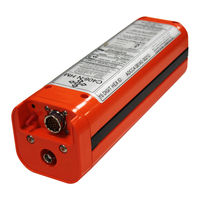
EMERGENCY LOCATOR TRANSMITTER
Brand:
COBHAM
| Category:
Transmitter
| Size: 1 MB
Table of Contents
Record of Revisions
3
Service Bulletin List
5
List of Effective Pages
7
Table of Contents
9
List of Figures
15
Introduction
17
Manual Usage
17
General
17
Application
17
Model Descriptions
19
C406-N
19
C406-N Hm
19
Figure 1. ELT Orthogonal Axes
19
Approvals
20
C406-N and C406-N HM
20
Battery
20
RTCA DO-160D Compliance
20
Table 1. Environmental Categories Breakdown
21
Frequency Allocations
22
Application
22
Discussion
22
List of Acronyms, Abbreviations, and Definitions
23
References
26
Regulatory Documents
26
Other Documents
27
Description and Operation
29
Description
29
Functional Overview
29
Components
30
Figure 2. C406-N Series ELT and Mounting Frame Assembly
30
Figure 3. Cockpit Remote Switch
31
Figure 4. Buzzer
31
Figure 5. Battery Pack Assembly
31
Figure 6. Rod and Whip Antennas
32
Figure 7. Blade Antennas
32
Operation
33
Operational Overview
33
Figure 8. ELT Operational Flow Diagram
33
Normal Operation
34
Manual Activation
34
ELT Reset
34
Functional Check
35
Specifications
36
Environmental and Physical
36
Table 2. Environmental and Physical Specifications
36
Electrical
37
Antennas
38
Table 4. Antenna Specifications
38
Test and Fault Isolation
39
Inspection and Test Regulatory Requirements
39
United States
39
Canada
39
Other Countries
40
Inspection and Test Procedures
41
Table 5. ELT Inspection and Test Checklist
41
Checklist
41
Preparation
42
Coax Cable and Wiring Connections Inspection - Item 1
42
ELT Mounting Tray and Hardware Inspection - Item 2
42
Battery Pack Inspection - Item 3
42
G-Switch Functional Check - Item 4
43
Performance Testing Setup
43
121.5 Mhz Frequency Measurement - Item 5A
44
Audio Modulation Check - Item 5B
44
Figure 9. Performance Tests Equipment Setup
44
121.5/243.0 Mhz Power Output Measurement - Item 5C
45
406 Mhz Frequency Measurement - Item 5D
45
406 Mhz Power Output Measurement - Item 5E
45
Current Draw Test - Item 5F
46
Figure 10. Current Draw Test Setup
46
Digital Message Verification - Item 5G
47
Figure 11. Long 406 Mhz Message Example
47
ELT Reset Check - Item 5H
48
Installed Transmitter Test - Item 6
48
Antenna Test - Item 7
49
Inspection and Test Documentation - Item 8
49
Fault Isolation
50
Table 6. ELT Self-Test Error Codes Troubleshooting Guide
50
Self-Test Error Troubleshooting Guidelines
50
ELT Troubleshooting Guidelines
52
Table 7. ELT Troubleshooting Guide
52
Removal
53
Elt
53
ELT Removal
53
Figure 12. ELT Removal Sequence
53
Battery
54
Battery Pack Removal
54
Figure 13. Battery Pack Removal
54
Material or Equipment Return
55
Shipment Information
55
Return Material Authorization
55
Regulatory Requirements and Guidelines
57
TSO C126, Paragraph D
57
Faa
57
Canada
57
Other Countries
58
Rtca
58
Mounting Tray
59
Location
59
Figure 14. C406-N Series ELT Outline and Dimensions
59
Installation
60
Figure 15. Typical Mounting Tray Installation
60
Antenna
62
Selection
62
Location
62
Installation
62
Figure 16. Rod Antenna 110-338 and Whip Antenna 110-343 Outlines and Dimensions
63
Figure 17. Blade Antennas 110-340 and 110-341 Outlines and Dimensions
64
Remote Switch
65
Location
65
Installation
65
Figure 18. Remote Switch Outline and Dimensions
65
Buzzer
66
Location
66
Installation
66
Figure 19. Buzzer Outline and Dimensions
66
Wiring
67
General Considerations and Recommendations
67
Remote Switch Harness Fabrication
67
Figure 20. Remote Switch Harness Arrangement
68
Figure 21. Remote Switch Harness Wiring Diagram
69
ELT 22-Pin Plug Installation
72
Figure 22. Harness ELT 22-Pin Plug Arrangement
72
Cockpit Remote Switch 9-Pin Plug Installation
73
Wiring Installation
73
Antenna Connection
74
Cockpit Remote Switch Power Connection
74
ELT Power Connection
74
Airframe Ground Connections
74
Buzzer Connection
74
Remote Switch Final Installation
75
ELT Installation and Test
76
Installation
76
Figure 23. ELT Installation Sequence
76
Post-Installation Testing
77
Installation Documentation
77
Battery Pack Installation
78
Battery Reinstallation
78
Figure 24. Battery Pack Installation
78
Figure 25. Battery Pack Screw Tightening Pattern
79
New Battery Installation
80
Helicopter Installations - Special Considerations
81
Background
81
Recommendations
81
Figure 26. ELT Orthogonal Axes
81
Orientation
82
Figure 27. Orientation of ELT for Helicopter Installations
82
Appendix A - Elt Registration
83
Background Information
83
Hex ID Code
83
Reason for Registration
83
Registration Information Resources
83
Registration
84
Responsibility
84
Required Information
84
Where to Register
84
Appendix B - Programming Adapter Option
85
Description and Operation
85
Purpose
85
Physical Description
85
Figure 28. Programming Adapter
85
PA Programming
86
Operation
86
Installation and Test
87
Wiring
87
Figure 29. Programming Adapter Interface Wiring Diagram
87
Assembly
88
Installation
89
Aircraft ID Verification Test
89
Figure 30. Programming Adapter Installation
89
Appendix C - Remote Switch Control Panel Option
91
Description and Operation
91
Purpose
91
Control Panel Description
91
Figure 31. Remote Switch Control Panel Assembly
91
Task
91
Subtask
91
Modified Buzzer Description
92
Operation
92
Remote Switch Control Panel Installation
93
Location
93
Installation
93
Figure 32. Cockpit Remote Switch Panel Outline and Dimensions
93
Elt
93
Modified Buzzer Installation
94
Location
94
Installation
94
Figure 33. Modified Buzzer Outline and Dimensions
94
Red
94
Yellow
94
Black
94
Wiring and Test
95
Remote Switch Control Panel Wiring Fabrication
95
Figure 34. Remote Switch Control Panel Wiring Diagram (130-4005 Modified Buzzer)
96
Modified Buzzer Wiring Fabrication
97
Remote Switch Control Panel Wiring Installation
97
Modified Buzzer Wiring Installation
98
Standard Buzzer Installation
98
Remote Switch Control Panel Final Installation
98
Figure 35. Remote Switch Control Panel Wiring Diagram (130-4004 Buzzer)
99
Remote Switch Control Panel Functional Test
100
Illustrated Parts List
101
Introduction
101
Purpose
101
IPL Usage Guide
101
Manufacturer Name and Address
102
Ordering Information
102
Explanation of Detailed Parts List Entries
103
Fig # & Item Column
103
Part # Column
103
Nomenclature Column
103
UPA (Units Per Assembly) Column
104
Detailed Parts List
105
Figure 36. C406-N Series ELT Main Assembly and Installation
105
Figure 37. Electrical Components
107
Figure 38. Antennas
109
Advertisement
Advertisement
Related Products
COBHAM C406-N Series
COBHAM C406-2 SERIES
COBHAM C-5000D P-25
COBHAM C-5000
COBHAM CH150-14
COBHAM FliteLine CVC-151
COBHAM H264ENC
COBHAM domo SOL4MTX Bodywire
COBHAM H264ENGTX
COBHAM H264TX
COBHAM Categories
Antenna
Marine Equipment
Radio
Touch terminals
Receiver
More COBHAM Manuals
Login
Sign In
OR
Sign in with Facebook
Sign in with Google
Upload manual
Upload from disk
Upload from URL