Table of Contents
Advertisement
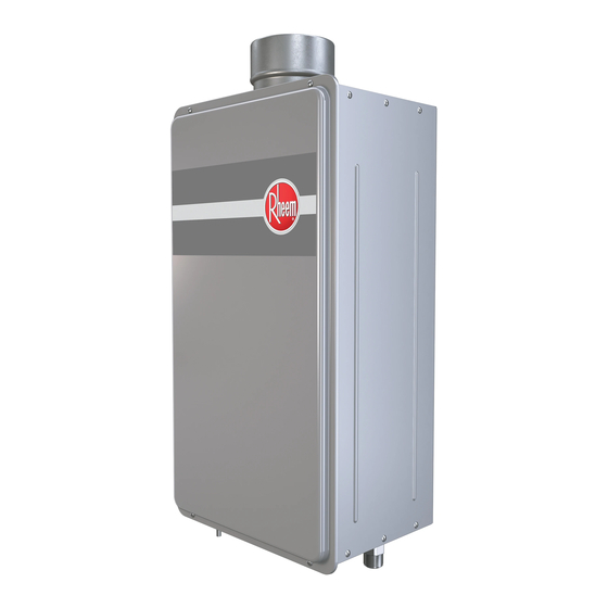
Direct Vent Gas
Tankless Water Heater
Rheem/ Ecosense
RTG-95DV (N,P)
ECO200DV (N,P) 3
RTG-84DV(N,P)
ECO180DV(N,P)3
RTG-64DV(N,P)
ECO150DV(N,P)3
Paloma/Wai Wela
PH2-28RDVS (N,P)
PH2-25RDVS (N,P)
PH2-20RDVS (N,P)
Ruud
RUTG-95DV (N,P)
RUTG-84DV (N,P)
RUTG-64DV (N,P)
Richmond
RMTG 95DV (N,P)
RMTG 84DV (N,P)
RMTG 64DV (N,P)
WARNING: If the information in these instructions is not followed exactly,
!
a fire or explosion may result, causing property damage, personal injury or death.
FOR YOUR SAFETY!
!
— Do not store or use gasoline or other
flammable vapors or liquids or other
combustible materials in the vicinity of
this or any other appliance. To do so may
result in an explosion or fire.
— WHAT TO DO IF YOU SMELL GAS
Do not try to light any appliance.
G
Do not touch any electrical switch;; do not
G
use any phone in your building.
Immediately call your gas supplier
G
from a neighbor's phone. Follow the
gas supplier's instructions.
AP15317 (10_09) DV Gas Manual 10 30 09.indd 1
Use & Care Manual
With Installation Instructions for the Installer
The purpose of this manual is twofold: one, to provide the installer with
the basic directions and recommendations for the proper installation
and adjustment of the water heater;; and two, to the owner–operator,
to explain the features, operation, safety precautions, maintenance and
troubleshooting of the water heater. This manual also includes a parts
list.
It is very important that all persons who are expected to install, operate
or adjust this water heater read the instructions carefully so they may
understand how to perform these operations. If you don't understand
these instructions or any terms within it, seek professional advice.
Any q uestions r egarding t he o peration, m aintenance, s ervice o r w arranty
of this water heater should be directed to the seller from whom it was
purchased. If additional information is required, refer to the section on
If You Need Service.
Do not destroy this manual. Please read carefully and keep in a safe
place for future reference.
!
Rheem/Ruud
GT-200 DV (N,P)
GT-180 DV (N,P)
!
CERTIFIED
R
Warning: This water heater is not suitable
!
for use in manufactured (mobile) homes!
Recognize this symbol as an indication of Important Safety
Information!
California Proposition 65 Warning: This product contains
chemicals known to the State of California to cause cancer, birth
defects or other reproductive harm.
If you cannot reach your gas supplier, call
G
the fire department.
Do not return to your home until authorized
G
by the gas supplier or fire department.
— Improper installation, adjustment,
alteration, service or maintenance can cause
property damage, personal injury or death.
Refer to this manual. Installation and service
must be performed by a qualified installer,
service agency or the gas supplier.
®
31-93681-00
AP15317 (10/09)
11/9/2009 3:10:22 PM
Advertisement
Table of Contents

Subscribe to Our Youtube Channel
Related Manuals for Rheem AP15317


Summary of Contents for Rheem AP15317
- Page 1 any phone in your building. Immediately call your gas supplier from a neighbor’s phone. Follow the gas supplier’s instructions. 31-93681-00 CERTIFIED AP15317 (10/09) ® AP15317 (10_09) DV Gas Manual 10 30 09.indd 1 11/9/2009 3:10:22 PM...
-
Page 2: Table Of Contents
Adjustment .... 35 High A ltitude A djustment . . .35 AP15317 (10_09) DV Gas Manual 10 30 09.indd 2 11/9/2009 3:10:22 PM... - Page 3 Read and follow water heater warnings and instructions. If owners manual is missing, contact the retailer or manufacturer. AP15317 (10_09) DV Gas Manual 10 30 09.indd 3 11/9/2009 3:10:23 PM...
- Page 4 Temperatures 85°F(29°C) and up to 140°F (60°C) can be achieved with the Main (UMC-117) remote control. See page 34 & 35 for minimum and maximum temperature adjustment. AP15317 (10_09) DV Gas Manual 10 30 09.indd 4 11/9/2009 3:10:23 PM...
- Page 5 G It is recommended that more than one method, such as soapy solution, gas detectors, etc., be used to detect leaks in gas applications. AP15317 (10_09) DV Gas Manual 10 30 09.indd 5 11/9/2009 3:10:23 PM...
-
Page 6: Safety Precautions
G Be sure your appliance is properly installed in accordance with local codes and the provided installation instructions. READ A ND FOLLOW THIS SAFETY INFORMATION CAREFULLY. SAVE THESE INSTRUCTIONS AP15317 (10_09) DV Gas Manual 10 30 09.indd 6 11/9/2009 3:10:24 PM... -
Page 7: Location
Instruction/Warning Label, located on the front panel of the heater differ, install the water heater according to the clearances stated on the label. AP15317 (10_09) DV Gas Manual 10 30 09.indd 7 11/9/2009 3:10:24 PM... -
Page 8: Inspect Shipment
instructions. Printed in USA ® Tankless Unit Use & Care Manual Manual A ppliance Remote Control Cable Pressure Relief Valve Gas Shut-off Valve (some models only) AP15317 (10_09) DV Gas Manual 10 30 09.indd 8 11/9/2009 3:10:25 PM... -
Page 9: Venting
The water heater must be installed with a 3”/5” diameter UL approved Category III Concentric Stainless Steel appliance concentric vent pipe or Rheem approved concentric vent pipe. Venting DANGER: Failure to The installation of venting must comply ... - Page 10 capped to prevent exhaust gases and condensate from entering Condensate Drain Line the building. The cap is (to suitable drain) supplied on the water heater. AP15317 (10_09) DV Gas Manual 10 30 09.indd 10 11/9/2009 3:10:25 PM...
- Page 11 A minmum clearance value determined by testing in accordance with section 2.20, or;; b) A reference to the following footnote: "Clearance in accordance with local installtion codes and the require- ments of the gas supplier." AP15317 (10_09) DV Gas Manual 10 30 09.indd 11 11/9/2009 3:10:25 PM...
- Page 12 between vent terminations of 19 inches (48 cm) for two unit installation. Maintain a center-to-center distance between vent terminations of 21 inches (53 cm) for three or more unit installation. AP15317 (10_09) DV Gas Manual 10 30 09.indd 12 11/9/2009 3:10:25 PM...
- Page 13 (30 cm) Ceiling Board Inspection Inspection Access Panel #1 Access (optional) Panel #2 (optional) Example A : Typical Horizontal Termination w/ 1/4” per foot DOWNWARD Slope AP15317 (10_09) DV Gas Manual 10 30 09.indd 13 11/9/2009 3:10:26 PM...
-
Page 14: Vertical Vent Termination Location
To Drain: Dispose of condensate in accordance to Vertical Vent Installation Straight Vertical local codes with Horizontal offset Vent Installation Standard Vertical Vent Termination AP15317 (10_09) DV Gas Manual 10 30 09.indd 14 11/9/2009 3:10:26 PM... -
Page 15: Water Connections
to achieve maximum flow rate. made. consideration. Gravity water pressure is not recommended. G To maintain proper performance, ensure sufficient water supply pressure. The AP15317 (10_09) DV Gas Manual 10 30 09.indd 15 11/9/2009 3:10:26 PM... - Page 16 for space heating or non-potable water distribution. A ll water piping and components shall be suitable for potable water. AP15317 (10_09) DV Gas Manual 10 30 09.indd 16 11/9/2009 3:10:28 PM...
-
Page 17: Relief Valve
may be needed to ensure that the relief valve and discharge line. the valve probe is not directly in the flow path of the water. AP15317 (10_09) DV Gas Manual 10 30 09.indd 17 11/9/2009 3:10:28 PM... -
Page 18: Gas Supply
NOTICE: For installations above 3,280 feet (1,000 m) elevation, contact a quaili- fied service technician to make the proper altitude adjustment. See page 35 for ad- ditional information. AP15317 (10_09) DV Gas Manual 10 30 09.indd 18 11/9/2009 3:10:29 PM... -
Page 19: Remote Control
BATH 2 tures up to 185° F (85° C). Qualified Technician 85°F (29°C) A djustment MIC-6 Manifold Optional (Sold MIC-180 or System Separately) MIC-185 Manifold System AP15317 (10_09) DV Gas Manual 10 30 09.indd 19 11/9/2009 3:10:29 PM... - Page 20 Gas Inlet Connection Cover Valve Remote Control Connection Terminals Projections Remote Control Cable Remote Remote Control Wall Control Cable Penetration Suitable Wall Anchors Control Base Plate Screw Screws AP15317 (10_09) DV Gas Manual 10 30 09.indd 20 11/9/2009 3:10:30 PM...
-
Page 21: Electrical Connection
<<BATH>> WATER FLOW SENSOR OVER HEAT LIMITER MODEL ONLY (UMC-117) (USC1-117) (USC2-117) CAPTEUR DE DÉBIT LIMITEUR DE SURCHAUFFE POUR MODÈLE INTÉRIEUR À 31-93618 0 D'EAU ÉVENT DIRECT SEULEMENT AP15317 (10_09) DV Gas Manual 10 30 09.indd 21 11/9/2009 3:10:30 PM... -
Page 22: Typical Installation
NOTICE: The National Fuel Gas Code (NFGC) and B149 mandates a manual gas shut-off valve: See NFGC/B149 for complete instructions. Local codes or plumbing authority requirements may vary from the instructions or diagrams provided and take precedent over these instructions. AP15317 (10_09) DV Gas Manual 10 30 09.indd 22 11/9/2009 3:10:30 PM... -
Page 23: Pipe Insulation
Don’t use pipe dope on water line with the guidelines found in the Use & connections and fittings. Care Manual and National Fuel Gas Code (CSA B149 in Canada). AP15317 (10_09) DV Gas Manual 10 30 09.indd 23 11/9/2009 3:10:31 PM... -
Page 24: Installation Checklist
Gas supply pressure is sufficient for the water heater. Supply cord and/or wiring meets all local codes. Gas line equipped with shut-off valve, union and sediment trap. AP15317 (10_09) DV Gas Manual 10 30 09.indd 24 11/9/2009 3:10:31 PM... -
Page 25: For Your Safety Read Before Operating
1.Turn off all electric power to the appliance if service is to be performed. 2.Turn the Gas Shutoff Valve located on the outside of the unit clockwise to the "OFF" position. AP15317 (10_09) DV Gas Manual 10 30 09.indd 25 11/9/2009 3:10:31 PM... -
Page 26: Water Temperature
145°F (63°C) Less than 3 seconds 150°F (66°C) About 1 seconds 155°F (68°C) About 1 second Table courtesy of Shriners Burn Institute AP15317 (10_09) DV Gas Manual 10 30 09.indd 26 11/9/2009 3:10:31 PM... - Page 27 Temperatures 85°F (29°C) and up to 140°F (60°C) can be achieved with the MAIN (UMC-117) remote control. See page 34 and 35 for maximum and minimum temperature adjustment. AP15317 (10_09) DV Gas Manual 10 30 09.indd 27 11/9/2009 3:10:31 PM...
-
Page 28: Care And Cleaning
The water filters should be cleaned on a G Turn the electrical power supply and monthly basis. cold water supply ON to the water heater. AP15317 (10_09) DV Gas Manual 10 30 09.indd 28 11/9/2009 3:10:31 PM... -
Page 29: Vent Inspection
codes and regulations. operate without the trap and the condensate is draining properly. condensate trap connected to the drain fitting and routed to the proper drain. AP15317 (10_09) DV Gas Manual 10 30 09.indd 29 11/9/2009 3:10:32 PM... -
Page 30: Draining
of approximately 1/8” (.32 cm) is This device only protects the internal flowing. Be sure to check the flow components of the water heater. It does NOT periodically. AP15317 (10_09) DV Gas Manual 10 30 09.indd 30 11/9/2009 3:10:33 PM... -
Page 31: Troubleshooting Tips
CAUTION: For your safety, DO NOT attempt repair of electrical wiring, gas piping, remote control, burners, vent connectors or other safety devices. Refer repairs to qualified service personnel. AP15317 (10_09) DV Gas Manual 10 30 09.indd 31 11/9/2009 3:10:33 PM... - Page 32 CAUTION: For your safety, DO NOT attempt repair of gas piping, remote control, burners, vent connectors or other safety devices. Refer repairs to qualified service personnel. AP15317 (10_09) DV Gas Manual 10 30 09.indd 32 11/9/2009 3:10:33 PM...
- Page 33 Heat Exchanger A ssy. Electrode Bypass Pipe Ignitor Blower Motor Gas Valve A ssy. Circuit Board Gas Supply. Hot Water Outlet Cold Water Supply Drain Plug Water Flow Solenoid AP15317 (10_09) DV Gas Manual 10 30 09.indd 33 11/9/2009 3:10:38 PM...
-
Page 34: Maximum Temperature
38 39 40 41 42 43 44 46 47 48 49* °C 52 54 60 AP15317 (10_09) DV Gas Manual 10 30 09.indd 34 11/9/2009 3:10:38 PM... -
Page 35: High A Ltitude A Djustment
As set from factory Dip switch adjustment Dip switch adjustment 3,280 feet (1,000m) 6,560 feet (2,000m) thru thru 6,560 feet (2,000m) 9,840 feet (3,000m) Location of DIP Switches on PC Board. AP15317 (10_09) DV Gas Manual 10 30 09.indd 35 11/9/2009 3:10:39 PM... -
Page 36: If Y Ou Need Service
and/or all venting design instructions shall remain with the appliance or with the exhaust vent terminal for the horizontally vented gas fueled heating appliance equipment at the completion of the installation. AP15317 (10_09) DV Gas Manual 10 30 09.indd 36 11/9/2009 3:10:39 PM...
Need help?
Do you have a question about the AP15317 and is the answer not in the manual?
Questions and answers