Sign In
Upload
Download
Table of Contents
Contents
Add to my manuals
Delete from my manuals
Share
URL of this page:
HTML Link:
Bookmark this page
Add
Manual will be automatically added to "My Manuals"
Print this page
×
Bookmark added
×
Added to my manuals
Manuals
Brands
Hoshizaki Manuals
Ice Maker
KM-1301SAH
Instruction manual
Hoshizaki KM-1301SAH Instruction Manual
Stackable crescent cuber
Hide thumbs
Also See for KM-1301SAH
:
Service manual
(84 pages)
,
Service manual
(113 pages)
1
2
Table Of Contents
3
4
5
6
7
8
9
10
11
12
13
14
15
16
17
18
19
20
21
22
23
24
25
26
27
28
29
30
31
32
33
34
page
of
34
Go
/
34
Contents
Table of Contents
Bookmarks
Table of Contents
Table of Contents
Specifications
Nameplate Rating
KM-1301SAH (Air-Cooled)
KM-1301SAH3 (Air-Cooled)
KM-1301SWH (Water-Cooled)
KM-1301SWH3 (Water-Cooled)
KM-1301SRH (Remote Air-Cooled)
KM-1301SRH3 (Remote Air-Cooled)
Dimensions/Connections
Km-1301Sah/3
Km-1301Swh/3
Km-1301Srh/3
Installation and Operating Instructions
Checks before Installation
How to Remove Panels
Location
Setup
Installation of Second Unit
Electrical Connection
Installation of Remote Condenser Unit
Checks before Installation
Location
Setup
Line Set
Electrical Connection
Stacking Remote Condenser Unit
Water Supply and Drain Connections
Water Supply
Final Checklist
Startup
Cleaning and Maintenance
Cleaning and Sanitizing Instructions
Cleaning Procedure
Sanitizing Procedure - Following Cleaning Procedure
Maintenance Instructions
Preparing the Icemaker for Long Storage
Advertisement
Quick Links
1
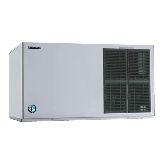
Km-1301Sah (Air-Cooled)
2
Km-1301Srh (Remote Air-Cooled)
3
Installation and Operating Instructions
4
Water Supply and Drain Connections
5
Cleaning and Maintenance
6
Cleaning and Sanitizing Instructions
7
Maintenance Instructions
Download this manual
See also:
Service Manual
Hoshizaki
Hoshizaki America, Inc.
"A Superior Degree
of Reliability"
www.hoshizaki.com
Stackable Crescent Cuber
Models
KM-1301SAH/3
KM-1301SWH/3
KM-1301SRH/3
INSTRUCTION MANUAL
Issued: 9-4-2008
Revised: 2-5-2013
Table of
Contents
Previous
Page
Next
Page
1
2
3
4
5
Advertisement
Table of Contents
Need help?
Do you have a question about the KM-1301SAH and is the answer not in the manual?
Ask a question
Questions and answers
Related Manuals for Hoshizaki KM-1301SAH
Ice Maker Hoshizaki KM-1301SAH/3 Service Manual
Stackable crescent cuber (113 pages)
Ice Maker Hoshizaki KM-1301SAH/3 Service Manual
Stackable crescent cuber (84 pages)
Ice Maker Hoshizaki KM-1301SWH/3 Instruction Manual
Stackable crescent cuber (46 pages)
Ice Maker Hoshizaki KM-1301SRH/3 Manual
(2 pages)
Ice Maker Hoshizaki KM-1301SAH-E Instruction Manual
Crescent cuber (31 pages)
Ice Maker Hoshizaki STACKABLE CRESCENT CUBER KM-1301SAH-E Service Manual
Stackable crescent cuber (59 pages)
Ice Maker Hoshizaki KM-0000SAE50 Service Manual
Km series crescent cuber (358 pages)
Ice Maker Hoshizaki KM-1301SAH-E Installation Manual
Stackable crescent cuber (50 pages)
Ice Maker Hoshizaki KM-1301SRH Instruction Manual
Stackable crescent cuber (34 pages)
Ice Maker Hoshizaki KM-1301S J-E Series Installation Manual
Stackable crescent cuber (101 pages)
Ice Maker Hoshizaki KM-1301SAJ-E Service Manual
Modular crescent cuber (46 pages)
Ice Maker Hoshizaki KM-1301SWJ/3 Service Manual
Modular crescent cuber (84 pages)
Ice Maker Hoshizaki KM-1301SRJZ/3 Instruction Manual
Stackable crescent cuber (45 pages)
Ice Maker Hoshizaki KM-1301SAJ/3 Service Manual
Modular crescent cuber (85 pages)
Ice Maker Hoshizaki KM-1301SAJ Instruction Manual
Stackable crescent cuber (45 pages)
Ice Maker Hoshizaki KM-1301SRJ Instruction Manual
Stackable crescent cuber (45 pages)
This manual is also suitable for:
Km-1301sah/3
Km-1301swh
Km-1301swh/3
Km-1301srh
Km-1301srh/3
Table of Contents
Save PDF
Print
Rename the bookmark
Delete bookmark?
Delete from my manuals?
Login
Sign In
OR
Sign in with Facebook
Sign in with Google
Upload manual
Upload from disk
Upload from URL


Need help?
Do you have a question about the KM-1301SAH and is the answer not in the manual?
Questions and answers