Generac Power Systems 6294 Installation And Operating Instructions Manual
Transfer switch
Hide thumbs
Also See for 6294:
- Installation and operating instructions (5 pages) ,
- Specifications (2 pages) ,
- Installation and operating instructions manual (25 pages)
Table of Contents
Advertisement
Available languages
Available languages
Installation and Operating Instructions
MANUAL TRANSFER SWITCH - MODELS 6294, 6408 and 6376
WARNING: Generac
®
transfer switches should be installed by a professional electrician familiar with electrical wiring and codes, and experienced in working with generators.
Generac accepts no responsibility for accidents, damages or personal injury caused by incorrect installation. This transfer switch is intended for surface mounting INDOORS only.
Our transfer switches are UL listed to UL 1008 and meet the criteria of National Electrical code Article 702.6 for Optional Standby Systems. CAUTION: If using the generator and
transfer switch for larger appliances, such as electric water heaters, clothes dryers, electric ranges and small air conditioners, check the labels on the appliances to be sure they do
NOT exceed the rating of the generator. No appliance should have an amperage rating that exceeds the individual breaker rating in the transfer switch (20 or 30 amps).
CALIFORNIA PROPOSITION 65 WARNING: Engine exhaust and some of its constituents are known to the State of California to cause cancer, birth defects and other reproductive
harm. This product may contain or emit chemicals known to cause cancer, birth defects and other reproductive harm.
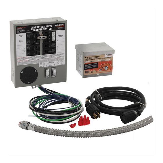
MODEL 6294 KIT SHOWN
What is Included in this Carton:
•
Manual Transfer Switch with wire harness, conduit, fittings and wire connectors (6)
•
30 Amp Power Inlet Box (Models 6294 and 6408 only)
•
10 Foot Power Cord with L14-30 male and female ends (Models 6294 and 6408 only)
•
L14-20 male plug (Model 6408 only)
•
Installation Manual and Warranty Registration card
Tools and Items Needed for Installation:
•
¼" nut driver, 2-1/8" hole saw (if flush mounting)
•
Screwdrivers, straight blade and Phillips
•
Electric drill, drill bits, wallboard saw
•
Wire cutter/stripper
•
Safety eye goggles
•
Anchors and screws to mount transfer switch to wall
•
New 60A 2-pole, 240V circuit breaker to install in main load center – should be same manufacturer as existing load center.
•
10 gauge 4-wire building wire and conduit to connect between power inlet box and transfer switch
Optional Items for Installation:
Arc-fault, GFCI or Surge protection circuit breakers. If Arc-fault, GFCI or Surge protection circuit breakers are used as the branch circuit protector in the main load
•
center, they MUST be used in the manual transfer switch. You may be able to re-use your existing AFCI, GFCI and Surge protection circuit breakers in the manual
transfer switch. See list of compatible breakers below.
Wire, fittings and conduit to connect the Power Inlet Box to the transfer switch
•
White, green, black and red THHN or MTW wire, 10 AWG, 300V rated
•
Switched Neutral Kit (SNK). If your portable generator has the neutral bonded to the frame of the generator AND 240V "full-power" receptacle is GFCI protected, you
•
will need to install a SNK accessory with your transfer switch to avoid nuisance tripping of the GFCI breaker on the generator.
NOTE ON NEUTRAL BONDED GENERATORS: Some portable generators are intended for use on jobsites, and therefore are subject to OSHA regulations for GFCI protection on all receptacles.
These "contractor grade" generators have their neutral wire bonded to the ground wire to pass OSHA inspection on job sites, and when connected to a transfer switch, this may cause nuisance
tripping of the generator GFCI breaker. If you're using a neutral bonded generator to power a house or building through a transfer switch, then determine if the neutral bond wire on the
generator can be disabled without voiding the warranty, preferably by a dealer or a qualified electrician. NOTE: After this action, the generator will no longer pass OSHA inspection on job sites.
Consult the manufacturer of your generator to determine if the neutral bond can be removed. If it can be disabled, then no modifications to your transfer switch installation are needed. If the
neutral bond cannot be disabled or voids the generator warranty, you must install a Switched Neutral Kit (SNK) accessory with your transfer switch.
Compatible Circuit Breakers:
•
Siemens/Murray QT, QPH, HQP, QPF (GFCI), QPHF, QFP, QE, QEH, QAF (Arc Fault), QP (Surge Protector)
•
Cutler-Hammer Series BD, BR, BQ, GFC
•
Challenger Type A, C, HAGF
•
Square D Series HOM (Homeline)
•
GE Series THQL
Thank you for purchasing a Generac Transfer Switch to safely connect a portable
generator to the load center in your home or business (single phase only) for
standby power applications. Product features include:
Generator and Utility feeds mechanically interlocked to prevent dangerous utility or
•
generator back feeding – thereby avoiding property damage and serious injury to
electrical workers.
Pre-wired for fast, easy connection to the load center.
•
Each model can be expanded to up to 10 circuits using standard interchangeable type
•
circuit breakers. See Step 2, Section III.
Accommodates GFCI and Arc-Fault breakers to meet the latest NEC requirements.
•
Dual wattmeters help you monitor and balance the loads on your generator, prolonging
•
generator life.
Safe generator connection – Install the Power Inlet Box in a convenience location
•
outside for a quick cord connection to your generator.
Surface Mount enclosure indoors. Not approved for outdoor installation.
•
1
Advertisement
Table of Contents

Related Manuals for Generac Power Systems 6294


Summary of Contents for Generac Power Systems 6294
-
Page 1: Compatible Circuit Breakers
Generac accepts no responsibility for accidents, damages or personal injury caused by incorrect installation. This transfer switch is intended for surface mounting INDOORS only. -
Page 2: Step 1: Planning Your Installation
TABLE 1 - SPECIFICATIONS Model: 6294, 6408, 6376 # Circuits Provided on Transfer Switch Max # Circuits REQUIRED BREAKER FOR MAIN LOAD CENTER 60 amp 2-pole (not included) Utility Main Breaker 60 amp 2-pole Generator Main Breaker 30 amp 2-pole Breakers Provided with Unit 2 –... -
Page 3: Step 2: Installation Procedure
If additional circuit(s) are added, the installer is responsible for providing appropriately sized wire(s) for each circuit. III. INSTALLING THE POWER INLET BOX (Models 6294 and 6408 Only) Remove the front cover of the Power inlet box. Remove the 3 screws that secure the flanged inlet to the bottom plate. -
Page 4: Step 3: Using Your Transfer Switch
Protected by US Patent No. US 6,861,596 B2 Generac Power Systems, Inc. Toll Free: 1-888-GENERAC www.generac.com 0196990SBY © 2012 Generac Power Systems, Inc. All Rights Reserved. GenTran and Generac are registered trademarks of Generac Power Systems, Inc. PN 500507 Rev B... - Page 5 être installés par un électricien professionnel qui se connaît bien en câbles et codes électriques et a de l'expérience avec les génératrices. Generac décline toute responsabilité pour les accidents, les dommages ou les blessures causés par une installation incorrecte. Ce commutateur de transfert sera monté...
-
Page 6: Étape 1 : Préparer L'installation
Série Square D HOM (Homeline) • Série THQL de GE TABLEAU 1 - CARACTÉRISTIQUES Modèle : 6294 – 6408 – 6376 Nombre de circuits disponibles sur le commutateur de transfert Nombre maximum de circuits DISJONCTEUR OBLIGATOIRE POUR LE CENTRE DE Bipolaire de 60 ampères... -
Page 7: Étape 2 : Procédure D'installation
FIGURE 1: INSTALLATION HABITUELLE : TABLEAU 2 - FEUILLE DE TRAVAIL DU CIRCUIT Circuit 6294, 6408, 6376 Appareil(s) ÉTAPE 2 : PROCÉDURE D'INSTALLATION : VEUILLEZ LIRE CE MANUEL EN TOTALITÉ AVANT D'ESSAYER DE DÉBALLER, ASSEMBLER, INSTALLER, UTILISER OU ENTRETENIR CET APPAREILLAGE. LES BOÎTIERS DU COMMUTATEUR DE TRANSFERT CONTIENNENT DES TENSIONS DANGEREUSES QUI PEUVENT CAUSER LA MORT OU DES BLESSURES GRAVES. -
Page 8: Étape 3 : Utilisation Du Commutateur De Transfert
III. INSTALLATION DE LA BOÎTE D'ENTRÉE D'ALIMENTATION (Modèles 6294 et 6408) Enlevez la couverture de la boîte d'entrée d'alimentation. Enlevez les 3 vis fixant l'entrée à bride sur la plaque inférieure. - Page 9 Protégé par brevet américain No. US 6,861,596 B2 Generac Power Systems, Inc. Numéro gratuit : 1-888-GENERAC www.generac.com © Generac 2012 Power Systems, Inc. Tous droits réservés. GenTran et Generac sont des marques déposées de Generac Power Systems, Inc. 500507 Rév. A...
- Page 10 Generac no se responsabiliza por accidentes, daños o lesiones personales causados por una instalación incorrecta. Este interruptor de transferencia está diseñado para montaje en superficies sólo EN INTERIORES.
-
Page 11: Paso 1: Planificación De La Instalación
Square Serie D HOM (Homeline) • GE Serie THQL TABLA 1: ESPECIFICACIONES Modelo: 6294 – 6408 - 6376 N.º de circuitos proporcionados en el interruptor de transferencia N.º máximo de circuitos DISYUNTOR REQUERIDO PARA EL CENTRO DE CARGA PRINCIPAL de 60 amperios, 2 polos (no se incluye) Disyuntor principal del servicio eléctrico... -
Page 12: Paso 2: Procedimiento De Instalación
III. INSTALACIÓN DE LA CAJA DE ENTRADA DE ALIMENTACIÓN ELÉCTRICA (incluyendo en 6294 y 6408) Quite la tapa delantera de la caja de alimentación eléctrica. Quite los 3 tornillos que sujetan la entrada bridada a la placa inferior. - Page 13 Protegido por patente estadounidense N.º US 6,861,596 B2 Generac Power Systems, Inc. Sin cargo: 1-888-GENERAC www.generac.com © 2012 Generac Power Systems, Inc. Todos los derechos reservados. GenTran y Generac son marcas registradas de Generac Power Systems, Inc. PN 500507 Rev. A...
Need help?
Do you have a question about the 6294 and is the answer not in the manual?
Questions and answers