
Related Manuals for Pressure Systems 98RK-1


Summary of Contents for Pressure Systems 98RK-1
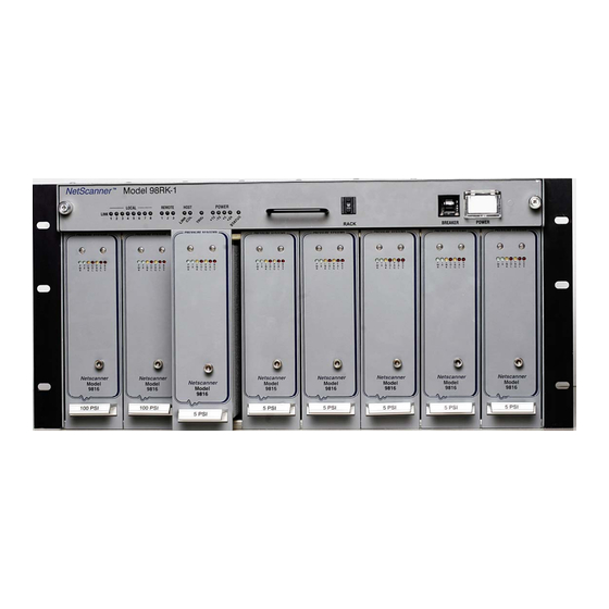
- Page 1 Model 98RK-1 & Model 9816 Rackmount Intelligent Pressure Scanner User’s Manual August 2009 NetScanner™ System www.PressureSystems.com...
- Page 2 © This User’s Manual is a copyright product of Pressure Systems, Inc., 2009 Permission is hereby granted to make copies and distribute verbatim copies of this manual, provided the copyright notice and this permission notice are preserved on all copies.
-
Page 3: General Information
Introduction This User’s Manual will: Explain the electrical and pneumatic pressure connections for the Model 98RK-1 Scanner Interface Rack and Model 9816 Rackmount Intelligent Pressure Scanners. Provide computer set-up instructions to make a proper Ethernet connection on most ®... - Page 4 The NetScanner™ System is a comprehensive, distributed data acquisition system centered around PSI’s proven Intelligent Pressure Scanner technology. The rackmount configuration of this system is comprised of Model 98RK-1 Scanner Interface Racks, each housing up to eight (8) Model 9816 Rackmount Intelligent Pressure Scanners networked via the Ethernet interface.
-
Page 5: Description Of The Instruments
‘plug and play’ transducer replacement. Ease of calibration - 98RK-1 Scanner Interface Rack features pneumatic hook-ups on the back-panel and front-panel (if ordered) to ease scanner calibration. Each 9816 Intelligent Pressure Scanner module contains a pneumatic calibration manifold and software commands to automatically perform re-zero and span adjustment calibrations. -
Page 6: Pressure Ranges
Pressure Systems, Inc. 98RK-1 & 9816 User’s Manual© The 98RK-1 Scanner Interface Rack features a gigabit switch that significantly increases processing capabilities and speed. System calibration consists of zero and span calibration only at any given temperature. Full thermal re-calibration is never necessary. -
Page 7: Communication Interfaces
TCP/UDP/IP protocols. This interface provides high data transfer rates (10MBit/sec.) and system connectivity. The 98RK-1 incorporates a gigabit switch which auto negotiates the highest speed connection supported by the connected equipment. The 98RK-1 incorporates a universal input AC-DC power supply accepting input voltages from 90-250 VAC at 50 or 60 Hz and is capable of supporting a full complement of NetScanner products. -
Page 8: Safety Considerations
Each shipment will contain one or more of the following components: 98RK-1 Scanner Interface Rack chassis 9816 Intelligent Pressure Scanner modules (installed in the 98RK-1, if ordered) Start-up software (NUSS) on CD-ROM 9882 Pneumatic Blanking Unit (if purchased) ... -
Page 9: Connections And Setup
STEP 2 connector of the 9082 cable to your scanner’s connector port. Connect the other end of the same cable to one of the ports on the rear of the 98RK-1 chassis labeled “Remote NetScanner Module Interface.” (See Figure 2.1) Page 7 www.PressureSystems.com... - Page 10 Pressure Systems, Inc. 98RK-1 & 9816 User’s Manual© Figure 2.1 Typical Hook-up Arrangement Using the 98RK-1 Scanner Interface Rack Page 8 www.PressureSystems.com...
-
Page 11: Network Communications Hookup
2.3.3 Network Communications Hookup The 98RK-1 Scanner Interface Rack chassis has an Ethernet connector port on the rear of the unit through which all scanners in the rack may be connected to the network or the Ethernet card in your PC or work station. This port is labeled “ TO HOST” (using an RJ-45 connector). - Page 12 Pressure Systems, Inc. 98RK-1 & 9816 User’s Manual© ® Initial Network Screen for Windows With your mouse, right-click on the "Local Area Connection" icon. A drop-down menu STEP 7 will appear. Scroll down the menu and select (left-click) the "Properties" line.
- Page 13 Pressure Systems, Inc. 98RK-1 & 9816 User’s Manual© A screen example is shown here. With your mouse, right-click on the "Local Area Connection" icon. A drop-down menu STEP 9 will appear. Scroll down the menu and select (left-click) the "Properties" line.
- Page 14 Pressure Systems, Inc. 98RK-1 & 9816 User’s Manual© If the TCP/IP protocol is not found, it must be installed. To install, select "Install" as STEP 11 shown on the "General" tab on the "Local Area Connection Properties" screen. Page 12...
- Page 15 Pressure Systems, Inc. 98RK-1 & 9816 User’s Manual© Once the correct TCP/IP protocol is installed and verified for the proper Ethernet card, the IP address (under TCP/IP Properties), that is compatible with the pressure STEP 12 scanner(s), must be set.
- Page 16 Pressure Systems, Inc. 98RK-1 & 9816 User’s Manual© To set the PC address: Select "Use the following TCP/IP address." It is suggested that the IP Address read 200.xxx.yyy.zzz where xxx, yyy, and zzz are unique locations that do not match any other address on the network. (Check with your...
- Page 17 Pressure Systems, Inc. 98RK-1 & 9816 User’s Manual© Connect the Ethernet cable between the 98RK-1 “TO HOST” RJ-45 connector and STEP 14 the Ethernet card of your host computer. After you set the IP address and the subnet mask, click “OK”. You may then be prompted to re-start your computer so that the inputs will be recognized.
- Page 18 At this point, the best way to see if you have correctly connected your NetScanner System with the 98RK-1 Scanner Interface Rack is to observe the Host Link (LNK) light, located on the front panel of the 98RK-1. The 98RK-1 will auto-negotiate for maximum speed connections (up to 1 gigabit/sec) and will automatically correct for swapped signal pairs.
- Page 19 Pressure Systems, Inc. 98RK-1 & 9816 User’s Manual© NUSS Initial Screen Once NUSS is selected, the Network Status Screen (shown above) appears. Note that a "Querying Network" message briefly appears, and then the Nodes on Network box will automatically display the each NetScanner module hooked into the network. It also shows their serial number, IP address, and whether or not they are active (connected or disconnected).
- Page 20 Pressure Systems, Inc. 98RK-1 & 9816 User’s Manual© Connect to any module. (When a connection has been established, the top of the module icon will turn yellow.) STEP 18 Select (left click) the module's icon in the Node map. Right-click on the module's icon (in either the Node Map or the description box), and select (left click) on "Connect"...
-
Page 21: Pressure Connections
Additional control, purge, and calibration inputs are found on the rear of the 98RK-1. The function of each input port is clearly engraved or printed next to each input (see Figures 2.2, 2.3 and 2.3a, next page). Connections are through bulge tubing, compression fittings, or special user-supplied fittings on the tubing plate. - Page 22 Pressure Systems, Inc. 98RK-1 & 9816 User’s Manual© Figure 2.2 98RK-1 Rear View Figure 2.3 Figure 2.3a Expanded View of 98RK-1 Scanner Expanded View of Model 9816 Intelligent Interface Rack Rear Manifold Pressure Scanner Rear Manifold Page 20 www.PressureSystems.com...
- Page 23 2.3.4.1 Supply Air The 98RK-1 chassis requires an 80 psig minimum (125 psig maximum) dry air (or inert gas) supply which is used to shift the 9816 internal calibration valve (in each scanner) between its different positions. Each 98RK-1 contains a fitting marked “SUPPLY” for this input (see Figure 2.2, previous page).
- Page 24 2.3.4.3 CAL Mode Inputs The 9816 model (in the 98RK-1) contains pneumatic backplane inputs for CAL(CAL 1-8) and CAL REF. When the module’s internal calibration valve is placed in the CAL/RE-ZERO position, all DH200 transducer pressure inputs are pneumatically connected to the CAL input ports. All DH200 reference inputs are pneumatically connected to the CAL REF input port.
- Page 25 In the case of a 9816 with multiple pressure ranges installed, the unit will use the CAL range of the lowest installed full scale pressure range. CAL port assignments are based on a pressure range, NOT 98RK-1 Note slot assignments.
- Page 26 Pressure Systems, Inc. 98RK-1 & 9816 User’s Manual© 2.3.4.4 PURGE Mode Inputs 9816 scanners are supplied with a purge/leak-charge feature. The purge feature allows users to apply positive pressure to the PURGE input which will then be vented out of the user input ports, forcing contaminants (such as moisture) out of the pneumatic input lines.
- Page 27 Pressure Systems, Inc. 98RK-1 & 9816 User’s Manual© 2.3.4.5 LEAK Mode Inputs The purge/leak-charge valve design includes a leak check feature capable of testing the integrity of user pneumatic connections as well as those within the 9816 module. For the leak mode to be used, all RUN mode pressure inputs must be dead-ended (closed) by the user.
- Page 28 2.3.5 Cluster, Rack, and Slot Identification The 98RK-1 Scanner Interface Rack can operate as a single unit, with one (1) to eight (8) pressure scanners installed in each rack. Racks may also be grouped together as a cluster of racks as part of a larger data acquisition system.
- Page 29 The cluster address is set via a slotted screwdriver-adjustable hexadecimal switch on the PC- 293 (Ethernet Controller board), located in the pull-out slide tray (front panel of the 98RK-1). Cluster address settings are 0 through F (a total of 16). In the illustration, the hexadecimal switch is annotated.
- Page 30 The rack address is set via a 16-position (0 through 15) push wheel switch, located on the front panel of the 98RK-1. The slot addresses are numbered 1 through 8, starting from the leftmost slot in the 98RK-1 and each scanner’s address is fixed by its physical presence in the rack.
-
Page 31: Acquiring Data
Pressure Systems, Inc. 98RK-1 & 9816 User’s Manual© Acquiring Data From the Acquire menu, select “Acquire Data” to read the pressure of each channel STEP 20 on the screen. The pressure is displayed both in engineering units and on the individual bar graphs as a proportion of transducer full scale. -
Page 32: Tcp/Udp/Ip Protocols
System Intelligent Pressure Scanner modules (Model 9816) that are connected to the various slots of the 98RK-1 Scanner Interface Rack chassis, as well as the data or status responses returned by these modules. Some of the commands are similar to those for ™... - Page 33 Pressure Systems, Inc. 98RK-1 & 9816 User’s Manual© transmissions by sending commands to the modules, which are normally servers. However, a module can initiate its own transmissions in some operating modes (e.g., the hardware- triggered or free-run autonomous host streams generated by the Configure/Control Autonomous Host Streams ('c') command).
- Page 34 (in one more 4-bit hex digit in the bit map shown highlighted below). Bit 16 (Channel S) specifies the 98RK-1 rack’s source air transducer and Bit 17 (Channel P) specifies the purge transducer. Bits 18 and 19 will remain unused (must be=0) unless they become defined in a future software release.
- Page 35 Pressure Systems, Inc. 98RK-1 & 9816 User’s Manual© In the following example 20-bit (5-hex digit) position field, internal channels 16 and 1, and both external P & S pressures, are selected: Bit# Chan# Binary When all applicable internal channel bits are set in the position field (i.e., FFFF for a 16-channel 9816 module), it specifies all internal channels.
- Page 36 Pressure Systems, Inc. 98RK-1 & 9816 User’s Manual© 3.1.3.5 Format Field Some commands, that either send data to a module (as command parameters), or cause the host to receive data (via command’s response), have an extra format parameter (f digit) appended to (or specified in) the position field.
- Page 37 Pressure Systems, Inc. 98RK-1 & 9816 User’s Manual© The error response consists of the letter ‘N’ (for NAK, or negative acknowledge), followed by a 2-digit hexadecimal error code. The following table lists the error codes that can be returned ™...
-
Page 38: Functional Command Overview
™ In the NetScanner System (using the 98RK-1 Scanner Interface Rack), the Power-Up Clear ('A') command may be used as a simple command to elicit a known response from a module. Although this causes no internal function within the module, it will result in an acknowledgment being returned to the host computer to verify proper communications. - Page 39 Pressure Systems, Inc. 98RK-1 & 9816 User’s Manual© that a power reset has occurred in a module is to notice that the TCP/IP socket connection is no longer valid. At any point during module operation, the Reset ('B') command may be used to return any module to its default “reset”...
- Page 40 Pressure Systems, Inc. 98RK-1 & 9816 User’s Manual© 3.1.5.3 Calibration Adjustment of Offset/Gain Correction Coefficients ™ All NetScanner System Intelligent Pressure Scanners have built-in software commands (and pneumatic hardware) to perform a periodic zero and span calibration adjustment of its internal or attached pressure transducers.
- Page 41 Pressure Systems, Inc. 98RK-1 & 9816 User’s Manual© The above correction coefficients are maintained internally in IEEE floating-point format. The Read Internal Coefficients ('u') command and the Download Internal Coefficients ('v') command can return (or manually set) calibration coefficients to the host in decimal or hex dump formats in their responses.
- Page 42 Pressure Systems, Inc. 98RK-1 & 9816 User’s Manual© 3.1.5.6 Other Functions Some commands may be used at any time to obtain information about the internal setup and status of a module. The Read Module Status ('q') command is an example. Also, the Set Operating Options ('w') command, though generally used after power-up reset, may also be used at other times as well to change system operation.
-
Page 43: Detailed Command Description Reference
Pressure Systems, Inc. 98RK-1 & 9816 User’s Manual© Detailed Command Description Reference ™ All commands applicable to the Model 9816 NetScanner System models are described on the following pages and summarized in the following table. Table 3.1 ™ Model 9816 NetScanner... -
Page 44: Power Up Clear (Command 'A')
Pressure Systems, Inc. 98RK-1 & 9816 User’s Manual© POWER UP CLEAR (Command 'A') Purpose: This command has no internal module affect. It is used as a simple method to verify proper communications to the 9816 scanner. Command “A” ‘A’ is the command letter Response “A”... -
Page 45: Reset (Command 'B')
Pressure Systems, Inc. 98RK-1 & 9816 User’s Manual© RESET (Command 'B') Purpose: Instructs the module to reset internal operating parameters, and to set all internal control variables to their default “reset” state (see description below). The current TCP/IP socket connection will remain open. Execution after a power off/on cycle is optional (unnecessary). -
Page 46: Configure/Control Multi-Point Calibration (Command 'C')
Pressure Systems, Inc. 98RK-1 & 9816 User’s Manual© CONFIGURE/CONTROL MULTI-POINT CALIBRATION (Command 'C') Purpose: This command is actually four (4) sub-commands. The first configures and starts a Multi-Point Calibration adjustment function for selected channels in the module. Another is repeated multiple times to collect data for each defined calibration point. - Page 47 Pressure Systems, Inc. 98RK-1 & 9816 User’s Manual© Command 'C'— Sub-command Index 00: Configure & Start Multi-Point Calibration This sub-command has four (4) additional required parameters used to configure and start the Multi-Point Calibration function. “C 00 pppp npts ord avg”...
- Page 48 Pressure Systems, Inc. 98RK-1 & 9816 User’s Manual© Example: ● Configure and start the Multi-Point Calibration function so that it affects only the first four (4) channels of the module. Three (3) pressure calibration points will by supplied when we continue this function later (see example for ‘01’ sub-command below). A linear (1st order) fit will be used to obtain a new set of offset and gain correction coefficients for these four (4) channels.
- Page 49 Pressure Systems, Inc. 98RK-1 & 9816 User’s Manual© Command 'C'— Sub-command Index 01: Collect Data for a Calibration Point This sub-command has two (2) additional required parameters. “C 01 pnt pppp.pppp” Command ‘C’ is the command letter. ‘ 01’ is the sub-command index (ii) for Collect Data ‘...
- Page 50 Pressure Systems, Inc. 98RK-1 & 9816 User’s Manual© Example: ● Supply each of the previously-specified three (3) pressure calibration points to the Multi- Point Calibration function, as was stated in the previous example of the Configure and Start (‘00’) sub-command. Assume that all the affected four (4) channels have differential transducers with the same -5 to +5 psi range.
- Page 51 Pressure Systems, Inc. 98RK-1 & 9816 User’s Manual© Command 'C'- Sub-command Index 02: Calculate & Apply Correction Coefficients This sub-command has no additional parameters. “ C 02” Command ‘C’ is the command letter. ‘ 02’ is the sub-command index (ii) for Calculate & Apply NOTE: all parameters are separated by a space.
- Page 52 Pressure Systems, Inc. 98RK-1 & 9816 User’s Manual© Example: ● Finish the Multi-Point Calibration function previously started (as indicated by the previous examples of 'C' sub-commands ‘00’ and ‘01’). Calculate new adjustment coefficients, and save them in the non-volatile memory of the module’s transducers.
- Page 53 Pressure Systems, Inc. 98RK-1 & 9816 User’s Manual© Command 'C'— Sub-command Index 03: Abort Multi-Point Calibration This sub-command has no additional parameters. “C 03” Command ‘C’ is the command letter. ‘ 03’ is the sub-command index (ii) for Abort. NOTE: all parameters are separated by a space.
- Page 54 Pressure Systems, Inc. 98RK-1 & 9816 User’s Manual© READ TRANSDUCER VOLTAGES (Command 'V') Purpose: Returns, for the specified channels, the most recently acquired raw pressure data, converted to volts directly from the averaged A/D counts. This simple engineering-unit conversion bypasses any usage of the transducer’s factory- calculated coefficients or the final calibration process’s correction coefficients...
- Page 55 Pressure Systems, Inc. 98RK-1 & 9816 User’s Manual© Example: ● Send TCP/IP command to 9816 module (via its connected socket) that returns decimal voltage data for internal channels 1, 5, 9, and 13: “V11110” Response contains data for channels 13, 9, 5, and 1 (left to right): “...
-
Page 56: Calculate And Set Gains (Command 'Z')
(f=0). NOTE: This command may only be applied to the sixteen (16) internal channels. It is not applicable for the external 98RK-1’s purge/supply (P & S) channels. Normally this command requires that the exact full scale input pressure be applied to the affected channels. - Page 57 Pressure Systems, Inc. 98RK-1 & 9816 User’s Manual© The calculated gain values from the latest 'Z' command will be Note lost when the module is powered OFF. To save these gain terms to each transducer's nonvolatile memory, refer to the Set Operating Options ('w') command (index 09).
-
Page 58: Read Transducer A/D Counts (Command 'A')
Pressure Systems, Inc. 98RK-1 & 9816 User’s Manual© READ TRANSDUCER A/D COUNTS (Command 'a') Purpose: Returns the most recently acquired raw pressure data for the specified channels in averaged signed A/D counts (in the range -32768 to +32767). This simple data bypasses any usage of the transducer’s factory-calculated coefficients or... - Page 59 Pressure Systems, Inc. 98RK-1 & 9816 User’s Manual© Example: Send TCP/IP command to 9816 module (via its connected socket) that returns decimal ● raw “pressure” A/D counts data for internal channels 1, 5, 9, and 13: “a11110” Response contains data for channels 13, 9, 5, and 1 (left to right): "32767.000000 -32700.000000 10.000000 16385.000000"...
-
Page 60: Read High-Speed Data (Command 'B')
Pressure Systems, Inc. 98RK-1 & 9816 User’s Manual© READ HIGH-SPEED DATA (Command 'b') Purpose Returns the most recent scanned and averaged data from all channels of the module as fast as possible. Data is returned directly in its internal (IEEE single- precision float) binary form (as per implied format 7). -
Page 61: Define/Control Autonomous Host Streams (Command 'C')
Pressure Systems, Inc. 98RK-1 & 9816 User’s Manual© DEFINE/CONTROL AUTONOMOUS HOST STREAMS (Command 'c') Purpose: Defines and controls the autonomous delivery of any of up to three concurrent high-speed data streams to the host computer. Such data streams may be delivered “continuously”... - Page 62 Pressure Systems, Inc. 98RK-1 & 9816 User’s Manual© The maximum rate of any one stream’s delivery is practically limited to the maximum possible scan and data conversion rate of all the module’s channels. Normally, these programmable host streams deliver host data at rates equal to or slower than this natural cycle.
- Page 63 Pressure Systems, Inc. 98RK-1 & 9816 User’s Manual© Command 'c'— Sub-command Index 00: Configure a Host Delivery Stream This sub-command is used to configure the parameters of each of the three possible concurrent host delivery streams, one at a time. Following this configuration phase, the stream (1, 2, or 3) may be started and stopped with other sub-commands.
- Page 64 Pressure Systems, Inc. 98RK-1 & 9816 User’s Manual© internal channels. Following completion of the acquisition (and EU conversion) cycle, the module will also deliver the requested data channels to the host. In this manner, users are provided with highly synchronized data acquisition and delivery from one or more modules.
- Page 65 Pressure Systems, Inc. 98RK-1 & 9816 User’s Manual© NOTE: With the exception of binary format 7, all other formats include a leading space in each datum delivered in each stream packet. The number of stream packets (num) parameter is a positive integer count (specified with 1 to 5 numeric digits as needed).
- Page 66 Pressure Systems, Inc. 98RK-1 & 9816 User’s Manual© Command 'c'— Sub-command Index 01: Start Stream This sub-command is used to start the delivery of any previously configured host stream in a module. If the stream started is of “continuous” duration, then it will be necessary to use the Stop Stream sub-command later.
- Page 67 Pressure Systems, Inc. 98RK-1 & 9816 User’s Manual© For periodic hardware-triggered streams, that are never suspended and resumed after being initially enabled, the sequence number may also serve as a “relative” time stamp if the period (in milliseconds) of the hardware trigger is known.
- Page 68 Pressure Systems, Inc. 98RK-1 & 9816 User’s Manual© Command 'c'— Sub-command Index 02: Stop Stream This sub-command is used to abort (or temporarily suspend) the delivery of any previously started host stream in a module, one at a time or all together, whether the stream was “continuous”...
- Page 69 Pressure Systems, Inc. 98RK-1 & 9816 User’s Manual© Command 'c'— Sub-command Index 03: Clear Stream This sub-command is used to “undefine” any previously configured host stream in a module, one at a time, or all together. The sub-command’s format is: “c 03 st”...
- Page 70 Pressure Systems, Inc. 98RK-1 & 9816 User’s Manual© Command 'c' — Sub-command Index 04: Return Stream Information This sub-command returns current stream configuration information in its response: "c 04 st" Command ‘c’ is the command letter. ‘ 04’ is the sub-command index (ii) for Return Info.
- Page 71 Pressure Systems, Inc. 98RK-1 & 9816 User’s Manual© Command 'c' — Sub-command Index 05: Select Data in a Stream This sub-command sets options that cause a specified stream to deliver specific kinds of information to host. By default, only Pressure EU Data are delivered.
- Page 72 Pressure Systems, Inc. 98RK-1 & 9816 User’s Manual© bbbb (hex) data selected for inclusion in each stream packet 0001 Enable Valve Position Status (see next table) 0002 Enable DH Temperature Status (see bit map below) 0010 Enable Pressure EU Data (default if never executed)
- Page 73 Pressure Systems, Inc. 98RK-1 & 9816 User’s Manual© Example: ● Configure stream l to return both status fields, and all Pressure EU data "c 05 1 0013" Read response: "A" If or when stream 1 is subsequently enabled, data groups in that stream with the lowest- bit-numbers (table positions) selected are delivered first.
- Page 74 Pressure Systems, Inc. 98RK-1 & 9816 User’s Manual© Command 'c' — Sub-command Index 06: Select Protocol for Stream Delivery “c 06 st pro [remport [ipaddr]]” Command ‘c’ is the command letter. ‘ 06’ is the sub-command index (ii) for Select Protocol.
- Page 75 Pressure Systems, Inc. 98RK-1 & 9816 User’s Manual© Alternately, every module may be given a unique remport number, requiring that a host program bind a unique UDP socket to each of these unique remport numbers. Then, when a particular socket receives a UDP datagram to its unique port, the module sending it is automatically identified.
-
Page 76: Calculate And Set Offsets (Command 'H')
NOTE: This command may only be applied to the sixteen (16) internal channels. It is not applicable for the external 98RK-1’s purge/supply (P & S) channels. Before acquiring data with this command, any addressed Model 9816 module will normally attempt to place the calibration valve in the CAL position, so that a zero differential pressure can be applied to all channels via the module’s CAL and... - Page 77 Pressure Systems, Inc. 98RK-1 & 9816 User’s Manual© Example: ● Send TCP/IP command to a Model 9816 module (via its open socket) to calculate and set new offset coefficients for channels 16 through 13. “hF000” Response: " 0.0010 0.0020 0.0015 0.0025"...
-
Page 78: Read Temperature Counts (Command 'M')
Pressure Systems, Inc. 98RK-1 & 9816 User’s Manual© READ TEMPERATURE COUNTS (Command 'm') Purpose: Returns the most recently acquired raw temperature data for the specified channels in averaged A/D counts (in the range -32768 to +32767). This command is similar to command 'a', except that the raw data reflects a channel’s temperature signal instead of its pressure signal. - Page 79 Pressure Systems, Inc. 98RK-1 & 9816 User’s Manual© Example: ● Send TCP/IP command to 9816 module (via its connected socket) that returns decimal raw “temperature” A/D counts data for channels 1, 5, 9, and 13: “m11110” Response contains data for channels 13, 9, 5, and 1 (left to right): "...
-
Page 80: Read Temperature Voltages (Command 'N')
Pressure Systems, Inc. 98RK-1 & 9816 User’s Manual© READ TEMPERATURE VOLTAGES (Command 'n') Purpose: Returns the most recently acquired raw temperature data for the specified channels converted to engineering-unit Volts directly from the averaged A/D counts. It is similar to command 'V', except that the raw data reflects a channel’s temperature signal instead of its pressure signals. - Page 81 Pressure Systems, Inc. 98RK-1 & 9816 User’s Manual© Example: ● Send TCP/IP command to 9816 module (via its connected socket) that returns decimal Voltage data (of the raw temperature signal) for channels 1, 5, 9, and 13: “n11110” Response contains data for channels 13, 9, 5, and 1 (left to right): "0.53013 0.541698 0.503633 0.000000"...
-
Page 82: Read Module Status (Command 'Q')
Pressure Systems, Inc. 98RK-1 & 9816 User’s Manual© READ MODULE STATUS (Command 'q') Purpose: Returns requested module status information. Command “qii” ‘q’ is the command letter. ‘ii’ is the status index field. “hhhh” Response ‘hhhh’ is a 4-digit hex datum (or other (**) decimal datum). - Page 83 (see ‘c’ command, ii=05, bbbb=0002). (++)NOTE: The 98RK-1 Scanner Interface Rack can operate as a single unit with up to eight Model 9816 pressure scanners installed in slots of each rack. Racks may also be grouped together in clusters of racks as part of a larger data acquisition system installation.
- Page 84 A rack (the middle address digit), is numbered 0-F (0-15 decimal) for a total of 16 racks per cluster. (NOTE: The 98RK-1 front-panel switch for setting the rack address is labeled 0-15 decimal instead of hex 0-F) A slot (the least significant address digit), numbered 1 through 8, designates a particular 9816 pressure scanner in a rack.
-
Page 85: Read High-Precision Data (Command 'R')
Pressure Systems, Inc. 98RK-1 & 9816 User’s Manual© READ HIGH-PRECISION DATA (Command 'r') Purpose: Returns the most recently acquired engineering-unit pressure data for the specified channels. Each datum returned in the response will be in the specified high-precision data format. - Page 86 Pressure Systems, Inc. 98RK-1 & 9816 User’s Manual© Example: ● Send TCP/IP command to 9816 module (via its connected socket), that returns decimal pressure data for channels 1, 5, 9, and 13 in ASCII fixed point format. “r11110” Response contains data for channels 13, 9, 5, and 1 (left to right): "1.234000 0.989500 1.005390 0.899602"...
-
Page 87: Read Transducer Temperature (Command 'T')
Pressure Systems, Inc. 98RK-1 & 9816 User’s Manual© READ TRANSDUCER TEMPERATURE (Command 't') Purpose: Returns the most recently acquired engineering-unit temperature data (in ºC) for the specified channels. Each datum returned in the response will be in the specified high-precision data format. -
Page 88: Read Internal Coefficients (Command 'U')
Pressure Systems, Inc. 98RK-1 & 9816 User’s Manual© READ INTERNAL COEFFICIENTS (Command 'u') Purpose: Returns one (or more contiguous) requested internal coefficient(s) in a specified internal coefficient array, and in the specified response data format. “ufaacc[-cc]” Command ‘u’ is the command letter. - Page 89 Pressure Systems, Inc. 98RK-1 & 9816 User’s Manual© Internal DH200 Transducer Coefficient arrays for internal channels 1-16 are selected with array indexes aa=01 through aa=10 (hex). All valid coefficient indexes (for each of these arrays) are listed in the following table:...
- Page 90 Pressure Systems, Inc. 98RK-1 & 9816 User’s Manual© Transducer Coefficient Description Datum Type (reserved) Temperature 7 Temperature Output FLOAT voltage at 0 psi Temp Vs Pressure Correction coefficient (t0) FLOAT Temp Vs Pressure Correction coefficient (t1) FLOAT Temp Vs Pressure Correction coefficient (t2)
- Page 91 Pressure Systems, Inc. 98RK-1 & 9816 User’s Manual© Example: ● Send TCP/IP command to 9816 module (via its connected socket) requesting the most recent calibration adjustment’s offset and gain terms (cc=00-01), and the adjacent factory-determined transducer coefficients C0 through C4 (cc=02-06): for transducer 1: Data requested in ASCII-hex format representing the internal binary floating point format "u10100-06"...
-
Page 92: Download Internal Coefficients (Command 'V')
Pressure Systems, Inc. 98RK-1 & 9816 User’s Manual© DOWNLOAD INTERNAL COEFFICIENTS (Command 'v') Purpose: Downloads one or more internal coefficients to the module. “vfaacc[-cc] dddd[ dddd]...” Command ‘v’ is the command letter. ‘f’ is the format field. ‘aa’ is the array index field. - Page 93 Pressure Systems, Inc. 98RK-1 & 9816 User’s Manual© Example: ● Send TCP/IP command to 9816 module (i.e., via its connected socket) with replacement values for the channel’s offset and gain correction terms loaded into the module’s volatile memory (cc = 00-01). Load these into channel # 8's Transducer Coefficient array (aa=08): “v00800-01 0.000 1.000”...
-
Page 94: Set/Do Operating Options/Functions (Command 'W')
Pressure Systems, Inc. 98RK-1 & 9816 User’s Manual© SET/DO OPERATING OPTIONS/FUNCTIONS (Command 'w') Purpose: Change a module’s default operating option settings, or invoke special internal operations or functions. “wii[dd[ eeee]]” Command ‘w’ is the command letter. ‘ii’ is the index field. - Page 95 Pressure Systems, Inc. 98RK-1 & 9816 User’s Manual© Description 'q' read index Energize C2: Set Cal Valves to RUN or LEAK Position (default) — choice made by ii=12. Energize C1: Set Cal Valves to CAL/RE-ZERO or chart PURGE Position — choice made by ii=12.
- Page 96 Pressure Systems, Inc. 98RK-1 & 9816 User’s Manual© Description 'q' read index Set Thermal Update Scan Interval per eeee as decimal value (seconds), 1 <= eeee <= 3600 (1 hour) (default = 60). Reserved for factory use Set Minimum Source Air Pressure per eeee as decimal value (in psi) (default = 60).
- Page 97 Pressure Systems, Inc. 98RK-1 & 9816 User’s Manual© Example: ● Send TCP/IP commands to 9816 module (via its connected socket) setting the calibration valve to the CAL (or Re-zero) position: “w1200” (Insure in RUN/CAL valve mode) “w0C01” (Set CAL position) Responses (both commands): "A"...
-
Page 98: Network Query (Udp/Ip Command 'Psi9000')
“psi9000” UDP/IP command. pwrst Power Up Status (same a ‘q02' command response) rack Rack 0-F (0-15) of 98RK-1 chassis cluster Cluster 0-F (0-15) of 98RK-1 chassis slot Slot 1-8 of Model 9816 module in 98RK-1 chassis Page 96 www.PressureSystems.com... - Page 99 Pressure Systems, Inc. 98RK-1 & 9816 User’s Manual© ™ Only NetScanner System 9816 module types have the extra Cluster, Rack, and Slot parameters to the response above (note RCS order instead of CRS order). This uniform network query response allows a client host program to identify,...
-
Page 100: Re-Boot Module (Udp/Ip Command 'Psireboot')
Pressure Systems, Inc. 98RK-1 & 9816 User’s Manual© RE-BOOT MODULE (UDP/IP Command 'psireboot') Purpose: To unconditionally “reboot” a specified module. “psireboot ethadr” Command where ethadr is the Ethernet Address of the specified module in the following special hex-digit format ‘xx-xx-xx-xx-xx-xx’... - Page 101 Pressure Systems, Inc. 98RK-1 & 9816 User’s Manual© CHANGE MODULE’S IP ADDRESS RESOLUTION METHOD & RE-BOOT (UDP/IP Command 'psirarp') Purpose: To change (toggle) the current IP address resolution state (ipaarpst) of a specified module, and then unconditionally “re-boot” it. “psirarp ethadr”...
- Page 102 Pressure Systems, Inc. 98RK-1 & 9816 User’s Manual© Chapter 4 Calibration Introduction ™ Each individual DH200 transducer within the NetScanner System Intelligent Pressure Scanner contains nonvolatile read/write memory capable of storing the transducer’s full thermal and pressure calibration data. The internal firmware of each module reads all of these...
- Page 103 Pressure Systems, Inc. 98RK-1 & 9816 User’s Manual© Periodic zero and span calibration should be the only calibration Note required to maintain specified performance throughout the life of the scanner. For reference when operating the 9816 calibration manifold, Figures 4.1 thru 4.4 show simplified pneumatic diagrams of the calibration manifold in its various operating positions.
-
Page 104: Re-Zero Calibration Valve Control
Before executing the Re-zero calibration adjustment function, a stable 0.0 psi differential pressure should be applied to the appropriate CAL (x) and CAL REF input port of the 98RK-1. Unless the optionally-specified pressure parameter of the Calculate and Set Offsets (‘h’) command (described fully in Chapter 3) is used, the 9816 will assume 0.0 psi is applied to the... -
Page 105: Re-Zero Calibration Summary
[w1200] … normal data acquisition Apply 0.0 psi differential to the appropriate CAL x and CAL REF inputs on the back of the 98RK-1 Place the module calibration manifolds into the CAL position [w0C01] [if w0B01 command executed in step 1]... -
Page 106: Span Calibration Valve Control
('Z') has a channel selection bit map parameter allowing it to calibrate only the desired pressure channels, the RUN port is a viable option for supplying the calibration pressures. Pneumatic Connector Assignment on Rear Input Panel of the 98RK-1 Connection Pressure Scanner Range Input... -
Page 107: Span Calibration Summary
Pressure Systems, Inc. 98RK-1 & 9816 User’s Manual© To minimize the possibility of overpressure damage, multi-range 9816 modules are manufactured to make use of the CAL (x) port of Note the LOWEST installed pressure range. 4.3.2. Span Calibration Summary Following is a simple, step-by-step procedure for executing a “full scale” span calibration of a 9816 Intelligent Pressure Scanner. -
Page 108: Integrated Multi-Point Calibration Adjustment
Pressure Systems, Inc. 98RK-1 & 9816 User’s Manual© Following is a simple, step-by-step procedure for executing a “specified-value” span calibration of a Model 9816 Intelligent Pressure Scanner. For the purposes of this example, it will be assumed that an upscale pressure of 14.9800 psi is available from a dead weight tester for the calibration of 15 psi internal transducers. - Page 109 Pressure Systems, Inc. 98RK-1 & 9816 User’s Manual© result should always be restored into the transducer’s non-volatile memory afterwards. In some cases, the user’s application may not require such a comprehensive adjustment as the other factory-determined pressure/temperature coefficients (stored permanently inside each transducer) are extremely stable.
-
Page 110: Multi-Point Calibration Summary
Pressure Systems, Inc. 98RK-1 & 9816 User’s Manual© 4.4.2 Multi-Point Calibration Summary Following is a simple step-by-step procedure for executing a “multi-point” calibration of a Model 9816 Intelligent Pressure Scanner. It is assumed that all channels in the unit have the same full-scale pressure range. -
Page 111: Coefficient Storage
Pressure Systems, Inc. 98RK-1 & 9816 User’s Manual© Now that data have been collected for every point C 02 originally specified, calculate and apply the new coefficient data with a Calculate & Apply (‘02’) sub- command of ‘C’. This also restores the module to using its original averaging parameters that existed before the first ‘C’... - Page 112 ™ NetScanner System Intelligent Pressure Scanners installed in the 98RK-1 Scanner Interface Rack. The method of upgrading module firmware is also presented in Section 5.2. Figure 5.1 is an exploded view of the Model 9816 calibration manifold. Figure 5.2, (next page) depicts Model 9816 with and updated purge block.
- Page 113 Table 5.1 provides a convenient cross reference summary of components and printed circuit boards found in each 9816 Intelligent Pressure Scanner as well as the 98RK-1 Scanner Interface Rack. This may be used as a guide to identify appropriate component replacement and maintenance sections in this chapter.
-
Page 114: Common Maintenance
Pressure Systems, Inc. 98RK-1 & 9816 User’s Manual© 5.1.1 Common Maintenance ™ The NetScanner System Intelligent Pressure Scanners are designed for rugged use. No special preventive maintenance is required, although periodic maintenance may be required to replace worn or damaged components. Upgrades or modifications of module hardware or firmware may also be periodically required. -
Page 115: Module Disassembly
The following procedure should be used to remove modules from the 98RK-1 Scanner Interface Rack prior to any scanner maintenance. (1) Remove the module from the 98RK-1 Scanner Interface Rack by unscrewing the locking rod (turn counterclockwise with a 5/64" Allen-head screwdriver) and slide the entire module chassis out of the rack. -
Page 116: Electronic Circuit Board Replacement
The following procedures should be used for replacement of the PC-206 Amplifier/Multiplexer Board. Use the tools and follow the general precautions described in Section 5.1.1. Remove the scanner module from the 98RK-1 and disassemble it as described in Section 5.1.2. Remove the transducer/cal-valve housing from the top chassis rail. - Page 117 Pressure Systems, Inc. 98RK-1 & 9816 User’s Manual© Figure 5.4 9816 Calibration Valve Out of its Case (Showing PC-206 Board) Replace the old PC-206 board with a new one by placing the new one loosely on top of the DH200's. Ensure the new board end containing connector P1 is oriented the same as the old one.
- Page 118 Pressure Systems, Inc. 98RK-1 & 9816 User’s Manual© 5.1.3.2 PC-299 Ethernet Microprocessor/A-D Board The following procedures should be used for replacement of the PC-299 Ethernet Microprocessor/A-D Board. Use the tools and follow the general warnings already described in Section 5.1.1. The PC-299 microprocessor board fits inside the top and bottom bracket rails.
- Page 119 Pressure Systems, Inc. 98RK-1 & 9816 User’s Manual© Place the new PC-299 board in the top and bottom rack rails so that its P-2 connector aligns with the rear panel cutout. Slide the board forward until it aligns with the top and bottom Allen-head set screws.
- Page 120 Pressure Systems, Inc. 98RK-1 & 9816 User’s Manual© 5.1.3.4 Scanner Front Panel LED Assembly The PC-295 LED board (containing all of the scanner indicator lights) is attached to the front panel of the 9816 scanner with two 4-40 x ½ Phillips-head screws. The PCB is attached either horizontally or vertically, depending on the pneumatic input option of the 9816.
- Page 121 Reconnect the PC-295 board cable to P13 on the PC-299 board, install new plastic ties (that hold the PC-295 ribbon cable to the front panel and the bottom rail), replace the side cover(s), replace the scanner into the 98RK-1 Scanner Interface Rack, tighten the locking rod, and test your scanner to ensure proper operation.
-
Page 122: Replacement Of Transducers
Pressure Systems, Inc. 98RK-1 & 9816 User’s Manual© 5.1.4 Replacement of Transducers Model 9816 has internal DH200 pneumatic transducers, as well as an internal calibration manifold with associated valves and O-rings. Some these elements occasionally require service or replacement as described in the following sections. - Page 123 Pressure Systems, Inc. 98RK-1 & 9816 User’s Manual© Replace the PC-206 board as described in Section 5.1.3.1 and reassemble the module. Ensure that the two hex-head standoff screws are installed on DH200 positions 2 and 15 and that they align with the two PC-206 mounting holes.
- Page 124 Pressure Systems, Inc. 98RK-1 & 9816 User’s Manual© Figure 5.9 Schematic of 9816 Solenoids If the either the new or old solenoid does not have a pluggable wiring harness at the solenoid, the new solenoid wires will require crimp pins to be installed for insertion in the P5 mating housing.
-
Page 125: Replacement Of O-Rings
The material needed for the O-ring replacement can be acquired through the proper maintenance kit available from Pressure Systems. Specifically needed for these procedures are proper size O-rings, Teflon cup seals, a fast evaporating cleaning fluid ( e.g., acetone, alcohol, Freon, etc.), 50 PSI dry air supply, a glue syringe and glue (for those O-rings needing glue),and... - Page 126 Pressure Systems, Inc. 98RK-1 & 9816 User’s Manual© 5.1.6.1 DH200 Pressure Transducer O-Ring Replacement Please note that the DH200 O-rings are used for static seals only. They will typically not require replacement unless exposed to improper liquid media (which will also damage other 9116 components).
- Page 127 Pressure Systems, Inc. 98RK-1 & 9816 User’s Manual© 5.1.6.2 Tubing Plate O-Ring Replacement The following is a step-by-step procedure to replace a Tubing Plate O-ring in a Model 9816 Intelligent Pressure Scanner. Disassemble the module as described in Section 5.1.2.
- Page 128 Pressure Systems, Inc. 98RK-1 & 9816 User’s Manual© 5.1.6.3 Adapter Plate O-Ring Replacement Following is a step-by-step procedure to replace an adapter plate O-ring in a Model 9816 Intelligent Pressure Scanner. The adapter plate is located opposite the tubing plate on the calibration manifold.
- Page 129 Pressure Systems, Inc. 98RK-1 & 9816 User’s Manual© 5.1.6.4 Calibration Manifold Piston O-Ring Replacement Following is a step-by-step procedure to replace calibration manifold piston O-rings in a Model 9816 Intelligent Pressure Scanner. There are eight (8) pistons, each with an O-ring, inside the calibration valve housing;...
- Page 130 Pressure Systems, Inc. 98RK-1 & 9816 User’s Manual© 5.1.6.5 Solenoid Valve O-Ring Replacement The following is a step-by-step procedure to replace the internal solenoid valve O-rings in a Model 9816 Intelligent Pressure Scanner. The modules contain two internal solenoid valves.
- Page 131 Slide the module back into the 98RK-1 Scanner Interface Rack and screw the locking rod clockwise (using a 5/64" Allen-head screwdriver) until tight.
- Page 132 Allen-head screws. Re-connect the QDC mounting rack to the 98RK-1 chassis with the four (4) 6-32 x ¼" stainless steel Phillips-head screws (at the ends) and the three (3) 4-40 x d" anodized Allen-head screws.
- Page 133 5.1.6.8 Front Panel Tubing Plate Quick Disconnect (QDC) O-Ring Replacement The front panel quick disconnect (QDC) blocks (if your 98RK-1 Scanner Interface Rack is equipped with front-mounted tubing) are individually removed. If a leak is suspected in the front panel quick disconnect (QDC) block: Remove the six (6) 4-40 x 3/8"...
- Page 134 Remove the two grommets that cover the access holes in the top of the 98RK-1 chassis (directly over each transducer). Note: it may be easier, with less opportunity to abrade the chassis, to punch the grommets out from underneath, using your Allen-head or Phillips-head screwdriver.
- Page 135 5.1.7 Front Pull-out Slide Tray The front pull-out slide tray contains the PC-363 Ethernet controller board and the 98RK-1 power supply. Neither of these components is considered to be field-repairable. If it is determined that maintenance is required on either of these units, the entire pull-out tray should be returned to Pressure Systems for replacement.
-
Page 136: Upgrading Module Firmware
All NetScanner System Intelligent Pressure Scanner modules contain electronically re- programmable memory devices that store the module firmware. Pressure Systems will provide new releases of module firmware for enhanced instrument performance whenever updates or modifications are made. All scanner modules may have their firmware downloaded via their Ethernet Host Port. - Page 137 (2) minutes. WARNING: While updating module firmware, DO NOT power-cycle your 98RK-1, the 9816 scanner, or your PC. If the firmware update procedure is interrupted by any of these practices, the module may be left in a “permanent”...
-
Page 138: Troubleshooting Guide
LEDs labeled “ Power Indicators” (four (4) LEDs, labeled +12, -12, +5, and +24) should remain ON. If these LEDs are not on, all other 98RK-1 LEDs as well as the individual module LEDs will likely be off. Make sure the rack is plugged into a proper power receptacle and check that the fuses on the PC-363 board (in the pull-out tray) are intact. - Page 139 Pressure Systems, Inc. 98RK-1 & 9816 User’s Manual© 6.1.2 Checking Module LED Power-Up Sequence Power to each module should be verified. Since module power is supplied by the 98RK- 1 Scanner Interface Rack, make sure that the rack is plugged into the proper type of power receptacle.
-
Page 140: Checking Module Tcp/Ip Communications
6.1.3 Checking Module TCP/IP Communications If the LED indicators of the 9816 scanners and 98RK-1 are correct, the module is normally capable of proper communications. In order for communications to be established with a functional 9816 (assuming correct interface cables are used), two user-controlled parameters must be met. - Page 141 Pressure Systems, Inc. 98RK-1 & 9816 User’s Manual© ™ NetScanner modules are factory configured to use a 200.xxx.xxx.xxx IP address with a 192.0.0.0 subnet mask. These addresses were chosen with the understanding that the modules would be run on a totally private network. Addressing errors may...
- Page 142 Pressure Systems, Inc. 98RK-1 & 9816 User’s Manual© Select MICROSOFT from the Manufacturers list. Then select TCP/IP from the networks protocol list. Once in the proper TCP/IP protocol setup, select the 'IP Address' tab. Click on the button to enable the field 'Specify IP Address.' Once selected, the fields for IP address and Subnet will be enabled.
- Page 143 Pressure Systems, Inc. 98RK-1 & 9816 User’s Manual© If you desire to connect with any module on the network, NUSS allows you to do that through its UDP/IP protocol commands (see Chapter 3). All of this can become an invaluable source of information for troubleshooting your modules(s).
-
Page 144: Zero And Gain Calibration Troubleshooting
● Ensure the link (LNK) LEDs are active on both the 9816 and the 98RK-1 for the installed slot. Also ensure the link LEDs are active on the host computer’s Ethernet adapter and the optional hub or switch to which it is attached as well as the 98RK-1 Host Link LED. - Page 145 Pressure Systems, Inc. 98RK-1 & 9816 User’s Manual© 98RK-1 SUPPLY air transducer. Verify the valve position through the ‘q0B’ command and front panel LEDs. This command reflects the actual sensed calibration valve position in the Model 9816 Intelligent Pressure Scanner.
- Page 146 The software was designed to permit you to test almost every possible module function with a simple interactive point-and-click interface. NUSS is provided to all customers who have purchased a 98RK-1 Scanner Interface Rack with Model 9816 Intelligent Pressure Scanners installed. The software (NUSS) as well as the User’s Manual are included on a CD-ROM packed with your shipment.
-
Page 147: Cable Design
Pressure Systems, Inc. 98RK-1 & 9816 User’s Manual© Appendix A Cable Design NetScanner Ethernet Interface Cable 9082 Cable Page 145 www.PressureSystems.com... - Page 148 Pressure Systems, Inc. 98RK-1 & 9816 User’s Manual© Appendix B ™ NetScanner System Range Codes The following range codes are stored in each DH200 and digital 9400 and 9401 pressure transducer. The range code of each transducer can be read through the Read Internal Coefficient (‘u’) command, array index 01-10 hex, coefficient index 0A.
- Page 149 Pressure Systems, Inc. 98RK-1 & 9816 User’s Manual© 20 psid -12 psi 20 psi 0 psi 15 psi 0 psi 15 psid -10 psi 5 psi 0 psi 10 psi 0 psi 30 psi 0 psi 50 psi 0 psi...
- Page 150 Pressure Systems, Inc. 98RK-1 & 9816 User’s Manual© Appendix C Creating a Shortcut Icon The following instructions will allow you to create a NETSTART shortcut icon for your PC desktop. There are two easy methods: ® First - to create a shortcut icon (for use on your Windows XP desktop), use “My Computer”...
- Page 151 Pressure Systems, Inc. 98RK-1 & 9816 User’s Manual© Select the executable file, in this case the "NUSS" file, with one left-click of the mouse, and a drop-down menu will appear. Slide your mouse pointer down the drop-down menu to the "Send To" line. This automatically opens another menu.
- Page 152 If your system seems to be in good working order, but the data seem abnormal, contact the Application Support Group or the Repair Department at Pressure Systems, Inc. The staff is available for troubleshooting at (757) 865-1243 or toll-free at 1-800-678-7226 during normal working hours, Eastern Time.
- Page 153 Measurement Specialties, Inc. 34 Research Drive Hampton, VA 23666 Phone: (757) 865-1243 Toll Free: (800) 328-3665 Fax: (757) 865-8744 E-mail: sales@PressureSystems.com...
Need help?
Do you have a question about the 98RK-1 and is the answer not in the manual?
Questions and answers