MTD 310 series Owner's Manual
Mtd
Hide thumbs
Also See for 310 series:
- Owner's manual (16 pages) ,
- Owner's manual (21 pages) ,
- Owner's manual (25 pages)
Table of Contents
Advertisement
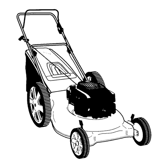
YARD MACHINES
OWNER'S GUIDE
MODEL SERIES
310-
329
AND
510 - 519
ROTARY
MOWER
Model 518 Shown
IMPORTANT:
READ SAFETY
RULES AND INSTRUCTIONS
CAREFULLY
Warning:
This unit is equipped with an internal combustion engine and should not be used on or near any unimproved forest-
covered, brush-covered
or grass-covered
land unless the engine's exhaust system is equipped with a spark attester meeting
applicable
local or state laws (if any).
If a spark arrester is used, it should be maintained in effective working order by the operator,
In the State of Catifornia the above is required by law (Section 4442 of the California
Public Resources Code). Other states may have
similar taws. Federal laws apply on federal lands. A spark arrester for the muffler is available through your nearest engine authorized
service dealer or contact the service department,
P.O. B_x 368022 Cleveland, Ohio 44136-9722.
MTD PRODUCTS
INC. P.O. BOX 368022 CLEVELAND,
OHIO 44136-9722
PRINTED IN U.S.A.
770-0273M
Advertisement
Table of Contents

Related Manuals for MTD 310 series


Summary of Contents for MTD 310 series
- Page 1 YARD MACHINES OWNER'S GUIDE MODEL SERIES 310- 510 - 519 ROTARY MOWER Model 518 Shown IMPORTANT: READ SAFETY RULES AND INSTRUCTIONS CAREFULLY Warning: This unit is equipped with an internal combustion engine and should not be used on or near any unimproved forest-...
- Page 2 SECTION 1: IMPORTANT SAFE OPERATION PRACTICES FOLLOWED, COULD ENDANGER THE PERSONAL SAFETY AND/OR PROPERTY OF YOURSELF WARNING: THIS SYMBOL POIrlTS OUT IMPORTANT SAFETY INSTRUCTIONS WHICH, IF NOT OTHERS. READ FOLLOW INSTRUCTIONS THIS MANUAL BEFORE ATTEMPTING OPERATE YOUR LAWN MOWER. FAILURE COMPLY WITH THESE...
-
Page 3: Slope Operation
• Never operate the mower in wet grass. Always be • Do not mow slopes greater than 15 degrees sure of your footing. A slip and fall can cause serious shown on the slope gauge. personal injury. Keep a firm hold on the handle and * Do not mow on wet grass. - Page 4 • Check the blade and engine mounting bolts nt frequent • Never attempt to make wheel or cutting height intervals for proper tightness. Also, visually inspect blade adjustment while the engine is running. for damage (e.g., bent, cracked or worn). REolace with •...
- Page 5 SIGHT AND HOLD THIS LEVEL WITH A VERTICAL TREE A POWER POLE A CORNER OF A BUILDING OR A FENCE POST "r 1.1.1 I&l 15° o ,,,,,, WARNING t,,,,9 u - Do not mow on inclines with a slope in excess of 15 degrees (a rise of approximately 2-1/2 feet every 10 feet).
- Page 6 SECTION 4: CONTENTS OF HARDWARE PACK MODEL 510 - 519 ONLY Remove this sheet from your o_mer's guide hardware fro_l AIATTACHING THE FRONT WHEELS hardware pack illustratio_ identification purposes. After assembly, keep the Slope Gauge which is on the reverse side of this sheet for future use. AXLE BOLTS (Hardware...
-
Page 7: Setting Up Mower
SECTION 5: SETTING UP MOWER This guide covers models 310 - 319 push mowers with soft top grass bags, 320 - 329 push mowers with hard top grass bags and models 510 - 518 high wheel push mowers with hard top bags. Much of this guide pertains to both models. -
Page 8: Installing The Wheels
Note: Make sure to route the cables nside the REAR WHEELS (Hardware B) lower handle. Also do not crimp the cables vrhile lifting the handle up. For shipping purposes, the lower handles _.re placed Axle,# Wave_ Cupped Flat on the unit with the hairpin clip on the outer role. Bolt Washer Wheel Washer •... -
Page 9: Grass Catcher
* Loosen the rope guide wing nut. • With the spark plug wire disconnected grounded, hold the blade control handle against the upper handle, and pull the starter rope out of the engine. • Check and make sure that the rope guide faces as shown in figure 7 so that the opening in the rope guide faces up. -
Page 10: Section 7: Operation
RECOIL STARTER SECTION 6: CONTROLS The recoil starter handle is attached to the handle, See figure 11. Stand behind the unit in the operating position to start the unit. Blade Control Handle Throttle Control HEIGHT ADJUSTERS The height adjusters determine the cutting height of the mower. -
Page 11: To Stop Engine
TO STOP ENGINE AND BLADE START ENGINE and ENGAGE BLADE • Release the blade control handle to stop the • Prime engine as instructed in the separate engine and blade. engine manual packed with your unit. • Move throttle control lever all the way forward. WARNING: •... -
Page 12: Height Adjustment
SECTION 8: ADJUSTMENTS WARNING: adjustment De not at any time r_ake any lawn mower witt-out first stopping engine disconnectirg spark plug wire. CUTTING HEIGHT ADJUSTMENT Nine position height adjusters. Each each space between each represents one of nine cutting positions available. -
Page 13: Throttle Control Adjustment
__15 HEIGHT ADJUSTMENT ° Remove the screw shown in figure 17. Remove the cable clamp from the cable. ° Push the throttle control lever on the handle all the way forward as far as it will go, then back it off one "click". -
Page 14: Section 9: Maintenance
SECTION 9: MAINTENANCE ENGINE LUBRICATION Follow engine manual for lubrication instructions. (Refer to figure 18.) WARNING: ground spark plug wire before disconnect spark plug wire before cleaning, sure disconnect WARNING: Always stop engi le performing any repairs or maintenance. lubricating or doing any kind of worm on lawn mowe r. -
Page 15: Blade Mounting
° Place the blade on the blade adaptor aligning the star in the blade with the star on adaptor. 1.Insert s crew driverthrough hole The side of the blade marked with the part number or bottom should be facing towards the ground. - Page 16 SECTION 10: OFF-SEASON STORAGE • Coat mower's cutting blade with chassis grease The following steps should be taken to prep_ re lawn to prevent rusting. mower for storage. • Store mower in a dry, clean area. Do not store • Clean lubricate mower thorou!thly...
- Page 17 SECTION 11: TROUBLE SHOOTING Trouble Possible Cause Corrective Action Engine fails to start Blade control handle disengaged. Engage blade control handle. Spark plug wire disconnected. Connect wire to spark plug, Throttle control lever not in correct Move throttle lever to correct starting starting position, position, Fuel tank empty, or stale fuel.
-
Page 18: Parts List
SECTION 12: ILLUSTRATED PARTS LIST Attachments 190-119-000 Grass Bag Kit 190-120-000 Mulching Kit 190-137-000 Side Discharge Kit... - Page 19 MODEL NUMBERS 320 - 329 REF. PART NO. DESCRIPTION PART NO DESCRIPTION 3824 710-1348 Screw AB 1/4-20 Control Handle Ass'y (Std) 3004 736-0356 Bell-Wash..39"1.D. Control Handle Ass'y (Deluxe) 1639 712-0798 Hex Nut 3/8-16 Trd, Baffle 3605 : Oval C-Sunk Mach.-Scr. 710-0654A Hex L-Wash, Hd.
- Page 20 Attachments 190-119-000 Grass Bag Kit 190-120-000 Mulching Kit 190-137-000 Side Discharge Kit...
- Page 21 MODELS 510 - 519 DESCRIPTION PART NO PART NO. DESCRIPTION -tex Nut 3/8-16 Trd. 712-0798 ..Control Handie AS;y (Std) ....747-0824 Hex L-Wash, Hd. Scr. 3/8-16x1" 710-0654A Control Handle Ass'y (Deluxe) 647-0004 682-0076 __1" D eck Ass'y Baffle 731-1639 Rear Flap 17.77 Lg.
-
Page 22: Engine Shrouds
WHEELCHART Models 510 - .= 19 Models 510 - 519 Rear Models 310 - 329 Front and Rear Front Bar Tread T-Tread S.Tread Bar Tread T-Tread BarTread Description T-I_ .=ad 734-1782 Wheels w/o Bearings - Beige 734-1781 734-1512A 734-1781 Wheels w!o Bearings - Gray 734-1841 Aero- Gray 734-1842... - Page 23 Copy the information from your model plate here! O00000EO00000 Model N,Jmber O00000EO00000 Serial Ni,mber O00000EO00000 "300)800-7310 For Parts, Accessories or Service Information Please have your model number ready when you call The only way to insure the performance of your product is to use original equipment parts and accessories.
Need help?
Do you have a question about the 310 series and is the answer not in the manual?
Questions and answers