
Subscribe to Our Youtube Channel
Related Manuals for McIntosh MA5200


Summary of Contents for McIntosh MA5200
-
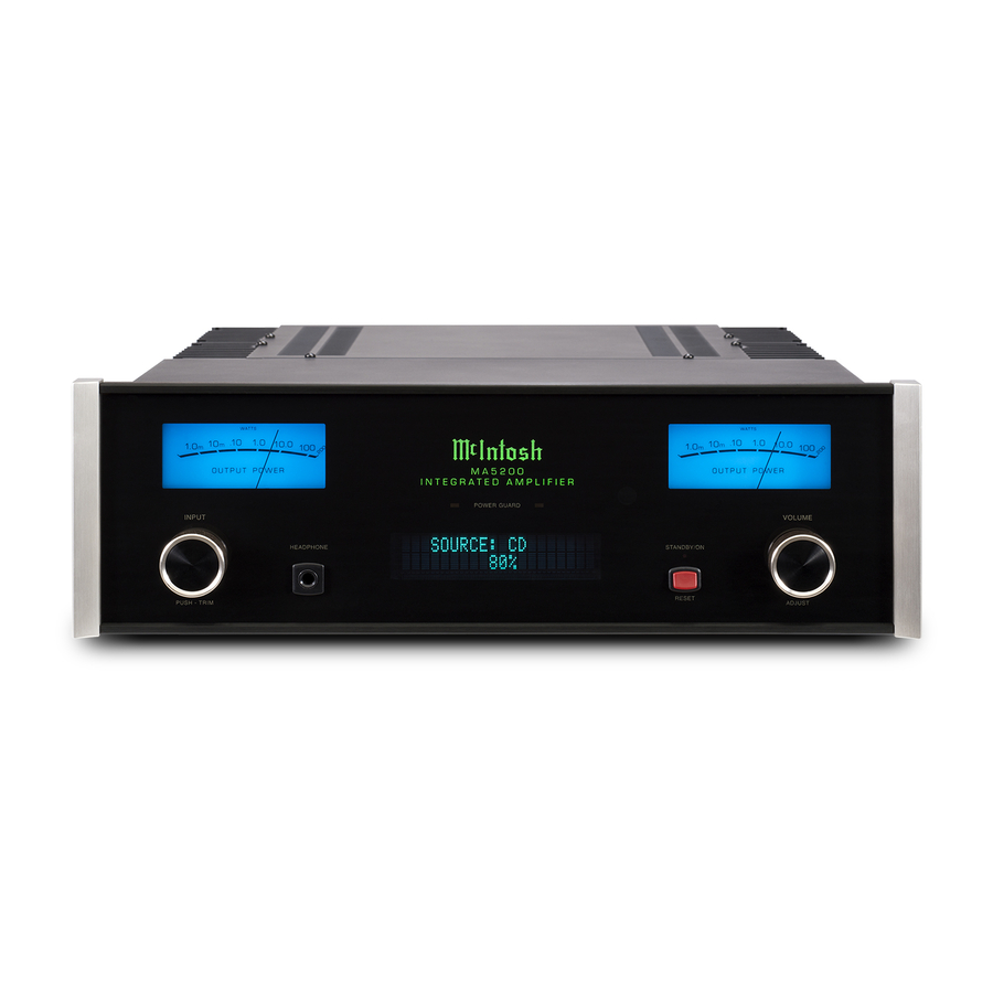
Page 1: Integrated Amplifier
McIntosh Laboratory, Inc. 2 Chambers Street Binghamton, New York 13903-2699 Phone: 607-723-3512 www.mcintoshlabs.com MA5200 Integrated Amplifier Owner’s Manual... -
Page 2: Safety Instructions
The lightning flash with arrowhead, within an equilateral The exclamation point within an equilateral triangle is triangle, is intended to alert the user to the presence of intended to alert the user to the presence of important uninsulated “dangerous voltage” within the product’s en- operating and maintenance (servicing) instructions in the closure that may be of sufficient magnitude to constitute literature accompanying the appliance. -
Page 3: Table Of Contents
Setup Mode: Your decision to own this McIntosh MA5200 Inte- If it is determined that your McIntosh product is in grated Amplifier ranks you at the very top among need of repair, you can return it to your Dealer. You How to Operate the Setup Mode ........ -
Page 4: General Information
MA5200. Power Output Meters on McIntosh Meter 8. The MA5200 Remote Control is capable of operat- 2. Apply AC Power to the MA5200 and other McIn- Power Amplifiers. A 3.5mm stereo Illumination Control ing other components. For additional information... -
Page 5: Introduction
Electromagnetic Switches on all inputs and operating tors with 60 Joules of Energy Storage and regulated MA5200, with a power output of 100 watts per chan- functions for reliable, noiseless, distortion free switch- Power Supply ensures stable noise free operation even nel, will drive a pair of quality Loudspeakers to a high ing. -
Page 6: Dimensions
Dimensions Dimensions The following dimensions can assist in determining the best location for your MA5200. There is additional information on the next page pertaining to installing the MA5200 into cabinets. Front View of the MA5200 " 44.5cm " 6" 13.7cm 15.2cm... -
Page 7: Installation
Installation Installation " 3/16 The MA5200 can be placed upright on a table or 43.7cm shelf, standing on its four feet. It also can be custom installed in a piece of furniture or cabinet of your choice. The four feet may be removed from the bottom... -
Page 8: Rear Panel Connections
IR McIntosh Component when the Loudspeaker Room Sensor MA5200 is switched On/Off Connect the MA5200 power cord DIGITAL AUDIO INPUTS DATA PORTS send signals RS232-C connector LEFT OUTPUT to a live AC outlet. Refer to infor- for components with Digital... -
Page 9: Connecting Components
7. Connect any additional McIntosh Components in Notes: 1. If the MA5200 is part of a Home Theater using the MA5200 Remote Control. With an external a similar manner, as outlined in steps 5 thru 6. -
Page 10: Passthru Connections
Passthru Connections Passthru Connections The MA5200 can be part of a Multichannel Sound System for SACD, DVD-Audio and Home Theater. A/V Control Center The Right and Left Front Channels from an Audio/ Video Control Center can “Passthru” the MA5200. In the following example the AUX Input will become the “Passthru”... -
Page 11: Connecting For Bi-Amplification
The MA5200’s Power Amplifier, together with an additional separate Power Amplifier, may be used to Bi-Amplify a Loudspeaker System. In the illustration on this page the Power Amplifier of the MA5200 is connected to the Midrange/High Frequency Section of the Loudspeaker. The additional separate Power Amplifier is connected to the Low Frequency Section of the Loudspeaker System. - Page 12 Technical Support. actual components would be connected in a similar 3. Banana plugs are for use in the United 5. Connect the MA5200 power cord to an active AC manner. For additional information refer to “Connec- States and Canada only.
-
Page 13: Connecting Loudspeakers
WARNING: Loudspeaker terminals are hazard- ous live and present a risk of electric shock. For additional instruction on making Loudspeaker Connections con- tact your McIntosh Dealer or McIn- tosh Technical Support. 7. Connect the MA5200 power cord to an active AC outlet. -
Page 14: Remote Control Push-Buttons
Scrolls through the available MA5200 Inputs Scrolls through the available Selects one of the eight MA5200 Inputs available Audio Sources Note: Push-buttons whose function is not identified above are for use with other McIntosh Products. -
Page 15: How To Use The Remote Control
Disc Player or Music Server is being used. MA5200 Data Ports. Notes: 1. If at any time the MA5200 seems unrespon- Tuner Push-buttons sive to HR072 Remote Control Commands Press the AM or FM Push-button to select the desired press the Push-button first. -
Page 16: Front Panel Displays, Controls, Push-Button And Jack
Connection for dynamic IR Sensor receives STANDBY/ON Push-button with indica- type headphones, for commands from a tor switches the MA5200 ON or OFF private listening Remote Control (Standby) and resets the microprocessors INFORMATION DISPLAY indicates the Sources, Volume, other Audio Settings,... -
Page 17: How To Operate The Setup Mode
McIntosh USB Audio vided to customize the operating settings using the V_._ _ V_.__ Front Panel Display. Refer to the MA5200 Front Panel MA5200 S/N: _ _ _ _ _ _ _ Figure 3 Illustration on the previous page while performing an McIntosh USB Audio V_.__... -
Page 18: Firmware Version
Notes: 1. Any one of the Default Inputs may be swiched Figure 5 Off. If any input is switched Off its name will er). The Version of the Firmwares in the MA5200 can The second example will illustrate reassigning the no longer appear on the Front Panel Display be identified at any time by utilizing the Setup Mode. -
Page 19: Source Input Renaming
Source Input Renaming TUNER “U” starts flashing. Refer to figure 11. The MA5200 Default Input Names (CD, AUX, DVD, etc. as indicated on the Front Panel Display) can be SETUP: SOURCE NAME customized with a different name up to nine charac- >>... -
Page 20: Passthru
3. To exit from the Setup Mode, press the INPUT “Passthru” the Preamplifier Circuitry of the MA5200, the MA5200 is used in the same location as another CONTROL and the Front Panel Display will revert and then on to the Power Amplifier Circuitry of the McIntosh Preamplifier and/or A/V Control Center, back to its normal display. -
Page 21: Power Mode
5. Press the VOLUME UP/DOWN Push-button on the Remote Control to verify proper operation. Power Mode The MA5200 incorporates an Auto Off Feature, which automatically places the preamplifier into the Power Saving Standby/Off Mode. This occurs approximately 30 minutes after there has been an absence of audible... -
Page 22: How To Operate The Ma5200
After approximately 5 seconds increasing to the last used volume setting. Refer to the Display returns to indi- figures 50, 51, 52 and 53. To switch OFF the MA5200, Trim Functions cate the Source Selection and press the STANDBY/ON Push-button on the Front The MA5200 has various Trim Selections with Ad- Volume Level. -
Page 23: Trim Level
Source Components can have slightly different volume Off Mode. Refer to figure 60. than the TUNER Input, so the trim level for levels resulting in the need to readjust the MA5200 the Server Input is reduced to -2.5 dB. Refer to OUTPUT MODE Volume Control when switching between different figure 58. -
Page 24: Display Brightness
The Front Panel Display Brightness may be changed DIGITAL AUDIO DISPLAY After approximately 5 seconds the Display will return from the default setting. The MA5200 will remem- By default the Digital Audio Display is switched Off. to indicate the Source Selection and Volume Level. -
Page 25: Trim, Mute, Headphone Jack
How to Operate the MA5200, con’t justing the volume control will un-mute the MA5200. and the audio will be muted. When the MA5200 has METER BACKLIGHT returned to a safe operating temperature, normal op- Lights: Headphones Jack eration will resume. -
Page 26: Optical And Coaxial Digital Inputs
Windows (XP with ® ® McIntosh Laboratory, Inc. 2 Chambers Street Binghamton, New York 13903-2699 Phone: 607-723-3512 www.mcintoshlabs.com Windows Driver Installation Service Pack 3, Vista with Service Pack 1 and Win- and Operation Guide” and “McIntosh USB Audio Optical and Coaxial Digital Inputs... -
Page 27: Resetting The Ma5200 To Default Settings
How to Operate the MA5200, con’t performing the following: 1. Press the STANDBY/ON Push-button until the STANDBY/ON Indicator switches Off. 2. When the MA5200 cycles On then Off, release the STANDBY/ON Push-button. 3. When the STANDBY/ON LED is illuminated press the STANDBY/ON Push-button, the MA5200 will resume normal operation. -
Page 29: Photos
Photos... -
Page 30: Specifications
Preamplifier Output Impedance +0, -3dB from 10Hz to 100,000Hz Standby: Less than 0.25 watt 220 ohms Note: Refer to the rear panel of the MA5200 for the cor- Preamplifier Output (for rated input) rect voltage. 1V (8V Maximun) Headphone Impedance... -
Page 31: Packing Instructions
#10 flat washer 1-3/4 inch needed, please call or write Customer Service Depart- 017937 Plastic foot ment of McIntosh Laboratory. Refer to page 3. Please 400159 #10-32 x 3/4 machine screw see the Part List for the correct part numbers. - Page 32 McIntosh Laboratory, Inc. 2 Chambers Street Binghamton, NY 13903 www.mcintoshlabs.com The continuous improvement of its products is the policy of McIntosh Laboratory Incorporated who reserve the right to improve design without notice. Printed in the U.S.A. McIntosh Part No. 04137600...
Need help?
Do you have a question about the MA5200 and is the answer not in the manual?
Questions and answers