Table of Contents
Advertisement
Advertisement
Table of Contents

Subscribe to Our Youtube Channel
Related Manuals for Rockford Fosgate OEQ2 HIGH


Summary of Contents for Rockford Fosgate OEQ2 HIGH
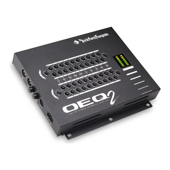
- Page 1 ERFORMANCE ARAMETRIC QUALIZER NSTALLATION & O PERATION ® ®...
- Page 2 Rockford Technical Training Institute (RTTI). Please read your warranty and retain your receipt and original carton for possible future use. To add the finishing touch to your new Rockford Fosgate image order your Rockford accessories, which include everything from T-shirts and jackets to hats and sunglasses.
-
Page 3: Table Of Contents
Installation Section of this manual or refer to the icons listed below. Other information can be located by using the Table of Contents. We, at Rockford Fosgate, have worked very hard to make sure all the information in this manual is current. But, as we are constantly finding new ways to improve our product, this information is subject to change without notice. -
Page 4: Introduction
N T R O D U C T I O N The OEQ is an octave equalizer used to help compensate for acoustical inaccuracies common in the automobile environment. The OEQ is a stereo equalizer with ten bands of frequency adjust- ment spaced at octave intervals. -
Page 5: Technical Design Features
ECHNICAL ESIGN EATURES High-Q Filters Hi-Q filters are utilized for adjusting narrow frequency bands in an equalizer. Filter “Q” or Quality Factor is a measure of the “narrow- ness” of the filter response. Using Low-Q (wide) filters in an equalizer allows adjustments made on one control to strongly effect neighbor- ing frequencies during boost or cut. -
Page 6: Design Features
ESIGN EATURES GND B+ REM LEFT RIGHT BYPASS BAL IN ENGAGE BAL OUT RIGHT LEFT RIGHT LEFT 1. RCA Input Jacks – The industry standard RCA jacks provide easy connections for signal level input. They are gold-plated to resist the signal degradation caused by corrosion. - Page 7 8. Output Level Attenuators – The Output Level Attenuators are used to cut the output level for matching the input of the amplifier. They can be adjusted to levels ranging from a minimum ratio of 1:0 (no output) to a maximum ratio of 1:1. 9.
-
Page 8: Installation Considerations
N S TA L L AT I O N O N S I D E R AT I O N S The following is a list of tools you will need for installing the OEQ Red power wire Wire strippers Blue remote turn-on wire Wire cutters Black grounding wire... -
Page 9: Mounting Location
OUNTING OCATION The mounting location for the OEQ should allow easy access to the controls for making necessary adjustments. The OEQ will most likely be adjusted only at the time of installation and will not need further adjustment unless changes to the audio system are performed. To ensure optimum performance, care should be taken when mounting the equal- izer in the following locations: Engine Compartment... - Page 10 of the wire. Insert the bared wire into the REM terminal of the power connector and fasten the screw. Total current consumption through this lead is negligible. The GND lead should be connected to the chassis ground of the vehicle. Prepare a length of cable (approximately 12" long) to be used for the ground lead by stripping 3/8"...
-
Page 11: Oeq 2 Installation
NSTALLATION ® ® Power Connections GND B+ REM LEFT RIGHT BYPASS BAL IN ENGAGE Less than 18" Connect to chassis ground of vehicle. Connect to remote – turn-on lead of source unit. Connect to B+ of battery with a 2 amp fuse. RCA Input Connections Input GND B+ REM... - Page 12 BLT Input Connections ® ® ® ® BALANCED LINE TRANSMITTER RCA Input BALANCED LINE INPUT OUTPUT Shield + L Signal + R Signal – R Signal – L Signal +15V –15V GND B+ REM LEFT RIGHT BYPASS BAL IN ENGAGE •...
- Page 13 RCA Output Connections ® ® BAL OUT RIGHT LEFT RIGHT LEFT • RCA Outputs are configured in parallel • Use either RCA Output for input of next component Balanced Output Connections Shield + L Signal + R Signal – R Signal –...
- Page 14 Level Setting the OEQ CLOCK AUTO ILLUM DISC DSPL P.SCN LOUD AMFM LD RDM TUNE D.SCN SCAN PAUSE ® ® 1kHz Test Tone @ “0dB” ® ® H i g h P e r f o r m a n c e P a r a m e t r i c E q u a l i z e r Set the Gain Controls on the amplifier(s) as well as the input gain and to minimum .
- Page 15 Level Setting the OEQ with a BLT CLOCK AUTO ILLUM DISC DSPL P.SCN LOUD AMFM LD RDM TUNE D.SCN SCAN PAUSE ® ® 1kHz Test Tone @ “0dB” ® ® BALANCED LINE TRANSMITTER – ® ® H i g h P e r f o r m a n c e P a r a m e t r i c E q u a l i z e r 1.
-
Page 16: Oeq 2 Operation
PERATION Boost/Cut Control The Boost/Cut controls are used to increase or reduce emphasis in a specific octave of music. Each control provides up to 12dB of boost or cut to the selected frequency. The following graph shows the effect of each control at the full boost (+12dB) and full cut (–12dB) positions. - Page 17 Frequency Warp Control The Frequency Warp controls are used to fine adjust the center frequency of the Boost/Cut controls. Each Warp control allows for a range of 1/2 octave above and below the center frequency. The following graph illustrates the operating range of the 1kHz Warp control at its minus (–), center (•), and plus (+) positions.
- Page 18 Engage/Bypass Switch The Engage/Bypass Switch is useful in system tuning when comparing the differences between an equalized and non-equalized system. With the switch in the IN position, all EQ functions are engaged and can be heard. With the switch in the OUT position, all EQ functions except the input gains and output attenuators are bypassed from the signal path.
-
Page 19: System Diagrams
Y S T E M I A G R A M S RCA Input/RCA Output CLOCK AUTO ILLUM DISC DSPL P.SCN LOUD AMFM LD RDM TUNE D.SCN SCAN PAUSE ® ® RCA Input located in front of vehicle RCA Output ®... - Page 20 RCA Input/Balanced Output CLOCK AUTO ILLUM DISC DSPL P.SCN LOUD AMFM LD RDM TUNE D.SCN SCAN PAUSE ® ® RCA Input located in front of vehicle Balanced Output ® ® ® Tweeter Tweeter Midrange Midrange – 17 –...
- Page 21 Balanced Input/RCA Output CLOCK AUTO ILLUM DISC DSPL P.SCN LOUD AMFM LD RDM TUNE D.SCN SCAN PAUSE ® ® Optional Balanced ® ® BALANCED LINE TRANSMITTER Line Transmitter Balanced Output located in rear of vehicle RCA Output ® ® ® ®...
- Page 22 Balanced Input/RCA & Balanced Output CLOCK AUTO ILLUM DISC DSPL P.SCN LOUD AMFM LD RDM TUNE D.SCN SCAN PAUSE ® ® ® ® BALANCED LINE TRANSMITTER Optional Balanced Line Transmitter Balanced Input located in rear of vehicle RCA Output RCA Output Balanced Output ®...
-
Page 23: Rockford Fosgate Accessories
The Balanced Line Transmitter converts signal RCA cables from the source unit to balanced signals. The BLT improves sound quality in the system by eliminating noises generated by vehicle electrical systems. The BLT is available for Rockford Fosgate products that offer a balanced input. Extra Balanced Cables (RP4205) ®... -
Page 24: Troubleshooting
R O U B L E S H O O T I N G TROUBLE-S Symptom Diagnosis Remedy does not Voltage applied to the Check the alternator, bat- turn on (Power REM terminal of the tery, fuse and wiring and LED is off) is not between 5 repair as necessary. - Page 25 TROUBLE-S Symptom Diagnosis Remedy Turn-On Pop Voltage spike from out- Disconnect input signal to put of preceding com- and turn OEQ on and ponent is entering OEQ off. If noise is eliminated, con- through input signal nect REM lead of OEQ remote turn-on wire with a delay module.
- Page 26 Select the Signal Input Switch Signal Input switch not Engine Noise for “BAL” input. (BLT Input) selected for BLT input. • If noise persists, see your Authorized Rockford Fosgate Dealer. – 23 –...
-
Page 27: Specifications
P E C I F I C A T I O N S Operating Voltage +10V to +16VDC Current Consumption 500mA B+ Fuse Size (internal) 2 Amp Fuse Type Frequency Response 20-20kHz 0.1dB Signal-to-Noise Ratio >98dBA Distortion (THD + Noise) 0.02% Input Impedance Output Impedance... -
Page 28: Warranty Information
Electronics found to be defective during the warranty period will be repaired or replaced at Rockford Fosgate’s discretion. Repaired or replaced electronics will be covered by the balance of the original warranty period only. Rockford Fosgate shall not be responsible for any incidental or consequential damages resulting from a defect in electronics. -
Page 29: International Information
– 26 –... - Page 30 Lea detenidamente las siguientes instrucciones de instalación del producto. NTRODUCCIÓN El OEQ es un ecualizador de octava que se ha de utilizar para compensar las inexactitudes acústicas comunes en el interior de los automóviles. El OEQ es un ecualizador estereo con ajustes en diez bandas de frecuencia espaciadas en intervalos de una octava.
- Page 31 NSTALACION DEL Conexiones de entrada RCA Entrada GND B+ REM LEFT RIGHT BYPASS BAL IN ENGAGE • Conecte las salidas RCA de su fuente de sonido a las entradas LEFT IN y RIGHT IN del OEQ • El conmutador SIGNAL INPUT ha de estar no pulsado cuando utilice entradas RCA Conexiones de entrada BLT ®...
- Page 32 Veuillez lire les instructions suivantes pour l'installation de ce produit. Ne pas les suivre pourrait causer des blessures ou endommager le véhicule. N T R O D U C T I O N L'OEQ est un égaliseur d'octave destiné à compenser les différences acoustiques dans l'environnement automobile.
- Page 33 NSTALLATION DU Connections d'entrée RCA Entrée GND B+ REM LEFT RIGHT BYPASS BAL IN ENGAGE • Les sorties RCA de la source se branchent sur l'entrée LEFT IN (gauche) et RIGHT IN (droite) du OEQ • Le commutateur de signal d'entrée doit être en position sortie Connections d'entrée BLT ®...
- Page 34 Bitte lesen Sie die folgende Gebrauchsanleitung sorgfältig durch. Dies kann Sie und das Produkt vor Fehlern oder sogar vor Beschädigung schützen. INLEITUNG Der OEQ ist ein parametrischer Equalizer der Akustische Probleme Ihrer Anlage oder Ihres Fahrzeuges ausbessern soll. Der OEQ ist ein 10 Band Stereo Equalizer bei dem einzeine Frequenzbänder, unterteilt in interval-Oktaven eingestellt werden kônnen.
- Page 35 INBAU Chinch-Eingangs Buchsen Chinch Eingänge GND B+ REM LEFT RIGHT BYPASS BAL IN ENGAGE • Chinch-Ausgänge der Signalquelle rechts und links mit right in und left in verbinden • Signal-Eingangsschalter auf out für Chinch-Eingang stellen BLT Eingang ® ® BALANCED LINE TRANSMITTER RCA Input BALANCED LINE INPUT...
- Page 36 Leggere attentamente le istruzioni riportate in questo manuale. Non osservare le correte procedure di impiego puó provacare danni al veicolo o a voi stessi. NTRODUZIONE é un equalizzatore ad ottave impiegato per compensare i difetti acustici tipici dell'interno delle automobili. OEQ é...
- Page 37 'OEQ NSTALLAZIONE DELL Connessione degli ingressi RCA Intresso GND B+ REM LEFT RIGHT BYPASS BAL IN ENGAGE • Le uscite RCA della sorgente vengono collegate agli ingressi LEFT IN e RIGHT IN dell'OEQ • Lo switch deve essere nella posizione RCA (rilasciato) Connessione dell'ingresso bilanciato BLT ®...
- Page 38 OTES...
- Page 39 OTES...
- Page 40 Rockford Fosgate Rockford Corporation 546 South Rockford Drive Tempe, Arizona 85281 U.S.A. In U.S.A., (602) 967-3565 In Europe, Fax (49) 4207-801250 In Japan, Fax (81) 559-79-1265 2/96 MAN-1135-A...
Need help?
Do you have a question about the OEQ2 HIGH and is the answer not in the manual?
Questions and answers