Table of Contents
Advertisement
Your new table saw has been engineered and manufactured to our high standards for dependability, ease of operation, and
operator safety. When properly cared for, it will give you years of rugged, trouble-free performance.
WARNING:
To reduce the risk of injury, the user must read and understand the operator's manual before using this
product.
Thank you for buying a RIDGID product.
SAVE THIS MANUAL FOR FUTURE REFERENCE
OPERATOR'S MANUAL
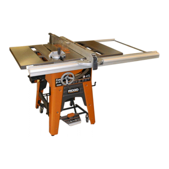
10 in. CAST IRON TABLE SAW
TS3650
Advertisement
Table of Contents

Related Manuals for RIDGID TS3650


Summary of Contents for RIDGID TS3650
- Page 1 When properly cared for, it will give you years of rugged, trouble-free performance. WARNING: To reduce the risk of injury, the user must read and understand the operator’s manual before using this product. Thank you for buying a RIDGID product. SAVE THIS MANUAL FOR FUTURE REFERENCE...
-
Page 2: Table Of Contents
TABLE OF CONTENTS n Introduction ..................................2 n General Safety Rules ..............................3-4 n Specific Safety Rules..............................4-5 n Symbols..................................6-7 n Electrical ..................................8-10 n Glossary of Terms ................................11 n Features ..................................12-13 n Tools Needed ................................. 14 n Loose Parts................................15-16 n Assembly ...................................17-27 n Operation ...................................28-39 n Adjustments................................40-46 n Maintenance ................................... -
Page 3: General Safety Rules
GENERAL SAFETY RULES n DRESS PROPERLY. Do not wear loose clothing, gloves, WARNING: neckties, or jewelry. They can get caught and draw you into moving parts. Rubber gloves and nonskid footwear Read and understand all instructions. Failure are recommended when working outdoors. Also wear to follow all instructions listed below, may result protective hair covering to contain long hair. -
Page 4: Specific Safety Rules
GENERAL SAFETY RULES n BEFORE MAKING A CUT, BE SURE ALL n USE OUTDOOR EXTENSION CORDS. When tool is ADJUSTMENTS ARE SECURE. used outdoors, use only extension cords with approved ground connection that are intended for use outdoors n AVOID CUTTING NAILS. Inspect for and remove all and so marked. - Page 5 SPECIFIC SAFETY RULES n SUPPORT LARGE PANELS. To minimize risk of blade n MOVE THE RIP FENCE out of the way when cross- pinching and kickback, always support large panels. cutting. n NEVER use rip fence as cutoff gauge when n REMOVE ALL FENCES AND AUXILIARY TABLES crosscutting.
-
Page 6: Symbols
SYMBOLS Some of the following symbols may be used on this tool. Please study them and learn their meaning. Proper interpreta- tion of these symbols will allow you to operate the tool better and safer. SYMBOL NAME DESIGNATION/EXPLANATION Volts Voltage Amperes Current Hertz... -
Page 7: Save These Instructions
SYMBOLS The following signal words and meanings are intended to explain the levels of risk associated with this product. SYMBOL SIGNAL MEANING Indicates an imminently hazardous situation, which, if not avoided, will DANGER: result in death or serious injury. Indicates a potentially hazardous situation, which, if not avoided, could WARNING: result in death or serious injury. -
Page 8: Electrical
ELECTRICAL EXTENSION CORDS SPEED AND WIRING Use only 3-wire extension cords that have 3-prong ground- The no-load speed of this tool is approximately 3450 rpm. ing plugs and 3-pole receptacles that accept the tool's plug. This speed is not constant and decreases under a load or When using a power tool at a considerable distance from the with lower voltage. - Page 9 ELECTRICAL WARNING: GROUNDING To prevent possible electrical hazards, have a qualified electrician check the line if you are not certain that it is properly wired. CHANGING MOTOR VOLTAGE See Figures 2 - 4. COVER OF GROUNDED WARNING: OUTLET BOX Electric shock can kill. To reduce the risk of seri- ous personal injury, never connect plug to power source until all assembly steps are completed.
- Page 10 ELECTRICAL MOTOR THERMAL OVERLOAD PROTECTOR JUNCTION See Figure 5. Your table saw comes equipped with a manual-reset thermal- overload protector designed to open the power line circuit MANUAL RESET when the motor temperature exceeds a safe level, when motor BUTTON is overloaded, or when a low voltage condition exists.
-
Page 11: Glossary Of Terms
GLOSSARY OF TERMS Anti-Kickback Pawls (radial arm and table saws) Non-Through Cuts A device which, when properly installed and maintained, Any cutting operation where the blade does not extend is designed to stop the workpiece from being kicked back completely through the thickness of the workpiece. toward the front of the saw during a ripping operation. -
Page 12: Features
FEATURES PRODUCT SPECIFICATIONS Blade Diameter...........10 in. (254 mm) Rating ....120 Volts, 60 Hz, AC Only, 13 Amperes 240 Volts, 60 Hz, AC Only, 6.5 Amperes Blade Arbor ..........5/8 in. (16 mm) Output Speed .............3,450/min. Cutting Depth at 0°....... 3-3/8 in. (85.7 mm) Net Weight.......... - Page 13 FEATURES KNOW YOUR TABLE SAW BLADE GUARD - Always keep the guard down over the blade for through-sawing cuts. See Figure 6. BLADE HEIGHT LOCK KNOB - This knob, in the center of the Before attempting to use this product, familiarize yourself height adjusting handwheel, locks the handwheel into place with all operating features and safety rules.
-
Page 14: Tools Needed
TOOLS NEEDED The following tools (not included) are needed for assembly and alignment: HAMMER COMBINATION WRENCH (9) (10 mm, 11 mm, 12 mm, 13 mm, 14 mm,17 mm, 1/2 in., 9/16 in. 11/16 in.) COMBINATION SQUARE PLIERS FRAMING SQUARE SCREWDRIVER (2) (SMALL AND MEDIUM) ADJUSTABLE WRENCH PHILLIPS SCREWDRIVER... -
Page 15: Loose Parts List
LOOSE PARTS LIST Fig. 8 Description Qty. Description Qty. Miter Gauge ............1 Back Rail ............1 Guard Support Assembly........1 Table Extension ...........2 Blade Guard Assembly........1 Motor..............1 Blade Wrench .............2 Belt Guard ............1 Rip Fence ............1 Drive Belt.............1 Bevel Adjusting Handwheel .......1 Spacer Bar ............1 Height Adjusting Handwheel......1 Front End Cap (left and right) ......2... - Page 16 LOOSE PARTS LIST Fig. 9 Description Qty. Leg ..................................4 Front Brace ................................1 Back Brace................................1 Side Brace ................................2 Leveling Feet.................................4 Foot Brace ................................4 Rear Tube................................2 Front Tube ................................2 Swivel Caster ................................4 Leg Bracket................................4 Rip Fence Storage Hooks.............................2 Miter Gauge Storage Hook ...........................1 Center Brace .................................1 Unlock Pedal Assembly ............................1 U-Bolt..................................1...
-
Page 17: Assembly
ASSEMBLY UNPACKING n Attach a second leg piece to the other side of the front brace using two carriage bolts and flanged hex nuts. This product requires assembly. n Repeat the above steps once for the back brace. n Remove the packing materials from around your tool. Do n Secure the miter gauge storage hook to the leg on the not discard the packing material until you have carefully left side of the leg stand using a carriage bolt and flanged... - Page 18 Fig. 12 NOTE: The front panel is the one with the Ridgid logo and must be on the front of the saw base. n Insert a screw through the hole in the saw base and the hole in the leg stand.
- Page 19 ASSEMBLY HERC-U-LIFT™, LOWER SECTION TO INSTALL THE HERC-U-LIFT™ MOBILE BASE TO THE LEG STAND TUBE HEX NUT SCREW See Figures 14 - 16. SUPPORT (1/4-20 x 2 in.) WARNING: Do not lift the saw without help. Hold it close to your body.
- Page 20 ASSEMBLY of the tube of the lower section as shown in figure 15. CENTER U-BOLT WITHIN THE LATCH MECHANISM Secure using the flat washer and lock nut. NOTE: Tighten the lock nuts until flush with the bottom UNLOCK of the screw. The screw should freely pivot. PEDAL n Repeat above step for the upper section of the Herc-U- Lift™.
-
Page 21: To Install Front And Back Rails
ASSEMBLY TO INSTALL FRONT AND BACK RAILS See Figures 19 - 21. To Install Front Rail: n Insert square head bolts (5/16-18 x 1 in.) into the holes on the front of the saw table and extension tables. SQUARE n Attach flanged hex nut loosely allowing the square bolt HEAD head to protrude. - Page 22 ASSEMBLY TO ADJUST FRONT AND BACK RAILS FRONT See Figures 22 - 24. RAIL WARNING: The front and back rails must be aligned with the saw blade. Misalignment could cause binding or kickback. Failure to heed this warning could result in serious personal injury. REAR To Check Saw Blade Alignment before Adjusting RAIL...
- Page 23 ASSEMBLY n Position the rip fence over the right miter gauge groove. Place the front of the rip fence on the front rail before lowering the back of the rip fence onto the back rail. n Open this Operator's Manual so that eight pages are separated from the rest.
-
Page 24: To Install Blade Guard Assembly
ASSEMBLY TO INSTALL SPACER BAR See Figure 28. LOCKING PLATE n Locate the following hardware: 1 spacer bar 2 locking plates 2 set screws SHIMS SPACER BAR n Thread one of the set screws into each of the locking plates. n Place one locking plate over each end ot the spacer bar with the bent ends pointing out. - Page 25 ASSEMBLY TO MOUNT MOTOR ASSEMBLY See Figure 31. n Loosen the two hex head screws that lock the pins in the mounting brace. n Insert the two pins on the motor assembly into the holes in the mounting brace. Push in as far as it will go. n DO NOT tighten screws at this time.
- Page 26 ASSEMBLY TO INSTALL SWITCH ASSEMBLY FRONT RAIL See Figure 38. NOTE: The switch assembly may be mounted on either the right or the left side of the saw. n Locate the following hardware: 1 switch key PAN HEAD 2 pan head screws with lock washers (10-32 x 3/8 in.) SCREW 2 square nuts (10 x 32) n Insert the pan head screws with lock washers (10-32 x...
- Page 27 ASSEMBLY TO ADJUST BLADE DEPTH BEVEL LOCK LEVER See Figure 41. The saw blade depth should be set so that the outer points of the saw blade are higher than the workpiece by approximately 1/8 in. to 1/4 in. but the lowest points (gullets) are below the workpiece.
-
Page 28: Operation
OPERATION Kickback can be caused by any action that pinches the WARNING: blade in the wood, such as the following: n Making a cut with incorrect blade depth Do not allow familiarity with tools to make you careless. Remember that a careless fraction of a n Sawing into knots or nails in the workpiece second is sufficient to inflict serious injury. -
Page 29: How To Make A Featherboard
OPERATION HOW TO MAKE A FEATHERBOARD See Figure 45. The featherboard is an excellent project for your saw. Select a solid piece of lumber approximately 3/4 in. thick, 3-5/8 in. wide and 18 in. long. Mark the center of the width on one end of the PUSH STICKS stock. - Page 30 OPERATION TYPES OF CUTS See Figure 46. There are six basic cuts: 1) the cross cut, 2) the rip cut, 3) the miter cut, 4) the bevel cross cut, 5) the bevel rip cut, and 6) the compound (bevel) miter cut. All other cuts are combinations of these basic six.
- Page 31 OPERATION TO USE THE HERC-U-LIFT™ MOBILE BASE TO MOVE THE TABLE SAW See Figure 47. WARNING: To avoid possible injury and before attempting to move the table saw, unplug the saw from the power supply and remove the switch key. UNLOCK PEDAL To activate the Herc-U-Lift™...
- Page 32 OPERATION TO USE THE MICRO-ADJUST FEATURE ON THE RIP FENCE See Figures 49 - 50. The rip fence that comes with this table saw has a feature that allows the user to make one-handed adjustments. To use the micro-adjust feature on the right-hand side of the saw blade: n Unlock the locking lever by pulling the lever up.
-
Page 33: Making Cuts
OPERATION MAKING CUTS CROSS CUT The blade provided with your saw is a high-quality combi- PLACE HANDS ON nation blade suitable for ripping and crosscut operations. WORKPIECE AND MITER GAUGE LOCK KNOB Carefully check all setups and rotate the blade one full revolution to assure proper clearance before connecting saw to power source. - Page 34 OPERATION TO MAKE A RIP CUT n Place a support (the same height as saw table) behind the saw for the cut work. See Figure 54. n Make sure the wood is clear of the blade before turning on the saw. WARNING: n Let the blade build up to full speed before moving the Make sure the blade guard assembly is installed...
- Page 35 OPERATION TO MAKE A BEVEL CROSS CUT n Turn the bevel lock lever to the right to unlock it then turn the bevel adjusting handwheel until the bevel indicator is See Figures 56 - 57. at the desired angle. n Set the blade to the correct depth for the workpiece and WARNING: push the bevel lock lever to the left to relock it.
- Page 36 OPERATION BEVEL RIP CUT n If ripping a piece larger than 36 in. long, place a support the same height as the table surface behind the saw for BLADE the cut work. ANGLED n Make sure the wood is clear of the blade before turning on the saw.
- Page 37 OPERATION LARGE PANEL CUT n Advance the workpiece and the miter gauge toward the blade. Keep the workpiece flush against the miter gauge. Stand slightly to the side of the wood as it contacts the RIP FENCE blade to reduce the chance of injury should kickback occur.
- Page 38 OPERATION TO MAKE A NON-THROUGH CUT NON-THROUGH CUT See Figure 61. Non-through cuts can be made with the grain (ripping) or BLADE across the grain (crosscut). The use of a non-through cut is PUSH STICK GUARD essential to cutting grooves, rabbets, and dadoes. This is the REMOVED only type cut that is made without the blade guard assembly installed.
- Page 39 OPERATION TO MAKE A DADO CUT DADO CUT See Figure 62. An optional dado throat plate is required for this procedure (see the Accessories section of this manual and check with the retailer where the table saw was purchased). All blades and dado sets must not be rated less than the speed of this tool.
-
Page 40: Adjustments
ADJUSTMENTS n The zero clearance throat plate must be level with the WARNING: saw table; adjust four set screws as needed. Before performing any adjustment, make sure NOTE: If necessary, adjust the side positioning set screw the tool is unplugged from the power supply and found on the edge of the zero clearance throat plate to the switch is in the OFF ( O ) position. - Page 41 ADJUSTMENTS n Reinstall blade guard assembly. BLADE n Check all clearances for free blade rotation. WRENCH n Plug in the saw and turn the switch on. n Slowly and cautiously raise the saw blade into the zero clearance throat plate. TO REPLACE THE SAW BLADE See Figures 65 - 66.
- Page 42 ADJUSTMENTS TO SQUARE THE SAW BLADE TO THE MITER GAUGE GROOVE See Figures 67 - 69. If the saw blade is not square to the miter gauge groove, do the following: n Unplug the saw and remove the switch key. n Tighten the bevel lock lever located at the front of the saw.
- Page 43 ADJUSTMENTS TO SET THE BEVEL INDICATOR AND BEVEL STOPS AT 0˚ AND 45˚ See Figures 70 - 73. To Check for Squareness, 90˚ Position: n Unplug the saw and remove the switch key. n Raise the blade to a 3 in. depth of cut. n Push the bevel lock lever counterclockwise to loosen the tilt clamp screw.
- Page 44 ADJUSTMENTS n Reinstall the height adjusting handwheel. BLADE AT 45˚ POSITION n With the saw blade at 45˚, the bevel indicator should be pointing to 45˚. n If not, remove the height adjusting handwheel. n Loosen the two screws on the scale and adjust the scale up or down until the bevel indicator points to 45˚.
- Page 45 ADJUSTMENTS TO ALIGN AND ADJUST THE RIP FENCE See Figures 77 - 79. The rip fence must be parallel with the saw blade and the miter gauge grooves. WARNING: A misaligned rip fence can cause kickbacks and LOCKING jams. To reduce the risk of injury, aways maintain LEVER proper rip fence alignment Fig.
- Page 46 ADJUSTMENTS TO ADJUST THE RIP FENCE INDICATOR See Figure 80. The rip fence has two indicators: one for use when the rip fence is on the right side of the saw blade and one for use when the rip fence is on the left side of the saw blade. NOTE: The blade guard assembly must be removed to per- form this adjustment.
-
Page 47: Maintenance
Herc-U-Lift™ Mobile Base. Grease caster ball bearings and oil caster axle as needed. When servicing, use only identical RIDGID re- n To maintain the table surfaces and rails, periodically placement parts. Use of any other parts may apply paste wax to them and buff to provide smooth create a hazard or cause product damage. -
Page 48: Troubleshooting
TROUBLESHOOTING Problem Solution Cause Excess vibration. Blade is out of balance. Replace blade. Blade is damaged. Replace blade. Saw is not mounted securely. Tighten all hardware. Work surface is uneven. Reposition on flat surface. Blade is warped. Check saw blade installation. Rip fence does not move smoothly. - Page 49 TROUBLESHOOTING Problem Solution Cause Saw does not make 90˚ or 45˚ cuts. Bevel stops not properly adjusted. See "To Set the Bevel Indicator and Bevel Stops at 0˚ and 45˚" in the Adjustments section. See "To Adjust the Miter Gauge" in the Miter gauge is misaligned (Miter Adjustments section.
- Page 50 NOTES...
-
Page 51: Warranty
This warranty on RIDGID Hand Held and Stationary Power ® chase. One World Technologies, Inc. and Ridgid, Inc. are not Tools covers all defects in workmanship or materials and nor- responsible for direct, indirect, incidental or consequential mal wear items such as brushes, chucks, motors, switches, damages. -
Page 52: Parts Ordering/Service
TS3650 CUSTOMER SERVICE INFORMATION For parts or service, contact your nearest RIDGID authorized service center. Be sure to provide all relevant information when you call or visit. For the location of the authorized service center nearest you, please call 1-866-539-1710 or visit us online at www.ridgidwoodworking.com.
Need help?
Do you have a question about the TS3650 and is the answer not in the manual?
Questions and answers
Need to replace rip fence Brocken plastic front locking Handel ,TS3650 10” table saw