Horstmann Electronic 7 Installation Instructions
Is an advanced water heating control
Hide thumbs
Also See for Electronic 7:
- Installation manual ,
- User operating instructions manual (9 pages) ,
- User instructions (3 pages)
Advertisement
Quick Links
Mounting
The Electronic 7 should be removed from the mounting box by unscrewing the 2 captive screws
securing the unit.
Conduit Box Mounting
Use either holes marked 'A' in Fig.1 to secure to a single gang box, or the two holes marked 'C' for
a double gang box. Cable entry is through the cut-out between the 2 fixing holes 'A'.
Surface Mounting
Use the two holes marked 'B' in Fig. 1 Cable entry is through the most appropriate cut-out
REMOVE THE APPROPRIATE CABLE ENTRY CUT-OUTS BEFORE FIXING THE BOX. WHERE POSSIBLE
DRILL THE BOX TO PROVIDE A CLOSE FITTING ENTRY FOR CABLES AND HEAT-RESISTANT FLEXIBLE CORDS.
TAKE CARE TO REMOVE SHARP EDGES.
2
Connections
Use a three-core cable with a minimum conductor size of
1.Omm for a 2kW heater, or 1.5mm for a 3kW heater to
connect the unit to the supply. Connect the incoming wires
to the terminal block as follows;
TERMINAL 1 - LIVE in
TERMINAL 2 - NEUTRAL in
TERMINAL 3 - NEUTRAL(s) out to immersion heater(s)
TERMINAL 4 - LIVE out to Boost immersion heater
TERMINAL 5 - LIVE out to Off-Peak immersion heater
Link terminals 4 & 5 when using
Clamp all surface wiring adjacent to the box or use
trunking where appropriate. Secure the heat resistant flexible cords from the immersion heaters
using the cable clamp in the box.
Single Element Immersion Heaters
The 3 core flexible cord should be heat-resistant and rated to 85°C.
TERMINAL 4 (Boost live output) should be connected to TERMINAL 5 (Off-Peak live output) and to
the immersion heater.
The Neutral connection should go to TERMINAL 3 and the Earth connection to the EARTH TERMINALS.
Dual Element Immersion Heaters
The elements should be controlled through separate thermostats. In practice the thermostat for the
top (short) element is usually set 5-10°C less than the thermostat for the long Off-Peak element.
The 3 core flexible cords should be heat-resistant and rated 85°C.
TERMINAL 4 (boost live output) should be connected to the short element and TERMINAL 5 (Off-
Peak live output) to the long element.
The Neutral connections should go to TERMINAL 3 and the Earth connection to the EARTH
TERMINALS.
Twin Immersion Heaters
The thermostat for the top immersion element should be set lower than the thermostat for the
bottom immersion heater.
The 3 core flexible cords should be heat-resistant and rated 85ºC. TERMINAL 4 (boost live output)
should be connected to the top immersion heater and TERMINAL 5 (off-peak live output) to the
bottom immersion heater. The two Neutral connections should go to TERMINAL 3 and the Earth
connections to the EARTH TERMINALS.
When wiring is complete ensure that all terminal screws, including the earth terminal screws are
securely tightened to achieve a minimum torque of .75Nm
3
Commissioning Instructions
The commissioning switch is on the rear of the unit (once removed from the back box)
and must now be set to achieve the correct operation of the controller and to engage the
BATTERY RESERVE.¹ The display will remain blank with the switch in the "OFF" position.
It is essential that the correct commissioning switch position is selected. Incorrect setting of the
commissioning switch may result in inefficient use of the available off-peak supply.
On installation the installer needs to select whether the Electronic 7 will switch at GMT times
throughout the year or whether the timings need to alter as the clocks change.
For example:
a single immersion heater
GMT/BST – Switching time will be changed by one hour. In the GMT/BST mode the clock display will
match the actual switching time.
GMT ONLY – Switching will always take place at GMT times (summer and winter). The clock display
will tell the correct time of day.
If Connection is to be made where a 2-Rate electricity meter is controlled by a Radio Teleswitch or
other equipment which control tariffs remotely or seasonally, it is essential that before setting the
commissioning switch you find out how the off-peak times are controlled.
The Customer Service Centre of your Electricity Supplier will confirm information regarding Off-Peak
electricity timing and the switching method used for your area.
On installations where the 2-Rate electricity meter is controlled by a mechanical Tariff Timeswitch
the commissioning switch should be set to GMT ONLY.
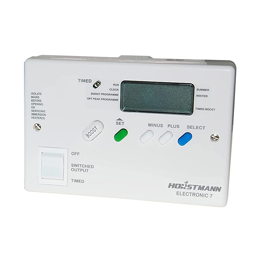
TIMED
BOOST PROGRAMME
ISOLATE
OFF PEAK PROGRAMME
MAINS
BEFORE
OPENING
OR
Time Display
SERVICING
IMMERSION
The Electronic 7 is fitted with an automatic clock that is pre-set on manufacture and should not
HEATER(S)
normally require any adjustments by the user.
The clock will automatically adjust the time to Summertime (BST) or Wintertime (GMT) as
appropriate and this setting is always shown on the clock display.
No adjustment is needed to be made by the installer/user.
OFF
SWITCHED
OUTPUT
TIMED
4
RUN
SUMMER
AM
CLOCK
WINTER
TIMED BOOST
SET
MINUS PLUS
SELECT
Advertisement

Subscribe to Our Youtube Channel
Related Manuals for Horstmann Electronic 7


Summary of Contents for Horstmann Electronic 7
- Page 1 SERVICING The thermostat for the top immersion element should be set lower than the thermostat for the IMMERSION The Electronic 7 is fitted with an automatic clock that is pre-set on manufacture and should not MINUS PLUS SELECT bottom immersion heater.
- Page 2 Live Parts - Enclosed button button to take you to unit. If the ELECTRONIC 7 is to be connected to a ring main then the spur feeding the controller Pollution degree 2 the 1st off time should be protected in the same way.
Need help?
Do you have a question about the Electronic 7 and is the answer not in the manual?
Questions and answers