
Related Manuals for Fluke QED 6


Summary of Contents for Fluke QED 6
- Page 1 QED 6 Defibrillator Analyzer Users Guide PN 2204510 September 2007 © 2007 Fluke Corporation, All rights reserved. Printed in USA All product names are trademarks of their respective companies.
- Page 2 Fluke Biomedical. This warranty covers the original purchaser only and is not transferable. The warranty does not apply if the product has been damaged by accident or misuse or has been serviced or modified by anyone other than an authorized Fluke Biomedical service facility.
-
Page 3: Technical Support
Fluke Biomedical. Copyright Release Fluke Biomedical agrees to a limited copyright release that allows you to reproduce manuals and other printed materials for use in service training programs and other technical publications. If you would like other reproductions or distributions, submit a written request to Fluke Biomedical. - Page 4 United Parcel Service, Federal Express, or Air Parcel Post. We also recommend that you insure your shipment for its actual replacement cost. Fluke Biomedical will not be responsible for lost shipments or instruments that are received in damaged condition due to improper packaging or handling.
- Page 5 Fluke Biomedical. Changes made to the information in this document will be incorpo- rated in new editions of the publication. No responsibility is assumed by Fluke Biomedi- cal for the use or reliability of software or equipment that is not supplied by Fluke Bio- medical, or by its affiliated dealers.
-
Page 7: Table Of Contents
Table of Contents Chapter Title Page Introduction and Specifications..........1-1 Description.................... 1-3 Unpacking and Inspection..............1-4 General Safety Considerations.............. 1-4 Symbols .................... 1-4 Warnings and Cautions ..............1-5 Instrument Familiarization..............1-6 Front Panel..................1-8 Back Panel ..................1-9 Upgrading the Analyzer................ 1-9 Specifications.................. - Page 8 QED 6 Users Guide Sync Time ..................2-29 Peak....................2-29 Overshoot ..................2-29 ECG Performance................2-30 Pacer....................2-30 Running an Automatic Test Sequence..........2-31 Printing the Analyzer Report Header ........... 2-32 Resetting the Analyzer to Factory Defaults.......... 2-35 Remote Operation ................2-36 Preparing for Serial Communications ..........
- Page 9 List of Tables Table Title Page 1-1. Symbols ....................1-4 1-2. Front Panel Elements ................1-8 1-3. Available QED 6 Models..............1-9 1-4. Standard Accessories ................1-14 1-5. Optional Accessories ................1-14 2-1. Available Waveforms ................2-10 2-2. Test Waveforms..................2-18 2-3.
- Page 10 QED 6 Users Guide...
- Page 11 List of Figures Figure Title Page 1-1. Analyzer Isometric View ..............1-6 1-2. Analyzer Front Panel Layout ..............1-7 2-1. Analyzer Front Panel Display ............... 2-3 2-2. Main Menu 1 Functions ................ 2-6 2-3. Main Menu 2 Functions ................ 2-7 2-4.
- Page 12 QED 6 Users Guide...
-
Page 13: Introduction And Specifications
Chapter 1 Introduction and Specifications Contents Page Description................... 1-3 Unpacking and Inspection ............1-4 General Safety Considerations............. 1-4 Symbols..................1-4 Warnings and Cautions ............1-5 Instrument Familiarization............1-6 Front Panel ................1-8 Back Panel................1-9 Upgrading the Analyzer............... 1-9 Specifications................1-10 Accessories .................. - Page 14 QED 6 Users Guide...
-
Page 15: Description
Introduction and Specifications Description Description The Fluke Biomedical QED 6 Defibrillator Analyzer, hereafter referred to as the Analyzer, is a highly versatile and portable instrument. Regular testing of defibrillators and pacemakers is critical to ensure safe and effective operation. The Analyzer accurately verifies the output characteristics of all defibrillators and tests the parameters of non-invasive pacemakers. -
Page 16: Unpacking And Inspection
Unpacking and Inspection Use the following checklist when unpacking the Analyzer to check for damage during shipment. If the Analyzer has been damaged, call your Fluke Biomedical representative immediately. If you must return the Analyzer to Fluke for service, follow the procedure given under Packing Instructions. -
Page 17: Warnings And Cautions
Introduction and Specifications General Safety Considerations Warnings and Cautions A Warning identifies hazardous conditions and actions that could cause bodily harm or death. A Caution identifies conditions and actions that could damage the Analyzer, the equipment under test, or cause permanent loss of data. XW Warning To avoid possible electrical shock or personal injury, follow these guidelines:... -
Page 18: Instrument Familiarization
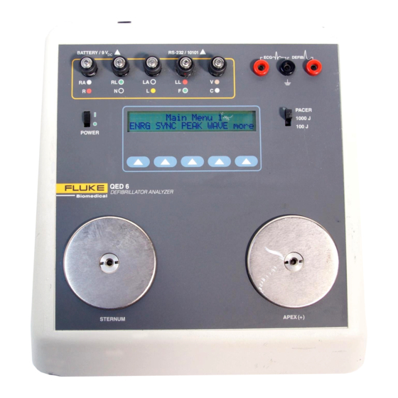
QED 6 Users Guide W Caution To avoid damage to the Analyzer or adverse affects on its performance, follow these guidelines: Do not expose the system to temperature extremes. Ambient temperatures should remain between 0 °C and 40 °C, with a relative humidity less than 90 %. System performance may be adversely affected if temperatures fluctuate above or below this range. - Page 19 Introduction and Specifications Instrument Familiarization BATTERY / 9VDC RS-232 / 10101 DEFIB PACER 1000 j 100 j SOFTKEYS STERNUM (-) APEX (+) fcf017.eps Figure 1-2. Analyzer Front Panel Layout...
-
Page 20: Front Panel
QED 6 Users Guide Front Panel The front panel of the Analyzer includes the elements described in Table 1-2. Table 1-2. Front Panel Elements Number Element Function Universal ECG Utilize AHA and International color coding, jacks allowing for waveform output to monitor/recorder. High Level Provides 1 volt peak output of the selected ECG Banana... -
Page 21: Back Panel
The Back Panel includes a battery holder that houses a 9-volt alkaline battery, and a dc battery eliminator jack. An RS232 D-9-pin serial port allows communications to a computer, serial printer, or other Fluke test equipment. Upgrading the Analyzer A number of pre-configured Analyzer models are available. In addition, older models may be upgraded by contacting the Fluke Biomedical Service Center. -
Page 22: Specifications
QED 6 Users Guide Specifications The following are specifications for the Analyzer. Please contact your Fluke Biomedical service representative for more information regarding the device specifications. General Display..............2-line x 24-character LCD supertwist alphanumeric Power ..............One 9 V Alkaline (Duracell MN1604 or equivalent);... -
Page 23: Specifications
Introduction and Specifications Specifications Synchronization Measurements Range ..............0-199.9 ms Measurement............From peak of R-wave From base of R-wave Accuracy ..............1 % of fullscale or ±2 ms ECG Waveforms QRS complex Rates ..............30, 60, 120, 180, 240 BPM Rate Accuracy ............ - Page 24 QED 6 Users Guide Defib Waveform Playback Time Base Expansion ..........100:1 @ 25 mm/sec paper speed; each division equals 40 ms Amplitude Scaling Lead II (RA-LL) 1000 J Range ..........1 mV = 3000 V 100 J Range ............1 mV = 900 V ECG Output 1000 J Range ............0.5 V = 3000 V 100 J Range ............0.5 V = 900 V...
- Page 25 Introduction and Specifications Specifications External Non-Invasive Pacer Measurements Load................ 50 ±1 %, non-inductive (< 10 µH) (Apex-Sternum) R-wave Amplitude........... 1.1 mV ±10 % (Apex-Sternum) 1 mV ±2 % Lead II (RA-LL) Pulse Width............. 1-50 ms Peak Vage .............. 0-12.5 V Peak Current............
-
Page 26: Accessories
QED 6 Users Guide Accessories The following are accessories for the Analyzer. To order, contact your Fluke Biomedical equipment dealer and use the Fluke Biomedical part numbers provided. Table 1-4 lists standard accessories shipped with the tester. Table 1-5 lists optional accessories that must be ordered separately. -
Page 27: Operation
Chapter 2 Operation Contents Page Introduction ................. 2-3 Powering Up ................2-4 Adjusting Display Contrast............2-9 Measuring Defibrillator Energy........... 2-9 Evaluating Ability to Fire ............2-12 Defibrillator Pulse Playback ............2-14 Viewing Oscilloscope Output............2-14 Preparation for Viewing ............2-14 Viewing a Test ................. - Page 28 QED 6 Users Guide...
-
Page 29: Introduction
Operation Introduction Introduction The Analyzer uses a 2-line x 24-character LCD display and softkeys to simplify operation. See Figure 2-1. Menu Choice Line Test Results Line BATTERY / 9VDC RS-232 / 10101 DEFIB PACER 1000 j 100 j SOFTKEYS STERNUM (-) APEX (+) fcf014.eps Figure 2-1. -
Page 30: Powering Up
QED 6 Users Guide The top line of the LCD display is used for test results and the bottom line provides menu choices. The five-position softkey pad is used to control the functions of the instrument. Make a menu selection by pressing the corresponding softkey. An audible beep verifies the selection. - Page 31 Operation Powering Up 3. Press esc in any submenu to return to the previous menu and, ultimately, to Main Menu 1. Figures 2-2 and 2-3 provide overviews of the menus and functions associated with Main Menu 1 and Main Menu 2, respectively. Figure 2-4 provides an overview of the Autosequence menu structure, accessed from the AUTO option of Main Menu 2.
- Page 32 QED 6 Users Guide fcf018.eps Figure 2-2. Main Menu 1 Functions...
- Page 33 Operation Powering Up fcf003.eps Figure 2-3. Main Menu 2 Functions...
- Page 34 QED 6 Users Guide fcf004.eps Figure 2-4. Autosequence Menu Structure (Main Menu 2)
-
Page 35: Adjusting Display Contrast
Operation Adjusting Display Contrast Adjusting Display Contrast Display contrast on the Analyzer may be adjusted to optimize viewing of menus and test data. To set the display contrast: 1. From Main Menu 2, press the UTIL softkey to display the following: fcf055.eps 2. -
Page 36: Available Waveforms
QED 6 Users Guide fcf006.eps 4. Press the WAV> softkey to browse through a list of available waveforms in Energy Mode. These waveforms are described in Table 2-1. Table 2-1. Available Waveforms Waveform Description ECG90 The default waveform; after a discharge, the ECG90 resumes. VFIB Ventricular Fibrillation VTACH... - Page 37 Operation Measuring Defibrillator Energy DEFIB PACER Defibrillator/Pacer fcf008.eps Figure 2-5. Defibrillator Energy Testing 6. Initiate a discharge from the defibrillator. 7. Observe the output settings and the actual readings displayed on the Analyzer and record them on the QEDR Performance Tag as shown in Figure 2-6.
-
Page 38: Evaluating Ability To Fire
QED 6 Users Guide Fluke Biomedicals fcf009.eps Figure 2-6. QEDR Performance Tag Note The Analyzer continues to display the reading until the next defibrillator pulse is fired. Evaluating Ability to Fire This test evaluates an automatic defibrillator for its ability to fire automatically after recognizing ventricular fibrillation and / or ventricular tachycardia. - Page 39 Operation Evaluating Ability to Fire DEFIB Defibrillator/Pacer PACER fcf010.eps Figure 2-7. ECG Lead Configuration 3. From the Energy menu, press the WAV> softkey until the VFIB option appears; then press the VFIB softkey. A ventricular fibrillation waveform is simulated by the Analyzer through the ECG jacks and paddle plates.
-
Page 40: Defibrillator Pulse Playback
QED 6 Users Guide Defibrillator Pulse Playback The Analyzer allows the user to play the defibrillator pulse waveform for the purpose of analysis. Playback is accomplished using a strip recorder or defibrillator monitor through the ECG jacks or scope output. The waveform can also be reviewed on an oscilloscope through the high-level ECG outputs. -
Page 41: Viewing A Test
Operation Viewing Oscilloscope Output 2. Make the following settings: Set the oscilloscope trigger on external and connect a lead between the input of the oscilloscope and the external trigger input. b. Set the time scale on the oscilloscope to 1 ms / division and adjust to the desired expansion after observing the waveform output. -
Page 42: Measuring Synchronization
QED 6 Users Guide Measuring Synchronization The Analyzer measures the synchronization time (cardioversion delay time) of synchronized defibrillators. A 90 BPM ECG waveform is output through the ECG jacks and the paddle plates. During normal operation, the defibrillator recognizes and responds to this trigger by discharging within a certain amount of time. - Page 43 Operation Measuring Synchronization Sync time measurements are performed as shown in Figure 2-8, below: QRS COMPLEX 90 BPM NSR Defib DEFIB PULSE Pulse Peak R-Wave Time Q-Wave Time fcf019.eps Figure 2-8. Sync Time Measurements 5. Set the range switch appropriately, as follows: Select the 1000 joule high range for defibrillator outputs over 100 joules or for an unknown defibrillator output power.
-
Page 44: Generating Test Waveforms
QED 6 Users Guide fcf020.eps Note The LCD displays the reading for about two seconds. Generating Test Waveforms The Analyzer generates a series of test waveforms designed to verify the accuracy of ECG machine / monitors. These waveforms, shown in Table 2-2 , are available for simulation via ECG jacks or paddle plates and are calibrated for lead II at 1 mV. - Page 45 Operation Generating Test Waveforms 3. Power up the Analyzer by sliding the power switch forward to ON. Main Menu 1 displays: fcf002.eps 4. Press the WAVE softkey to access the Waveform Type menu: fcf022.eps 5. Press the softkey corresponding to the desired wave simulation: ECG for ECG waveforms PERF for performance waveforms ARRH for arrhythmia waveform...
-
Page 46: Testing High Level Out
QED 6 Users Guide Testing High Level Out All waveforms available through the ECG jacks are simultaneously output through the High Level jacks. This scheme offers the user a 1-volt peak signal for testing purposes. To test a High Level signal, use an oscilloscope and a scope probe to measure the output waveform on the high level output. -
Page 47: Measuring Charge Time (Models M And H)
Operation Measuring Charge Time (Models M and H) 4. Set the range switch appropriately, as follows: Select the 1000 joule high range for defibrillator outputs over 100 joules or for an unknown defibrillator output power. Select the 100 joule low range for outputs under 100 joules. 5. -
Page 48: Pacemaker (Non-Invasive) Testing
QED 6 Users Guide 4. Press the two defibrillator paddles onto the contact electrode plates on the front of the Analyzer. 5. Press the START softkey and initiate the defibrillator charge cycle. 6. As soon as the defibrillator reaches full charge, discharge it, noting the time (in seconds) on the display. - Page 49 Operation Pacemaker (Non-Invasive) Testing ECG Leads BATTERY / 9VDC RS-232 / 10101 DEFIB PACER Pacer 1000 j 100 j SOFTKEYS Output STERNUM (-) APEX (+) Pacer Adapters fcf015.eps Figure 2-9. Connecting Pacemaker Output to Analyzer Note The Pacer can be in either demand or non-demand mode. 5.
-
Page 50: Pacemaker Refractory Period Testing
QED 6 Users Guide Note Pacer voltage and current are displayed as average voltage and current. If a printer is connected to the Analyzer, the printout also documents peak voltage and current. If computer control is being used, no peak values are available. All voltage measurements are referenced to the internal 50 load. - Page 51 Operation Pacemaker Refractory Period Testing fcf033.eps Three hyphens (---) indicate that no pacer pulses have been received. Definitions of the other abbreviations on the display are: PRP – Pulsed refractory period; the time (typically 20-500 ms) after a pulse is delivered from the pacemaker, during which the pacemaker does not detect cardiac activity.
-
Page 52: Programming An Automatic Test Sequence
QED 6 Users Guide Programming an Automatic Test Sequence The Model H can store in memory up to 28 automatic sequences to fully test defibrillator performance according to protocol. Standard defaults for Programs 0-27 for the Model H are listed in Table 2-3. Table 2-3. -
Page 53: Program Selection
Operation Programming an Automatic Test Sequence To program an automatic test sequence, carry out the following steps and those listed under individual headings, below: 1. From Main Menu 2, press the AUTO softkey to display the Autosequences menu: fcf034.eps 2. Press the PROG softkey to access the individual programs to be modified. fcf035.eps Program Selection 1. -
Page 54: Defib Setting
QED 6 Users Guide Defib Setting 1. Press STEP to advance to the next check item, Defib Setting. fcf037.eps 2. Press + or - to increase or decrease the defib setting. 3. Press NEXT for the next defib setting. Energy Limits 1. -
Page 55: Sync Time
Operation Programming an Automatic Test Sequence Sync Time 1. Press STEP to advance to the next check item, Sync-Time. fcf040.eps 2. Press the SEL softkey to toggle between Yes and No. Peak 1. Press STEP to advance to the next check item, Peak. fcf041.eps 2. -
Page 56: Ecg Performance
QED 6 Users Guide ECG Performance 1. Press STEP to advance to the next check item, ECG/Perf. fcf043.eps 2. Press + or - to advance to the next waveform. 3. Press SEL to program / deprogram a waveform. An * indicates that the item is programmed. -
Page 57: Running An Automatic Test Sequence
Operation Running an Automatic Test Sequence Note The changes are saved until the program is modified again, or the Analyzer is reset to factory defaults. Running an Automatic Test Sequence To run an automatic test sequence: 1. From Main Menu 2, press the AUTO softkey to display the Autosequences menu: fcf046.eps 2. -
Page 58: Printing The Analyzer Report Header
QED 6 Users Guide Printing the Analyzer Report Header All test reports created by the Analyzer can be printed via the RS232 port. To print the report header: 1. From Main Menu 1, press the ENRG softkey to access the Energy menu: fcf006.eps 2. - Page 59 Operation Printing the Analyzer Report Header Fluke Biomedical Control #: Serial #: Model #: Header Mfr. Location: Technician : Date: Setting Actual --------- 20.0 J Qwave Sync Time 43.9 ms Rwave Sync Time 73.1 ms Energy 19.9 J Over Voltage...
- Page 60 QED 6 Users Guide Fluke Biomedical Control #: Serial #: Model #: Mfr. Location: Technician: Date: PROGRAM NAME: PROG 5 Setting Actual Limit +/- 5% 10 J 10.3 J 100 J 10.3 J 200 J 199.0 J 300 J 300.0 J 360 J 360.0 J...
-
Page 61: Resetting The Analyzer To Factory Defaults
Operation Resetting the Analyzer to Factory Defaults PACER OUTPUT MEASUREMENTS Pulse Rate: 40 PPM Pulse Width: 0.0 ms Peak Current: 0.0 ma Peak Voltage: 0.0 V Ave Current 0.0 ma Ave Voltage: 0.0 V PACER REFRACTORY MEASUREMENTS Selected Pacing Rate: 40 PPM Pulsed Refractory Period: 329.2 ms... -
Page 62: Remote Operation
The Analyzer RS232 bi-directional interface allows communications with a PC, allowing the PC to send commands to the Analyzer. Such operation requires a Fluke RS232 cable and a bi-directional D-9 connector. The RS232 serial communications port originates from the microprocessor asynchronous serial port 0. -
Page 63: Serial Port Wiring Configuration
Unused Serial 232 Ground Use the Fluke serial cable to transfer data from the Analyzer serial port to any IBM (or compatible) computer or printer. The Data Terminal Equipment (DTE) wiring configuration is shown in Table 2-5. Table 2-5. Serial Cable Wiring Configuration... -
Page 64: Preparing For Serial Communications
QED 6 Users Guide Preparing for Serial Communications Several steps are required to prepare the Analyzer for serial communications with an attached computer. The first is setting parameters for RS232 data transfer. Note Ensure that the Baud Rate, Parity, Data, and Stop Bits settings selected for the Analyzer match those set on the computer. -
Page 65: Ansur Software Control
Performance tests Safety tests Ansur software utilizes plug-in modules to work with a wide array of Fluke Biomedical instruments. The plug-in module is a software interface to the Ansur program. Plug-ins provide test elements used by Ansur. This gives the benefit of using the same user interface for all testers and simulators supported by an Ansur plug-in. - Page 66 QED 6 Users Guide When you purchase a new Fluke Biomedical tester or simulator, you can update your existing Ansur software by installing a new plug-in. Each plug-in module lets you work only with the options and capabilities you need for the instrument you are testing.
-
Page 67: Maintenance, Service, And Calibration
Chapter 3 Maintenance, Service, and Calibration Contents Page Maintenance................. 3-3 Avoiding Damage ..............3-3 Cleaning ................... 3-3 Troubleshooting................3-4 Service and Calibration..............3-5... - Page 68 QED 6 Users Guide...
-
Page 69: Maintenance
Maintenance, Service, and Calibration Maintenance Maintenance The Analyzer requires little maintenance or special care; however, it is a calibrated measuring instrument and should be treated as such. The optional carry case is recommended for storage. It is further recommended that the storage environment be free from vibration. -
Page 70: Troubleshooting
QED 6 Users Guide Troubleshooting This section provides a brief troubleshooting guide to help you pinpoint potential problems with the Analyzer. Refer any additional problems to the Fluke Biomedical Service Center. Description Cause Action WARNING – LOW Low battery Replace battery... -
Page 71: Service And Calibration
If repairs or calibration are required, return the Analyzer to the factory or the nearest service center. 1. Before returning the Analyzer for factory service, contact Fluke Biomedical Service Center for a required Return Authorization Number. 2. Provide the following information:... - Page 72 Fluke Biomedical Service. 2. Enclose your return address and Return Authorization Number. 3. Insure the unit for full retail value and ship to the nearest Fluke Biomedical Service Center.
Need help?
Do you have a question about the QED 6 and is the answer not in the manual?
Questions and answers