
Subscribe to Our Youtube Channel
Related Manuals for Festool CMS OF GE


Summary of Contents for Festool CMS OF GE
-
Page 1: Router Table
CMS OF GE and VL Router Table Router Table Supplemental User’s Manual WARNING To reduce the risk of serious injury, read and understand all safety precautions and instructions in this manual before using this tool. -
Page 2: Limited Warranty
You are entitled to a free extended limited warranty (1 year ANY CONSEQUENTIAL, INCIDENTAL OR SPECIAL DAMAGES + 2 years = 3 Years) for your Festool power tool. Festool USA REGARDLESS OF THE THEORY OF LAW ON WHICH THE is responsible for all shipping costs during the first year of the CLAIM IS BASED. -
Page 3: Table Of Contents
Contents About This Manual ........... 3 Setup ............... 7 Tool Symbols ........... 3 Setting up the GE Base........7 General Power Tool Safety Warnings ....4 Setting up the VL Base........7 Work Area Safety .......... 4 Installing an OF 1010 Router ......8 Electrical Safety .......... -
Page 4: General Power Tool Safety Warnings
General Power Tool Safety Warnings WARNING! Read all safety warnings and Save all warnings and instructions instructions. Failure to follow the warnings and for future reference. instructions may result in electric shock, fire, and/ or serious injury. Refer to your router’s instruction manual for additional information. -
Page 5: Service
773 x 481 mm (30.4 x 18.9 in.) Intended Use The CMS Router Table is intended for use with either a Festool operating instructions. Using the tool in contravention to this OF 1010 or OF 1400 router. All applications beyond this are manual may lead to injury and will void your warranty. -
Page 6: Functional Description
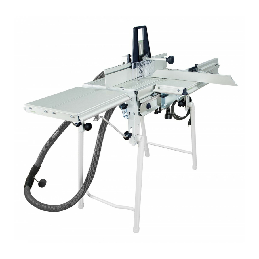
The Festool CMS-OF router table is available in two base configurations and with several optional accessories. The GE model is freestanding, and the VL model attaches to the edge of a Festool MFT/3 multi-function table. The basic package includes the legs, baseplate, fence, and curved guard. The optional accessories are sold separately. -
Page 7: Setup
Setup This section describes the basic setup of a new CMS OF Caution! Throughout this section, neither the router table system and the optional accessories that may router nor the router table should be connected to be added to the table. Operation-specific setup and configu- electrical power. -
Page 8: Installing An Of 1010 Router
Installing an OF 1010 Router 1. Place the router table baseplate upside down in the CMS 3. Place the OF 1010 centering ring in the opening of the base by engaging the hinge side and lowering the non- baseplate. hinged side. Part number 473810 is printed on the back. - Page 9 6. If the outrigger foot is installed on your router, remove 10. Install the 3 clamping dogs to the threaded standoff in it and replace it with the alignment tab. Make sure the the CMS baseplate. The flat, shorter leg goes against smaller of the tabs (4mm) is toward the base of the the router base.
- Page 10 13. Place the height adjustment crank on the top of the 23. Turn the 2 table latches clockwise to lock the baseplate leadscrew and lower the height adjustment tab until it in the base. almost touches the router. (It will be easier to invert 24.
-
Page 11: Installing An Of 1400 Router
26. Lock the router’s trigger in the On position by pulling the trigger and pressing the trigger lock. First release the trigger and then release the trigger lock. 27. Connect a vacuum hose to the dust port. Trigger 28. Connect the Plug-It cord to the Plug-It port on the Lock router. - Page 12 3. Place the OF 1400 centering ring in the opening of the 6. Invert the router onto the CMS table. baseplate. 7. Place the router over the centering ring with the 6mm Part number 473809 is printed on the back. This side alignment tab in the larger hole on the CMS baseplate.
- Page 13 10. Position the 3 clamping dogs on the router base and 16. Using the 2 finger holes, lift the front edge of the firmly tighten the thumbscrews. Make sure that the baseplate out of the base. dogs are not positioned over curved parts of the base 17.
- Page 14 24. The kit includes throat plates of various sizes that snap 26. Connect a vacuum hose to the dust port. into the router’s centering ring. Use the throat plate 27. Connect the Plug-It cord to the Plug-It port on the with the smallest opening that clears the router bit.
-
Page 15: Setting Up The Fence
Setting up the Fence The main fence is used for routing straight workpieces. 3. Install the featherboard assembly: It mounts to the table using the two thumbscrews shown a. Press the receiver release lever and tilt the feather- below. The thumbscrews are in slots that permit 50mm of board receiver to the vertical position. -
Page 16: Assembling The Optional Vacuum Splitter Hose
Assembling the Optional Vacuum Splitter Hose The optional vacuum splitter hose allows a single dust 6. Insert the two hoses into the Y-fitting. These are also extractor to be connected to both the fence’s dust port and left-hand threads, so turn the hoses counterclockwise. the router’s dust port. -
Page 17: Setting Up The Optional Extension Table
Setting up the Optional Extension Table The optional extension table is available only for the CMS Mounting GE model, and mounts to the outfeed end of the table. Slot 1. Loosen the adjustment screw on each mounting bracket, but not enough to remove it. 2. -
Page 18: Setting Up The Optional Sliding Table
Setting up the Optional Sliding Table The optional sliding table can be added to either the CMS 2. Place the sliding rail into the V-channel of the CMS table, GE or CMS VL tables. The only difference is that the GE and tighten the 2 thumbscrews into the nutplates (or base needs 2 nutplates added. - Page 19 The miter fence may be placed on the miter head in either 8. Loosen the angle lock knob and lift the index pin to the short profile or the tall profile positions. change the angle of the miter gauge. 7. Slide the miter fence over the clamping fingers in the The index pin can be disabled by lifting it and then ►...
-
Page 20: Operation
Operation Changing Router Bits Depending on the size of the router bit and your personal Changing Bits Below the Table preference, you can change router bits from above the The benefit of changing bits from under the table is that table, below the table, or by removing the table insert you can leave your fence in its existing position, but still and inverting it. -
Page 21: Freehand Routing With A Piloted Bit
Freehand Routing with a Piloted Bit A piloted router bit has a bearing above or below the cut- 7. Slide the start finger in or out until it is almost tangent ter that guides the cut based on the existing edge of the with the pilot bearing. -
Page 22: Fence Guided Profile Routing
Fence Guided Profile Routing Using the fence to guide the routing operation is the most 6. Raise the router to the desired height and remove the common application for the router table. This may be crank handle. performed with either a piloted or un-piloted router bit. Hint: For large router bits, you may want to take several shallow passes. -
Page 23: Cope And Stick (Stile And Rail) Routing
8. Install the featherboard assembly into the receiver and 11. If the workpiece is too wide for the horizontal feather- close the receiver to the down position. board, rotate the featherboard upward, slide it toward the fence, and then tighten the thumbscrew. 9. - Page 24 Note: Using the fence prevents the workpiece from 9. Install the stick cutter and set the height to match the being grabbed by the router bit before the workpiece position of your coped sample pieces. contacts the pilot bearing. 10. Set up the horizontal and vertical featherboards. 6.
-
Page 25: Offset Fence And Jointer Routing
Offset Fence and Jointer Routing The offset fence function is used when the router bit 7. Adjust the horizontal and vertical featherboards as removes the original reference edge that was guiding the appropriate. workpiece at the infeed to the router bit. The most common 8. - Page 26 Festool USA 400 N. Enterprise Blvd Lebanon, IN 46052 www.festoolusa.com Service Questions: 800-554-8741 Application Questions: 888-337-8600...
Need help?
Do you have a question about the CMS OF GE and is the answer not in the manual?
Questions and answers