EVGA P67 FTW User Manual
Hide thumbs
Also See for P67 FTW:
- Specifications (2 pages) ,
- Visual manual (2 pages) ,
- Information (2 pages)
Table of Contents
Advertisement
Quick Links
Advertisement
Table of Contents

Related Manuals for EVGA P67 FTW


Summary of Contents for EVGA P67 FTW
-
Page 1: User Guide
User Guide EVGA P67 FTW Motherboard... -
Page 3: Table Of Contents
User Guide ........................1 EVGA P67 FTW Motherboard..................1 Before You Begin… ...................... 6 Parts NOT in the Kit ....................7 Intentions of the Kit ....................7 EVGA P67 FTW Motherboard..................8 Motherboard Specifications..................8 Unpacking and Parts Descriptions ................10 Unpacking ...................... - Page 4 Post Port Debug LED and LED Status Indicators ..........32 Post Port Debug LED ..................32 LED Status Indicators ..................32 Installing Drivers and Software ..................33 Windows XP/Vista/7 Driver Installation ..............33 Appendix A. POST Codes...................34 EVGA Glossary of Terms ....................39 Compliance Information ....................42...
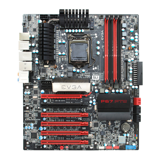
- Page 5 List of Figures Figure 1. EVGA P67 FTW Motherboard Layout ............ 15 Figure 2. Chassis Back Panel Connectors ............14 Figure 3. PW1 Motherboard Connector ..............21...
-
Page 6: Before You Begin
Before You Begin…... -
Page 7: Parts Not In The Kit
Parts NOT in the Kit Intentions of the Kit building replacing replacing... -
Page 8: Evga P67 Ftw Motherboard
EVGA P67 FTW Motherboard Motherboard Specifications... -
Page 10: Unpacking And Parts Descriptions
Unpacking and Parts Descriptions Unpacking Equipment... -
Page 12: Evga P67 Ftw Motherboard
EVGA P67 FTW Motherboard... - Page 14 Activity LED Status Description Speed/Link LED Status Description No data transmission Yellow 1000 Mbps data rate Blinking (Green) Data transmission Green 100 Mbps data rate 10 Mbps data rate Center/Subwoofer Side Speaker Out...
-
Page 15: Hardware Installation
Hardware Installation Safety Instructions... -
Page 16: Preparing The Motherboard
Preparing the Motherboard Installing the CPU down away Note: After removing the CPU socket cover, it is recommended that you keep it in case you need to remove the CPU so for any reason you can replace the cover to avoid damaging the CPU socket pins. -
Page 17: Installing The Cpu Fan
Note: Make sure the CPU is fully seated and level in the socket. Installing the CPU Fan... -
Page 18: Installing System Memory (Dimms)
Installing System Memory (DIMMs) -
Page 19: Installing The Motherboard
Installing the Motherboard Note: Be sure that the CPU fan assembly has enough clearance for the system case covers to lock into place and for the expansion cards. Also make sure the CPU Fan assembly is aligned with the vents on the covers. This will depend on the system case being used. -
Page 20: Securing The Motherboard Into The Chassis
Securing the Motherboard into a System Case Connecting Cables... -
Page 21: 24-Pin Atx Power (Pw1)
24-pin ATX Power (PW1) -
Page 22: 8-Pin Atx 12V Power (Pw12)
8-pin ATX 12V Power ( PW12-1 & PW12-2 +12V BIOS Select Switch Compact flash Connector... -
Page 23: Connecting Sata Cables
Connecting SATA Cables Connect the locking cable end to the motherboard connector. Connect the end without the lock to the SATA device. -
Page 24: Connecting Internal Headers
Connecting Internal Headers Front Panel Header Note: Some system cases do not have all four cables. Be sure to match the name on the connectors to the corresponding pins. -
Page 25: Ieee1394A (Firewire)
IEEE 1394a (Firewire) Card Edge... -
Page 26: Usb Headers
USB Headers... -
Page 27: Audio Header
Audio Card Edge... -
Page 28: Fan Connections
Fan Connections BIOS Ground +12V Sense Control Ground +12V Sense Control Ground +12V Sense Control Ground +12V Sense Control Ground +12V Sense Ground Control Ground +12V +12V Sense Sense Control Control... -
Page 29: Expansion Slots
Expansion Slots Note: When using 1 Graphics Card in PCI-E: Slot 2, a speed of x16 will be used. When using 2 or more Graphics Cards in PCI-E Slots: a speed of x8 will be used for all x16 or x8 slots. -
Page 30: Pci-E X1 Slots
PCI-E x1 Slots PCI-E x16/x8 Slots... -
Page 31: Onboard Buttons
Onboard Buttons Clear CMOS Button RESET and POWER Button... -
Page 32: Post Port Debug Led And Led Status Indicators
Post Port Debug LED and LED Status Indicators Post Port Debug LED LED Status Indicators... -
Page 33: Installing Drivers And Software
Installing Drivers and Software Note: It is important to remember that before installing the driver CD that is shipped in the kit, you need to load your operating system. The motherboard supports Windows XP , Vista and Windows 7 both 32 and 64 Bit. Windows XP/Vista/Win 7 Driver Installation... -
Page 34: Appendix A. Post Codes
Appendix A. POST Codes Power on. Reset type detection (soft/hard). AP initialization before microcode loading North Bridge initialization before microcode loading South Bridge initialization before microcode loading OEM initialization before microcode loading Microcode loading AP initialization after microcode loading North Bridge initialization after microcode loading South Bridge initialization after microcode loading OEM initialization after microcode loading Cache initialization... - Page 35 OEM pre-memory initialization codes Memory initialization. Serial Presence Detect (SPD) data reading Memory initialization. Memory presence detection Memory initialization. Programming memory timing information Memory initialization. Configuring memory Memory initialization (other). Reserved for ASL (see ASL Status Codes section below) Memory Installed CPU post-memory initialization is started CPU post-memory initialization.
- Page 36 is failed Internal CPU error reset PPI is not available Reserved for future AMI error codes S3 Resume is stared (S3 Resume PPI is called by the DXE IPL) S3 Boot Script execution Video repost OS S3 wake vector call Reserved for future AMI progress codes S3 Resume Failed Reserved for future AMI error codes...
- Page 37 South Bridge DXE SMM initialization is started South Bridge devices initialization South Bridge DXE Initialization (South Bridge module specific) ACPI module initialization CSM initialization 7A– Reserved for future AMI DXE codes 80– OEM DXE initialization codes Boot Device Selection (BDS) phase is started Driver connecting is started PCI Bus initialization is started PCI Bus Hot Plug Controller Initialization...
- Page 38 Ready To Boot event Legacy Boot event Exit Boot Services event Runtime Set Virtual Address MAP Begin Runtime Set Virtual Address MAP End Legacy Option ROM Initialization System Reset USB hot plug PCI bus hot plug Clean-up of NVRAM Configuration Reset (reset of NVRAM settings) Reserved for future AMI codes C0–...
-
Page 39: Evga Glossary Of Terms
EVGA Glossary of Terms... -
Page 42: Compliance Information
Original Purchaser. Upon termination, for any reason, all copies of Software and materials must be immediately returned to EVGA and the Original Purchaser shall be liable to EVGA.com CORP for any and all damages suffered as a result of the violation or default.
Need help?
Do you have a question about the P67 FTW and is the answer not in the manual?
Questions and answers