Table of Contents
Advertisement
M
Series
Model Number:
5900683
5900709
5900734
Description
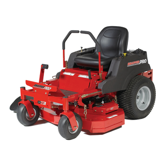
S50XKAV1936, 19HP Kawasaki, 36" Cut Zero-Turn Riding Mower
$50XBS2648, 26HP Briggs & Stratton, 48" Cut Zero-Turn Riding Mower
S50XKAV1948, 19HP Kawasaki, 48" Cut Zero-Turn Riding Mower
Briggs& Stratton Yard Power ProductsGroup
5375 North Main Street
Munnsville, NY 13409
800-933-6175
5101098
RevisionIR
Rev.Date:12/2007
TPlO0-7362-1R-M5-SP
Advertisement
Table of Contents
Troubleshooting

Related Manuals for Snapper S50XBS2648


Summary of Contents for Snapper S50XBS2648
- Page 1 Series Model Number: Description 5900683 S50XKAV1936, 19HP Kawasaki, 36" Cut Zero-Turn Riding Mower 5900709 $50XBS2648, 26HP Briggs & Stratton, 48" Cut Zero-Turn Riding Mower 5900734 S50XKAV1948, 19HP Kawasaki, 48" Cut Zero-Turn Riding Mower Briggs& Stratton Yard Power ProductsGroup 5101098 5375 North Main Street RevisionIR Munnsville, NY 13409 Rev.Date:12/2007...
- Page 2 Briggs & Stratton Yard Power Products Group Copyright © 2007 Briggs & Stratton Corporation Milwaukee, Wl, USA. All rights reserved. The Snapper Pro logo is a trademark of Briggs & Stratton Corporation Milwaukee, Wl, USA. Contact information: Briggs & Stratton Yard Power Products Group 5375 N.
-
Page 3: Table Of Contents
Tableof Contents Operator Safety ............. Safety Rules and Information ...........2 Safety Decals..............8 Safety interlock System............9 Features & Controls ..........Identification Numbers ...........10 Control Functions ............11 Operation ............General ................13 Checks Before Starting ...........13 Checking Tire Pressures..........14 Seat Adjustment .............14 Mowing Height Adjustment ..........15 Foot PedalAdjustment ............15 Starting the Engine............16 Stopping the Rider............16... -
Page 4: Operatorsafety
OperatorSafety OperatorSafety Safety Rules and Information OPERATING SAFETY Congratulations on purchasing a superior-quality piece of lawn and garden equipment. Our products are designed and manufactured to meet or exceed all industry standards for safety. Do not operatethis machine unless you have been trained. Readingand understanding this operator's manual is a way to train yourself. - Page 5 Operator Safety SLOPEOPERATION Operationon slopes can be dangerous. Using the unit on a slope that is too steep where you do not have adequatewheel traction (and control) can cause sliding, loss of steering, control, and possible rollover. You should not operate on a slope greater than a 5.4 foot rise over a 20 foot length (15 degrees).
- Page 6 OperatorSafety RETAiNiNGWALLS, DROP-OFFS, A NDWATER Retaining walls and drop-offs around steps and water are a common hazard. Giveyourself a minimum of two mower widths of clearancearound these hazards and hand-trim with a walk behind mower or string trimmer. Wheels dropping over retaining walls, edges, ditches, embankments, or into water can cause rollovers, which may result in serious injury, death, or drowning.
- Page 7 Operator Safety Readthese safety rules and follow them closely. Failureto obey these rules could result in loss of control of unit, severe personal injury or death to you, or bystanders, or damageto property or equipment. This mewing deck is capable of amputating hands and feet and throwinq objects. The triangle _ in text signifies important cautions or warnings which must be followed.
- Page 8 OperatorSalety Do Not spark arrester. It is a violation of California Public ResourceCode Section 4442 to use or operate the 1. Avoid starting, stopping, or turning on a slope, if tires engine on or near any forest-covered, brush-covered, or lose traction (i.e. machine stops forward motion on a grass-covered land unless the exhaust system is slope), disengage the blade(s) (PTO) and drive slow off equipped with a spark arrester meeting any applicable...
- Page 9 Operator Safety SERVICE AND MAINTENANCE Repair, if necessary,before restarting. 12. Park machine on level ground. Never allow untrained Toavoidpersonal i n_v or orooertv d amaoe,useextreme personnel to service machine. carein handlincLQasoline. Gasolineisextremelyflammable 13. Use jack stands to support components when required. andthevapors areexplosive.
-
Page 10: Safety Decals
,Operator S afety Safety Decals This unit has been designed and manufactured to provide you with the safety and reliability you would expect from an industry leader in outdoor power equipment manufacturing. Although reading this manual and the safety instructions it contains will provide you with the necessary basic knowledge to operate this equipment safely and effectively, we have placed several safety labels on the unit to remind... -
Page 11: Safety Interlocksystem
OperatorSafety Safety icons The alert symbol _ is used to identity safety information about hazards that can result in personal injury. A signal Safety interlockSystem word (DANGER,WARNING,or CAUTION)is used with the alert symbol to indicate the likelihood and the potential This unit is equipped with safety interlock switches. -
Page 12: Identification Numbers
FeaturessndControls Features and Controls identificationNumbers When contacting your authorizeddealer for replacement parts, service, or informationyou MUST have these numbers. Record your part number, serial number and engine serial numbers in the space provided on the inside front cover for easy access. These numbers can be found in the locations shown in Figure 1. -
Page 13: Control Functions
Features sndControls Figure 2. Control Locations ControlFunctions Theinformation below briefly describes the function of individual controls. Starting, stopping, driving, and mowing require the combined use of several controls appfied in specific sequences. Tolearn what combination and sequence of controls to use for various tasks see the OPERATION section. -
Page 14: Features & Controls
Features & Controls ParkingBrake Fuel TankCap To remove the cap, turn counterclockwise. DISENGAGE Releasesthe parking brake. Fuel Level Gauge ENGAGE Locks the parking brake. Displays the fuel level in the tank. Pull the parking brake lever up to engage the parking brake. Transmission Oil Fill Push the lever down to disengage the parking brake. -
Page 15: Operation
Operation Operation WARNING GeneralOperating Safety Before first time operation: Never operate on slopesgreater than (15°) which is a • Be sure to read all information in the Safety and rise of 5.4 feet (1,6 m) vertically in 20 feet (607 cm) Operation sections before attempting to operate this horizontally. -
Page 16: Checking Tire Pressures
Operatm CheckTire Pressures Tire pressure should be checked periodically, and maintained at the levels shown in the chart. Note that these pressures may differ slightly from the "Max Inflation" stamped on the side-wall of the tires. The pressures shown provide proper traction, improve cut quality, and extend tire life. -
Page 17: Mowing Heightadjustment
Operation Mowing HeightAdjustment The cutting height adjustment pin (A, Figure 6) controls the mower cutting height. The cutting height is adjustable between 1-1/2" (3,37 cm) and 4-1/2" (11,47 cm) in 1/4" (0,64 cm) increments. 1. Depressthe deck lift foot pedal (B) until it locks into the 4-1/2"... -
Page 18: Starting The Engine
OperaUon Pushing the Rider ByHand Starting the Engine NOTICE AWARNING DONOTTOW RIDER if you do not understandhow a specificcontrol Towingthe unitswill causetransmissiondamage. Do functions, or have not yet thoroughlyread the FEATURES & CONTROLS section, do so now. notuse another vehicle to pushor pull this unit. Do NOT attempt to operate the tractorwithout first becomingfamiliar with the locationand function of ALL controls. -
Page 19: Zero Turndriving Practice
Operation Smooth TraveJ Zero TurnDriving Practice The lever controls of the The lever controls of the Zero Turn rider are responsive, and Zero Turn rider are learning to gain a smooth and efficient control of the rider's responsive. forward, reverse, and turning movements will take some practice. - Page 20 OperaUon Practice TurningAround a Corner Practice Turningin Place To turn in place, "Zero Turn," gradually move one ground While traveling forward allow one lever to gradually return back toward neutral. Repeatseveral times. speed control lever forward from neutral and one lever back from neutral simultaneously.
-
Page 21: Mowing
Operation ,li i.i <, it,,/', Mowing ILl4 1. Engagethe parking brake. Make sure the PTOswitch is disengaged,the ground speed control levers are locked in the NEUTRALposition and the operator is on the seat. 2. Start the engine (see Starting The Engine). 3. -
Page 22: Mowingmethods
Operatm When and How Often to Mow The time of day and condition of the grass greatly affect the results you'll get when mowing. For the best results, follow these guidelines: 1. Mow when the grass is between three and five inches high. -
Page 23: Attaching A Trailer
Operation Proper Mulching Attaching A Trailer Mulching consists of a mower deck which cuts and recuts The maximum weight of a towed trailer should be less than clippings intotiny particles and which then blows them 200 Ibs (91kg). Secure the trailer with a appropriately sized down iNTO the lawn. -
Page 24: Regularmaintenance
RegWP MaJflteflaflce RegularMaintenance MaintenanceSchedule The following schedule should be followed for normal care of your rider and mower. You will need to keep a record of your operating time. Determining operating time is easily accomplished by observing the elapsedtime recorded by the hour meter. Safety items Before Every5... -
Page 25: Checking/Adding Fuel
RegWP MaJflteflaflce Checking / Adding Fuel WARNING To add fuel: Gasoline is highlyflammable and mustbe handled 1. Removethe fuel cap. with care. Never fill the tank when the engine is still 2. Fill the tank to about 1-1/2" (3,81 cm) of the bottom of hot from recent operation. -
Page 26: Lubrication
,ReguJap M aJflteflaflce Lubrication Lubricatethe unit at the locations shown in Figures 20 through 23 as well as the following lubrication points. Grease: • deck lift pivot blocks • mower deck spindles * front caster wheel axles & yokes • mower deck idler arm Use greasefittings when present. -
Page 27: Check Transmission Oil Level
RegularIVlaJntenance Check/ Fiil Transmission Oil Oil Type: 20W-50 conventional detergent motor oil. 1. Checkthe oil levelwhen the unit is cold. Locate the transmission oil reservoirs (A, Figure 24) located on the seat support plate. The oil should be up to the "FULL COLD"mark (B). -
Page 28: Servicing The Mower Blades
RegWP Maintenance Servicing The Mower Blades Removing the Mower Blade , CAUTION Avoid injury! Mower blades are sharp. * Always wear gloves when handlingmower blades or workingnear blades. 1. To remove the mower blade, use a 1" wrench on the flats of the spindle shaft and remove the mower blade mounting bolt with a 15/16"... - Page 29 RegWP MaJflteflaflce Sharpening the Mower 8Jade ACAUTION Avoid injury! Mower blades are sharp. • Alwayswear gloves when handlingthe mower blades. • Alwayswear safety eye protectionwhen grinding. ® 1. Sharpen the mower blades with grinder, hand file, or Figure 29. Sharpening the Mower Blade electric blade sharpener.
-
Page 30: Groundspeed Controlleveradjustment
RegWP MaJflteflaflce GroundSpeed ControlLeverAdjustment The control levers can be adjusted in three ways. The alignment of the control levers, the placement of the levers (how close the ends are to one another) and the height of the levers can be adjusted. To Adjust the Handle Alignment Loosen the mount bolts (A, Figure32) and pivot the lever(s) (B) to align with each other. -
Page 31: Parkingbrakeadjustment
.375" (0,95 cm). If not, position the set collar until the measurement equals .375" (0,95 cm). if this dues not currectthe brakingprobJem,see yuur Snapper Pru deaJer. Figure 34. Parking Brake Adjustment Brake Spring First Measurement - .50" (1,27 cm) -
Page 32: Return To Neutral Adjustment
RegularMaintenance Return-to-Neutral Adjustment To determine if it is necessary to adjust the neutral return, perform the following steps. © 1. Disengagethe PTO,engage the parking brake and turn off the engine. 2. Move the ground speed control levers into the operating position, pull the levers rearward and release. -
Page 33: Deck Rodtimingadjustment
RegWP MaJflteflaflce Deck RodTimingAdjustment 1. Park the machine on a fiat, level surface. Disengage the PTO,engage the parking brake, turn off the engine, and remove the ignition key. Rear tires must be inflated to 15 psi (1,03 bar); front tires to 40 psi (2,76 bar). 2. -
Page 34: Mower Belt Replacement
RegWP Maintenance Mower Belt Replacement- 36" DeckIVlodeis NOTICE To avoid damaging belts, DONOT PRY BELTSOVER PULLEYS. 1. Park the tractor on a smooth, level surface such as a concrete floor. Disengagethe PTO,engage the parking brake, turn off the engine, and remove the ignition key. 2. - Page 35 RegWP Maintenance 7. Install the new chevron belt on the right-hand sprocket and make sure that the belt is properly seated in the chevron of the sprocket. 8. Refer to Figure 42. Align the holes in the sprockets with the spindle mounting hardware as shown. The blades will be perpendicular to each other.
- Page 36 RegWP Maintenance Mower Belt Replacement- 48" DeckIVlodeis NOTICE To avoid damaging belts, DOHOT PRY BELTSOVER PULLEYS. 1. Park the tractor on a smooth, level surface such as a concrete floor. Disengagethe PTO,engage the parking brake, turn off the engine, and remove the ignition key. 2.
-
Page 37: Hydraulicpump Drive Belt Replacement
RegWP Maintenance HydraulicPump Drive Belt Replacement 5. Removethe old belt and replace it with the new one. Make sure the V-side of the belt runs in the grooves of 1. Park the tractor on a smooth, level surface such as a the crankshaft pulley and the transmission pulleys (B &... -
Page 38: Batterymaintenance
ReguJap M aJflteflaflce BatteryMaintenance NOTE: This unit is equipped with a maintenance-free BCIU1 battery. Cleaning the Battery and Cables A WARNING Be careful when handling the battery.Avoidspilling electrolyte. Keepflames and sparksaway from the battery. Whenremovingor installingbatterycables,disconnect the negativecable FIRSTand reconnect it LAST.if not donein thisorder, the positiveterminal canbe shortedto the frameby a tool. -
Page 39: Batteryservice
RegWP Maintenance Jump Starting With AuxiJiary (Booster)Battery BatteryService Jump starting is not recommended. However, if it must be Checking Battery Voltage done, follow these directions. Both booster and dis-charged AWARNiNG batteries should be treated carefully when using jumper cables. Follow the steps below EXACTLY, being careful not to cause sparks. - Page 40 RegWP MaJflteflaflce THIS HOOK-UP FOR NEGATIVE GROUND VEHICLES Starter Starter Switch Switch _ Jumper Cable Starting Discharged Vehicle Vehicle Battery Battery To Ground Engine Block MAKE CERTAIN VEHICLES DO NOT TOUCH Figure 48. Jump Starting WARNING ,A WARNING Any procedureother than the precedingcould result in: Foryour personalsafety, use extreme care when jump starting.
-
Page 41: Storage
RegularIVlaJflteflaflce Storage WARNING TemporaryStorage (30 DaysOr Less) Never storethe unit, with gasoline in engine or fueJ Remember,the fuel tank will still contain some gasoline, so tank, in a heated shelter or in enclosed, poorly ventilated enclosures. Gasoline fumes may reach an never store the unit indoors or in any other area where fuel open flame, spark or pilot light (such as a furnace, vapor could travel to any ignition source. -
Page 42: Troubleshooting
TeoubleshootJflg Troubleshooting Troubleshooting Chart AWARNING While normal care and regular maintenancewill extend the To avoid seriousinjury, perform maintenance on the life of your equipment, prolonged or constant use may tractor or mower only when the engine is stoppedand eventually require that service be performed to allow it to the parking brake engaged. -
Page 43: Troubleshooting The Mower
TPoubleshootiflg Rider Troub/eshooting Continued. Problem Cause Remedy Engineruns, but riderwill 1. Movethetransmissionreleaselever(s) to Transmission releaselever(s) not drive. the "closed"position• in "open" position• Belt is broken• See Drive Belt Replacement. Drive belt slips• See problem and cause below• Seeauthorized service dealer Brake is not fully released•... -
Page 44: Troubleshooting Commoncutting Problems
TroubleshootJflg Problems Troubleshooting CommonCutting Problem Cause Remedy 1. Sharpen your blades. Streaking. Blades are not sharp. Blades are worn down to far. 2. Replaceyour blades. Engine speed is too slow. 3. Always mow at full throttle. 4. Slow down. Ground speed istoo fast. 5. -
Page 45: Specifications
SpecificsUofls Specifications NOTE.Specifications are correct at time of printing and are subject to change without notice. ENGINE: TRANSMISSIONS: 19 HP Kawasaki idydroGearZL-KMEF-3LTC-1LLX(Lid) Make Kawasaki idydroGearZL-GMEF-3L7B-1LL×(Rid) Model FH580V Type ZT2800 Horsepower 19 @3600 rpm SAE 20W-50 motor oil Hydraulic Flnid Displacement 35.7 Cu. -
Page 46: Slope Identification Guide
,< 7" :iov-_n$ 7VOll_:IA v Hli_ _90_ SIH1 NgI7V www.SnapperPro.com... - Page 47 Ferris Industries - a division of Simplicity Manufacturing Inc. Owner's Limited Warranty Information (Effective 04/28/2004) Thank you for purchasing Ferris commercial mowing equipment. Please take a few minutes to read this limited warranty information. It contains all the information you will need to have your Ferris mower repaired in the unlikely event that a breakdown covered by this limited warranty should occur. Owner's Responsibilities - As a condition to our obligations under this limited warranty, you shall have read the operator's manual and you shall have...
- Page 48 MANUAL Series Zero-TurnRiding CommonService Parts: Product S pecifications: ENGINE: BELTS AND BLADES: TRACTOR 19 HP Kawasaki Pump Drive Belt 5022173 Make Kawasaki Model FH580V 36" MOWER DECK Oil Capacity 1.9 US qt. ( 1,8 L) w/Filter Timed Spindle Drive Belt 5049238 Deck Drive Belt 5101121...
Need help?
Do you have a question about the S50XBS2648 and is the answer not in the manual?
Questions and answers